Table of Contents
Advertisement
Quick Links
Download this manual
See also:
User Manual
Advertisement
Table of Contents

Related Manuals for Pro-face PS-3700A


Summary of Contents for Pro-face PS-3700A
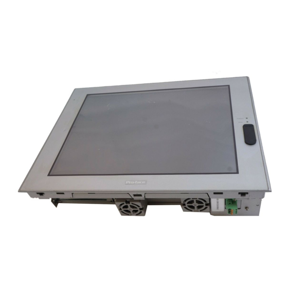
- Page 1 Compact Panel Computer PS-3700A (Eden ESP6000 - 667MHz Model) User Manual...
-
Page 2: Introduction
The PS-3700A (Eden ESP6000-667MHz Model) (PS-A) of Compact Panel Computers are multipurpose factory auto- mation (FA) computers, which embody Pro-face’s latest, cost-effective architecture. Before using the PS-A, read this manual thoroughly to familiarize yourself with the PS-A’s operation procedures and functions. -
Page 3: Essential Safety Precautions
Essential Safety Precautions This manual includes the following cautions concerning procedures that must be followed to operate the PS-A correctly and safely. Prior to operating the PS-A, be sure to read this manual and any related materials thoroughly to understand the correct operation and functions of this unit. - Page 4 After the PS-A’s backlight burns out, unlike the PS-A’s “Standby Mode”, the touch panel is still active. If the operator fails to notice that the backlight is burned out and touches the panel, a potentially dangerous machine operation error can occur. If your PS-A’s backlight suddenly turns OFF, use the following steps to determine if the backlight is actu- ally burned out.
- Page 5 HDD unit. In order to extend the lifetime of the hard disk, Pro-face recommends you set the Windows [Control panel]-[Power Management option]-[Turn off hard disks] selection to turn the hard disk off when the unit is not being operated.
-
Page 6: Information Symbols
Indicates pages containing related information. (1) (2) Indicates steps used to accomplish a given task. Be sure to follow these steps in the order they are written. Refers collectively to the Compact Panel Computers PS-3700A (Eden ESP6000- PS-A 667MHz Model) units. -
Page 7: Package Contents
Package Contents The following items are included in the PS-A’s package. Before using the PS-A, please confirm that all items listed here are present. PS-A (PS3700A-T41-ASU-E66) Moisture Resistant Gasket (1) Installation Fasteners (4/set x 2) USB Cable Clamp (1) AC Power Cord (1) AC Power Cord Clamp (1) CD-ROM (1) Installation Guide (1) -
Page 8: Ul/C-Ul (Csa) Application Notes
UL/c-UL (CSA) Application Notes PS3700A-T41-ASU-E66 unit is UL/c-UL listed product (UL File No. E220851). Please pay special attention to the fol- lowing instructions when applying for UL/c-UL approval for machinery which includes any of PS-A units. The PS-A conforms as a component to the following standards: UL508 Industrial Control Equipment CAN Std C22.2 No.14-1995 CAN/CSA 22.2 No.60950 PS3700A-T41-ASU-E66 (UL Registration Model No.:3280015-01) -
Page 9: Ce Marking Notes
CE Marking Notes PS3700A-T41-ASU-E66 unit is CE marked, EMC compliant product. <Complies with the following Standards> Safety EN60950 EN61000-6-4, EN55011(Group 1, Class A) EMS (EN61000-6-2/EN61131-2) EN61000-4-2, EN61000-4-3, EN61000-4-4, EN61000-4-5, EN61000-4-6, EN61000-4-8, EN61000-4-11, EN61000-4-12 47 CFR Part 15 Class A If the following requirements are not met, the PS-A may fail to meet EN60950 standard requirements. •... -
Page 10: Table Of Contents
Contents Introduction........................ 1 Essential Safety Precautions..................2 Information Symbols....................5 Package Contents ..................... 6 UL/c-UL (CSA) Application Notes ................7 CE Marking Notes ..................... 8 Contents ........................9 CHAPTER 1 Overview 1.1 Prior to Operating the PS-A Unit..............1-2 1.2 PS-A Unit System Configuration..............1-3 1.2.1 Setting Up the Touch Panel Connection ...............1-4 1.2.2 Using the USB Interface (located on the front face) ..........1-4 1.3 PS-A Unit Part Names and Features .............. - Page 11 2.3 Wiring the PS-A .................... 2-16 2.3.1 Connecting the Power Cord................2-16 2.3.2 Power Supply Cautions..................2-17 2.3.3 Grounding Cautions ....................2-19 2.3.4 Cautions When Connecting I/O Signal Lines............2-19 CHAPTER 3 System Setup 3.1 Setup Procedures ................... 3-2 3.2 System Parameters ..................3-3 3.2.1 Standard CMOS Features..................3-3 3.2.2 IDE HDD Auto-Detection ..................3-5 3.2.3 Advanced BIOS Features ..................3-6...
- Page 12 CHAPTER 5 Monitoring Features 5.1 RAS Features ....................5-2 5.1.1 PS-A RAS Features ....................5-2 5.1.2 RAS Feature Details .....................5-3 5.1.3 RAS Feature Overview ..................5-5 5.2 System Monitor/RAS Features ............... 5-6 5.2.1 Setup Procedures ....................5-6 5.2.2 System Monitoring Property Settings (PSA_Wps.exe) .........5-7 5.2.3 System Monitoring Operation (PSA_Smon.exe)...........5-9 5.2.4 Error Messages ....................5-12 5.3 Error Displays When Using Event Viewer.............
- Page 13 Appendices A.1 Hardware Configuration................App-2 A.1.1 I/O Map......................App-2 A.1.2 Memory Map....................App-3 A.1.3 Interrupt Map ....................App-4 A.2 List of Optional Devices ................App-5 Index...
-
Page 14: Prior To Operating The Ps-A Unit
Overview 1. Prior to Operating the PS-A Unit 2. PS-A Unit System Configuration 3. PS-A Unit Part Names and Features 4. Interfaces 5. PS-A Unit External Views and Dimensions... - Page 15 Compact Panel Computer PS-3700A (Eden ESP6000-667MHz Model) User Manual 1.1 Prior to Operating the PS-A Unit The following explanation shows the preparation steps required prior to operating the PS-A. Connect the display unit and any optional devices. Connect Peripheral Devices 1.2 PS-A Unit System Configuration...
- Page 16 Chapter 1 Overview 1.2 PS-A Unit System Configuration The following chart shows the range of peripheral items connected to the PS-A. PS3700A-T41-ASU-E66 *1*2 HDD Unit IDE Connector Main Memory *1*2 Main Memory Module Connector Peripherals COM1/COM2/COM3/COM4 (commercial type) RS-232C Cable Printer Connector Printer Cable (commercial type)
-
Page 17: Setting Up The Touch Panel Connection
Compact Panel Computer PS-3700A (Eden ESP6000-667MHz Model) User Manual 1.2.1 Setting Up the Touch Panel Connection The connection method used can be via either a serial (RS-232C) or USB interface. Depending on the type of Touch Panel connection used, the OS types that can be used will vary. -
Page 18: Ps-A Unit Part Names And Features
Chapter 1 Overview 1.3 PS-A Unit Part Names and Features 1 : Display / Touch Panel 2 : Power Lamp LED (POWER) PS-A Status Normal Operation Green (Power On) System Monitor Error Orange Touch Panel Self Test Error Orange/Red Backlight is not functioning : IDE Access Lamp Front PS-A Status... - Page 19 Compact Panel Computer PS-3700A (Eden ESP6000-667MHz Model) User Manual 24 : Speaker Output Connector (SPEAKER OUT) 25 : Mike Input Connector (MIC IN) 26 : Printer Connector (LPT1) 27 : Cooling FAN 28 : CF Card Slot 29 : AC Inlet Connector •...
-
Page 20: Interfaces
Chapter 1 Overview 1.4 Interfaces 1.4.1 RS-232C Interface (COM1/COM2/COM3/COM4) RS-232C Interface (COM1/COM2/COM3/COM4) Pin Arrangement PIN# Signal Condition Direction Carrier Detect Input Receive Data Input Send Data Output Data Terminal Ready Output Signal Ground Data Set Ready Input Request Send Output Clear Send Input RI / 5V... - Page 21 Compact Panel Computer PS-3700A (Eden ESP6000-667MHz Model) User Manual Switches The following switch settings corresponding to each Serial Interface need to be signified. To set the switches, remove the PS-A’s Rear Cover and locate the following switches, next to the PS-A’s circuit board. For infor- mation about attaching/removing the Rear Cover, 2.1.1 Removing the PS-A Unit's Cover (page2-2)
- Page 22 Chapter 1 Overview DIPSW2 Description RS-422 RS-485 232C Changes COM1 +5V 500mA (RS-232C) #9 pin external output (RI <-> +5V) possible Changes COM3's RS-422/RS-485 RS-232C communication method Changes COM2 +5V 500mA (RS-232C) #9 pin external output (RI <-> +5V) possible TX data output is TX data output is Changes TX data's...
-
Page 23: Printer Interface (Lpt1)
Compact Panel Computer PS-3700A (Eden ESP6000-667MHz Model) User Manual 1.4.2 Printer Interface (LPT1) This interface conforms to Centronics standards. D-sub 25 pin (Female) • Electrical Specifications O.D : Open Drain : 3 state I/O TTL : TTL Input Screw Size: (4-40): Inch Type... -
Page 24: Ps-A Unit External Views And Dimensions
Chapter 1 Overview 1.5 PS-A Unit External Views and Dimensions 1.5.1 PS-A Unit Unit:mm [in] 383 [15.08] 100 [3.94] 395 [15.55] 5 [0.20] Front Side 1-11... -
Page 25: External Dimensions (With Installation Fasteners Installed)
Compact Panel Computer PS-3700A (Eden ESP6000-667MHz Model) User Manual 1.5.2 External Dimensions (with Installation Fasteners installed) Unit:mm [in] 394.8 [15.54] 160[6.30] 160[6.30] 100 [3.94] 404.8 [15.94] 5 [0.20] Side Front Side Rear Bottom [6.30] [6.50] 1-12... -
Page 26: Panel Cut Dimensions
Chapter 1 Overview 1.5.3 Panel Cut Dimensions Unit:mm [in] +0.04 383.5 [15.10 • Be sure the thickness of the installation panel is from 1.6 mm [0.06 in] to 10 mm [0.39 in]. • All panel surfaces used should be strengthened. Especially, if high levels of vibra- tion are expected and the PS-A’s installation surface (i.e. - Page 27 Compact Panel Computer PS-3700A (Eden ESP6000-667MHz Model) User Manual Memo 1-14...
-
Page 28: Installtion
Hardware Installation 1. Installtion 2. Installing the PS-A Unit 3. Wiring the PS-A... -
Page 29: Removing The Ps-A Unit's Cover
Compact Panel Computer PS-3700A (Eden ESP6000-667MHz Model) User Manual 2.1 Installtion A wide variety of optional units, Main Memory, CF cards, PCMCIA (PC cards) manufactured by Digital Electronics Corporation and commercial expansion boards (PCI bus compatible board *1), PCMCIA (PC Cards) can be used with the PS-A. -
Page 30: Ps-A Internal View
Chapter 2 Hardware Installation 2.1.2 PS-A Internal View Expansion Board Interface (1 port) HDD Unit CD-ROM Drive FDD Drive PCMCIA Slot (2 ports) Main Memory Installation Area (1 port) -
Page 31: Main Memory Installation
Compact Panel Computer PS-3700A (Eden ESP6000-667MHz Model) User Manual 2.1.3 Main Memory Installation (1) Remove the PS-A unit's rear cover. 2.1.1 Removing the PS-A Unit's Cover (page2-2) (2) Angle the main memory module down slightly, and push it in until the connector pins mate with the module's pins. - Page 32 Chapter 2 Hardware Installation (3) Insert the expansion board (commercial-type PCI) into the expansion board connector, and secure it in place using the filler panel’s screw. The necessary torque is 0.5N•m to 0.6N•m. Expansion Board Connector Expansion Board (Commercial type) (4) Replace the rear cover and secure it in place using the five (5) attachment screws.
-
Page 33: Pcmcia Unit Installation
(3) Replace the PCMCIA slot cover removed in (1) and secure it in place using the two PCMCIA slot screws. The necessary torque is 0.5N•m to 0.6N•m. • When using a PC Card with a cable attached, Pro-face recommends you use a clamp or other type of device to prevent vibration from possibly dislodging the cable. -
Page 34: Usb Cable Clamp Installation
Chapter 2 Hardware Installation 2.1.6 USB Cable Clamp Installation This holder prevents the USB cable from becoming disconnected due to vibration, etc. (1) Place the PS-A unit face-down on a flat surface as shown below. Your PS-A unit has two USB connec- tors. -
Page 35: Cf Card Installation And Removal
Compact Panel Computer PS-3700A (Eden ESP6000-667MHz Model) User Manual 2.1.7 CF Card Installation and Removal When using the PS-A Unit and a CF Card, follow the precautions below: Be sure to use only CF Cards manufactured by the Digital Electronics Corporation. PS-A unit performance cannot be guaranteed when using another manufacturer's CF Card. - Page 36 Chapter 2 Hardware Installation When inserting the CF Card (1) Unscrew the CF Card cover's attachment screw (1), and remove the CF Card cover. CF Card Cover (2) Insert the CF Card firmly into the CF card slot, and check that the eject button pops out. CF Card Eject Button Removing the CF Card...
-
Page 37: Installing The Ps-A Unit
Compact Panel Computer PS-3700A (Eden ESP6000-667MHz Model) User Manual 2.2 Installing the PS-A Unit 2.2.1 Installation Caution Temperature Related Cautions • The PS-A should be installed in a vertical position, and forced air cooling should be used, instead of natu- ral air circulation. - Page 38 Chapter 2 Hardware Installation Installation Location • Avoid placing the PS-A next to other devices that might cause overheating. • Keep the PS-A away from arc-generating devices such as magnetic switches and non-fuse breakers. • Avoid using the PS-A in environments where corrosive gases are present. •...
-
Page 39: Installation Procedures
Compact Panel Computer PS-3700A (Eden ESP6000-667MHz Model) User Manual 2.2.2 Installation Procedures Follow the steps given below when installing the PS-A. Attaching the Installation Gasket Even if the your PS-A’s Installation Gasket is not needed to prevent water from entering the unit, the gasket also acts as a vibration absorber and should always be attached. - Page 40 Chapter 2 Hardware Installation Create a Panel Cut Create a panel cut for the PS-A, like that pictured here. Two additional items, the installation gasket and the installation fasteners are required when installing the PS-A. 1.5.3 Panel Cut Dimensions (page1-13) Panel Panel Cut •...
- Page 41 Compact Panel Computer PS-3700A (Eden ESP6000-667MHz Model) User Manual Insert the PS-A into the installation slot Unit:mm [in] Mounting panel 383.5 +0.04 [15.10 Side panel PS-A • Be sure the panel cut’s actual measurements are the same as those given here, otherwise the PS-A may slip or fall out of the panel.
- Page 42 Chapter 2 Hardware Installation Attach and Secure the Rear Installation Fasteners (1) Locate the PS-A’s attachment holes, located on the top, bottom, and sides of the PS-A. Bottom Attachment Holes Right Side Left Side Panel Installation Fastener PS-A • Excessive torque may damage the PS-A unit. •...
-
Page 43: Wiring The Ps-A
Compact Panel Computer PS-3700A (Eden ESP6000-667MHz Model) User Manual 2.3 Wiring the PS-A 2.3.1 Connecting the Power Cord Insert the power cord (AC inlet plug) into the PS-A's bottom face AC connector. To avoid an electric shock, check that the PS-A's power supply is turned OFF, via a breaker, or similar unit before connecting the PS-A's power cord to the AC connector. -
Page 44: Power Supply Cautions
Chapter 2 Hardware Installation (2) Connect the AC plug to the PS-A’s AC connector, as shown in fig. 2. Lock Pin Hole Cord Clamp Lock Pin Lock Tab Release AC Connector AC Plug AC Plug Collar Cord Clamp Figure 2 (3) Insert the Cord Clamp Lock Pin into the PS-A’s Lock Pin Hole. - Page 45 Compact Panel Computer PS-3700A (Eden ESP6000-667MHz Model) User Manual • Wire the power cords of the PS-A, I/O AC100V devices, and power supply devices sepa- PS-A PS-A Main power rately. power source source device power source • To improve noise immunity, it is recom-...
-
Page 46: Grounding Cautions
Chapter 2 Hardware Installation 2.3.3 Grounding Cautions (a) Dedicated Ground *1 • Set up a dedicated ground when using the rear panel’s FG terminal. PS-A Other device (b) Shared Ground - allowed *1 • If a dedicated ground is not possible, use a shared ground, as shown in figure. - Page 47 Compact Panel Computer PS-3700A (Eden ESP6000-667MHz Model) User Manual Memo 2-20...
-
Page 48: Chapter 3 System Setup
System Setup 1. Setup Procedures 2. System Parameters... - Page 49 Compact Panel Computer PS-3700A (Eden ESP6000-667MHz Model) User Manual 3.1 Setup Procedures • Normally, use only the factory (default) settings. • The following settings are those pre-set at the factory. (1) Connect a keyboard to the PS-A. (2) Turn the PS-A’s power ON.
-
Page 50: System Parameters
Chapter 3 System Setup 3.2 System Parameters 3.2.1 Standard CMOS Features • Normally, use only the factory (default) settings. Selecting the STANDARD CMOS FEATURES menu item produces the following screen. Phoenix AwardBIOS CMOS Setup Utility Standard CMOS Features Item Help Date (mm:dd:yy): Wed,Jun 25 2003 Time (hh:mm:ss):... - Page 51 Compact Panel Computer PS-3700A (Eden ESP6000-667MHz Model) User Manual IDE Primary (Secondary) Master (Slave) Displays the name of the IDE type Hard Disk connected to the PS-A. Pressing the [Enter] key will call up the Parameter settings menu. For details, 3.2.2 IDE HDD Auto-Detection (page3-5)
-
Page 52: Ide Hdd Auto-Detection
Chapter 3 System Setup 3.2.2 IDE HDD Auto-Detection Selecting either [IDE Primary (Secondary) Master] or [IDE Primary (Secondary) Slave] will call up the fol- lowing menu. The following example uses the [IDE Primary Master] setting. Phoenix AwardBIOS CMOS Setup Utility IDE Primary Master IDE HDD Auto-Detection [Press Enter]... -
Page 53: Advanced Bios Features
Compact Panel Computer PS-3700A (Eden ESP6000-667MHz Model) User Manual 3.2.3 Advanced BIOS Features Selecting the ADVANCED BIOS FEATURES menu item calls up the following screen. Phoenix AwardBIOS CMOS Setup Utility Advanced BIOS Features Item Help Virus Warning [Disabled] CPU Internal Cache... -
Page 54: Quick Power On Self Test
Chapter 3 System Setup Quick Power On Self Test This setting determines whether the quick self test is performed when the power is turned on. The available settings are [Disabled] or [Enabled]. The factory default setting is [Enabled] and is recommended for most users. -
Page 55: Security Option
Compact Panel Computer PS-3700A (Eden ESP6000-667MHz Model) User Manual Typematic Delay (Msec) When [Typematic Rate Setting] is set to [Enabled], this setting determines the delay period until the initial repetition is started. The [250] selection is factory set and is recommended for most users. -
Page 56: Advanced Chipset Features
Chapter 3 System Setup 3.2.4 Advanced Chipset Features Selecting the ADVANCED CHIPSET FEATURES menu item calls up the following screen. Phoenix AwardBIOS CMOS Setup Utility Advanced Chipest Features DRAM Timing by SPD [Enabled] Item Help Memory Hole [Disabled] P2C/C2P Concurrency [Enabled] Menu Level System BIOS Cacheable... - Page 57 Compact Panel Computer PS-3700A (Eden ESP6000-667MHz Model) User Manual Video BIOS Cacheable Sets whether the Video BIOS Cache is used or not. Settings available are [Enabled] and [Disabled]. The fac- tory setting is [Disabled]. When this feature is [Enabled], the BIOS ROM range available for caching is from C0000h - F7FFFh, which will improve video performance.
-
Page 58: Pci Delay Transaction
Chapter 3 System Setup PCI Master O WS Write Designates the wait time used when writing data to the PCI board. Available selections are [Enabled] and [Disabled]. Selecting [Enabled] means there is no wait time. The factory setting is [Enabled]. PCI Delay Transaction Controls the transaction delay function. -
Page 59: Integrated Peripherals
Compact Panel Computer PS-3700A (Eden ESP6000-667MHz Model) User Manual 3.2.5 Integrated Peripherals Selecting INTEGRATED PERIPHERALS SETUP menu item Displays the following screen. Phoenix AwardBIOS CMOS Setup Utility Integrated Peripherals OnChip IDE Channel 0 [Enabled] Item Help OnChip IDE Channel 1... -
Page 60: Init Display First
Chapter 3 System Setup Primary (Secondary) Master (Slave) PIO Designates the IDE Primary (Secondary) Master (Slave) channel’s PIO data transfer mode. Available selections are [Auto], [Mode 0], [Mode 1], [Mode 2], [Mode 3] and [Mode 4]. The factory setting is [Auto]. IDE Primary (Secondary) Master (Slave) UDMA Designates the IDE Primary (Secondary) Master (Slave) channel’s UDMA data transfer mode. -
Page 61: Onboard Parallel Port
Compact Panel Computer PS-3700A (Eden ESP6000-667MHz Model) User Manual Onboard Serial Port 2 Designates the PS-A’s Serial Port2 I/O address and interrupts. The selections include [Disabled], [Auto], [3F8/ IRQ4], [2F8/IRQ3], [3E8/IRQ4] and [2E8/IRQ3]. The [2F8/IRQ3] selection is factory set and recommended for most users. - Page 62 Chapter 3 System Setup ECP Mode Use DMA Designates the ECP mode's DMA channel. [1] and [3] are available selections, however, this item can be set when the Parallel Port Mode is set to [ECP], [ECP+EPP 1.7]or [ECP+EPP 1.9]. The factory default setting is [3].
-
Page 63: Power Management Setup
Compact Panel Computer PS-3700A (Eden ESP6000-667MHz Model) User Manual 3.2.6 Power Management Setup Selecting the POWER MANAGEMENT SETUP menu item calls up the following screen. Phoenix AwardBIOS CMOS Setup Utility Power Management Setup ACPI Function [Enabled] Item Help Power Management... -
Page 64: Video Off Method
Chapter 3 System Setup Video Off Method This setting determines the method to blank the display screen. The available settings are [Blank Screen], [V/ H SYNC+Blank], and [DPMS]. The [Blank Screen] selection blanks the display. The [V/H SYNC+Blank] blanks the display and also suspends the Vertical/Horizontal synchronization signal of the display. The [DPMS] selection controls the operation when a CRT that supports DPMS* is used. -
Page 65: Pnp/Pci Configurations
Compact Panel Computer PS-3700A (Eden ESP6000-667MHz Model) User Manual 3.2.7 PnP/PCI Configurations Selecting the PnP/PCI Configuration menu item Displays the following screen. Phoenix AwardBIOS CMOS Setup Utility PnP/PCI Configurations PNP OS Installed [No] Item Help Reset Configuration Data [Disabled] Menu Level... -
Page 66: Irq Resources
Chapter 3 System Setup PCI/VGA Palette Snoop The two selections available are [Disabled] and [Enabled]. The [Disabled] selection is factory set and recom- mended for most users. However, if a VGA or MPEG board is used, set this to [Enabled]. For setting details, refer to your VGA or MPEG board’s Installation guide. -
Page 67: System Monitor Setup
Compact Panel Computer PS-3700A (Eden ESP6000-667MHz Model) User Manual 3.2.9 System Monitor Setup Select PC Health Status from the System Monitor Setup and the following screen will appear. Phoenix AwardBIOS CMOS Setup Utility System Monitor Setup Warning Voltage +3.3V [Disabled]... -
Page 68: Frequency/Voltage Control
Chapter 3 System Setup System Fan Speed Limit If the system fan’s RPM level falls below the set value, this feature, as part of system monitoring, issues a warning. The available settings are [Enabled] and [Disabled]. The factory default setting is [Disabled]. Power Fan Speed Limit When enabled, this setting designates the allowed speed range reductions allowed for Power FAN. -
Page 69: Load Optimized Defaults
Compact Panel Computer PS-3700A (Eden ESP6000-667MHz Model) User Manual 3.2.12 Load Optimized Defaults Selecting [Load Optimized Defaults] designates whether or not you will revert to the PS-A unit’s factory set- tings. The selections are [Y] and [N]. • When the PS-A unit uses its factory settings, the USB interface cannot be used. -
Page 70: Set Supervisor Password
Chapter 3 System Setup 3.2.13 Set Supervisor Password This password is used to change system information settings. It is designed to prevent unapproved users from changing the system information settings. Entering up to 8 characters here will overwrite the current pass- word. - Page 71 Compact Panel Computer PS-3700A (Eden ESP6000-667MHz Model) User Manual Memo 3-24...
-
Page 72: Cd-Rom Contents
Setting up Your PS-A Unit 1. CD-ROM Contents 2. Setting Up Your PS-A Unit 3. Installing Drivers 4. Special Application Program Features 5. When Using Windows®2000/Windows®XP... -
Page 73: Software
Compact Panel Computer PS-3700A (Eden ESP6000-667MHz Model) User Manual 4.1 CD-ROM Contents 4.1.1 Software This section explains the organization of the software included in the accessory CD-ROM. PS370XA-E66 User Manual & Driver CD [Driver] [4 in 1] 4 in 1 Driver <Supported OS types>... -
Page 74: Setting Up Your Ps-A Unit
Chapter 4 Setting up Your PS-A Unit 4.2 Setting Up Your PS-A Unit There are two types of PS-A units. One has a hard disk with no pre-installed OS and one has a hard disk with a pre-installed OS. Therefore, the setup procedures used will differ. This manual describes only the proce- dures for setting up a PS-A unit using a hard disk with no pre-installed OS. - Page 75 Compact Panel Computer PS-3700A (Eden ESP6000-667MHz Model) User Manual Installing Software from the PS370XA-E66 User Manual & Driver CD-ROM To begin the installation, click on the “Setup.exe” file in your OS’ folder. ® Example) With Windows D:\Utility\WinXP\Disk1\Setup.exe (When the CD-ROM drive is “D”) ®...
-
Page 76: Setting Up An Hdd With Pre-Installed Os
Chapter 4 Setting up Your PS-A Unit Installing the HDD Unit After opening the PS-A unit’s packing box, check that a hard disk unit is installed. If it is not, you will need to install it. Pre-installed HDD Unit Installation Guide Setting Up the PS-A Unit’s System Information If your PS-A unit does not have a pre-installed HDD, you will need to install an HDD unit and then configure that drive’s system information. -
Page 77: Installing Drivers
Compact Panel Computer PS-3700A (Eden ESP6000-667MHz Model) User Manual 4.3 Installing Drivers Four types of dedicated PS-A drivers (4 in 1, Audio, graphic accelerator, and USB 1.1) are available. Install the required drivers from this data when using a PS-A with no pre-installed OS (A PS-A unit that has been recovered using the Recovery CD-ROM will have all the required drivers installed). -
Page 78: Special Application Program Features
Chapter 4 Setting up Your PS-A Unit 4.4 Special Application Program Features The special programs designed for the PS-A unit are located in the following folders. ® ® File Name Windows Windows 2000 PSA_RAS.DLL PSA_DLL.DLL PSA_IOC.DLL C:\Windows\System32 C:\Winnt\System32 PSA_BLC.DLL Backlight Control.scr Bl Bright.cpl Disp.exe C:\Proface\Disp... - Page 79 Compact Panel Computer PS-3700A (Eden ESP6000-667MHz Model) User Manual System Monitoring/RAS Applications: PSA_Smon.exe/PSA_Wps.exe The RAS and System Monitoring features allow users to monitor temperature voltage, and fan operation ® alarms. This program runs on Windows System Monitoring Program: PSA_Smon.exe 5.2.3 System Monitoring Operation (PSA_Smon.exe) (page5-9) Watchdog Parameter Setup Program: PSA_Wps.exe...
-
Page 80: Uninstalling Utility Software
Chapter 4 Setting up Your PS-A Unit Backlight Brightness Adjustment (Bl Bright.cpl) Backlight brightness can be set to one of four levels: Level 0, Level 1, Level 2 or Level 3. Brightness level 0: Very dark Brightness level 1: Somewhat dark Brightness level 2: Somewhat bright Brightness level 3: Very bright To use this program, click the [Control Panel]’s [Backlight Brightness] icon. -
Page 81: When Using Windows®2000/Windows®Xp
Compact Panel Computer PS-3700A (Eden ESP6000-667MHz Model) User Manual ® ® 4.5 When Using Windows 2000/Windows 4.5.1 Automatic System Log-on Setup This setting allows users to simplify password entry at startup. ® Windows 2000 (1) Double-click on the [Control Panel]’s [User and Password] icon. -
Page 82: Uninterrupted Power Supply System (Ups)
Chapter 4 Setting up Your PS-A Unit 4.5.2 Uninterrupted Power Supply System (UPS) Be sure to shut down your OS before turning off your machine. Also, use of an uninterrupted power supply is recommended to protect your data from accidental power failures. An uninterrupted power supply will give you sufficient time to shut down your system safely in case of a ®... - Page 83 Compact Panel Computer PS-3700A (Eden ESP6000-667MHz Model) User Manual Memo 4-12...
-
Page 84: Ras Features
Monitoring Features 1. RAS Features 2. System Monitor/RAS Features 3. Error Displays When Using Event Viewer 4. Remote RAS 5. Remote Shutdown Feature... -
Page 85: Ps-A Ras Features
Compact Panel Computer PS-3700A (Eden ESP6000-667MHz Model) User Manual 5.1 RAS Features 5.1.1 PS-A RAS Features RAS (Reliability, Availability, Serviceability) features include a variety of useful system performance moni- toring features, with the main feature being device monitoring. These features are designed to improve overall system reliability. -
Page 86: Ras Feature Details
• A CF card doesn't support SMART and therefore the status of the CF card cannot be monitored. • When a hard disk except options made by Pro-face is used, operation of SMART Monitoring cannot be guaranteed. • The SMART Monitor can be performed for the hard disk connected to the IDE only. - Page 87 Compact Panel Computer PS-3700A (Eden ESP6000-667MHz Model) User Manual Types of Processing Detects Backlight alarms. When an alarm occurs, the LED will flash orange/red. LED Indicator The three-color LED is used to indicate PS-A system conditions. It is also used as a power ON/OFF indicator.
-
Page 88: Ras Feature Overview
Chapter 5 Monitoring Features 5.1.3 RAS Feature Overview System Monitor BIOS Setup System Properties Voltage, Fan RPM, Power Alarm, Fan Alarm, Detection Settings Output Settings, Enable/Disable Watchdog Timer Value Settings, Watchdog Reset Enable/Disable Popup OS Shutdown User Message Application System Alarm System Monitoring Application BIOS Data... -
Page 89: System Monitor/Ras Features
Compact Panel Computer PS-3700A (Eden ESP6000-667MHz Model) User Manual 5.2 System Monitor/RAS Features 5.2.1 Setup Procedures Follow the steps below to enable the System Monitor/RAS features. Via System Monitor Setup Screen Use the [System Monitor Setup] menu’s System Setup screen to enable or disable monitoring features. -
Page 90: System Monitoring Property Settings (Psa_Wps.exe)
Chapter 5 Monitoring Features System status can be monitored at any time via the System Monitor. Select [Start] → [Programs] → [System Monitor] • Administrator Authentication is required for executing SMART Monitoring. When a user who does not have the administrator authentication logs in, nothing is dis- played in the item of SMART. - Page 91 Compact Panel Computer PS-3700A (Eden ESP6000-667MHz Model) User Manual The following table lists the description of each operation. Item Operation Sounds a beep as an alarm. (Cannot be set up when a checkmark is put to Buzzer the "OS Shutdown" checkbox.
-
Page 92: System Monitoring Operation (Psa_Smon.exe)
Chapter 5 Monitoring Features 5.2.3 System Monitoring Operation (PSA_Smon.exe) The System Monitor screen will not be displayed immediately after the System Monitor is started, instead, the icon will be stored in the System Tray. When and error is detected, the “Operations (buzzer, pop-up message output, etc.)” set on the System Monitor Property are performed, and then an “X”... - Page 93 Compact Panel Computer PS-3700A (Eden ESP6000-667MHz Model) User Manual The [Buzzer Off], [Reset], [Minimize], [Close] buttons are located at the bottom of the System Monitor screen. The following table lists the features of the buttons. Button Operation Buzzer Off Stops the buzzer sounds at normal operations.
- Page 94 Chapter 5 Monitoring Features For example, look at the “+3.3 V” and “+5.0 V” options in the Voltage field. When the pop-up message fea- ture for monitoring the voltage status is enabled, the pop-up message “+3.3 V Power Supply Error” appears on the screen when the +3.3 V power supply error occurs.
-
Page 95: Error Messages
Compact Panel Computer PS-3700A (Eden ESP6000-667MHz Model) User Manual 5.2.4 Error Messages This section describes the error message and closing messages displayed on the System Monitor and System Monitor Property screens. System Monitor Error Pop-up Message When an error occurs while the “Popup Message” option is enabled for Error Action, the following messages appears on the pop-up screen output screen under the factory-configured settings. -
Page 96: System Monitor Property
Chapter 5 Monitoring Features System Monitor Property Overlapped Startup Message “System Monitor property has started.” “Terminate the System Monitor Property.” Closing Confirmation Message “Save Changes to the registry?” 5-13... -
Page 97: Error Displays When Using Event Viewer
Compact Panel Computer PS-3700A (Eden ESP6000-667MHz Model) User Manual 5.3 Error Displays When Using Event Viewer Error type/location and error actions are recorded as error events in the System Log. Error event information can be checked using the Event Viewer. -
Page 98: Error Type/Location
Chapter 5 Monitoring Features 5.3.2 Error Type/Location The error types/locations shown by the Event Viewer are as follows. Error Type/Location Error Message +3.3V +3.3V Error has occurred. +5.0V +5.0V Error has occurred. +12V +12V Error has occurred. -12V -12V Error has occurred. CPU FAN CPU FAN Error has occurred. -
Page 99: Remote Ras
ESP6000-667MHz Model) User Manual 5.4 Remote RAS The Remote RAS feature uses the Pro-face’s Pro-Server with Pro-Studio (optional) installed in the host PC to monitor and control the System Monitor/RAS feature of the PS-A. Pro-Server with Pro-Studio Ver.3.12 of higher is required to use the Remote RAS feature. When using this feature, refer to the installation guides provided with the Pro-Server as well as this manual. -
Page 100: Installation Procedures
Chapter 5 Monitoring Features 5.4.2 Installation Procedures On the server PC, start up the “Setup.exe” file in the [RASSvr] folder on the accessory CD-ROM, and then install the program by following the instructions on the screen. 5.4.3 Setup and Preparation of the Remote RAS Feature In order to monitor the System Monitor/RAS features from the server PC, you are required to set up the Remote RAS feature and start up the System Monitor (PSA_Smon.exe). - Page 101 Compact Panel Computer PS-3700A (Eden ESP6000-667MHz Model) User Manual Setting Up the Server PC (1) Start up the Pro-Studio. (2) Register the PS-A you want to include in the network to the network station, and edit the participant sta- tions.
-
Page 102: Read And Write Of The System Monitor/Ras Feature
Chapter 5 Monitoring Features 5.4.4 Read and Write of the System Monitor/RAS Feature The read/write operation of the operating conditions of the client PS-A and System Monitor/RAS feature can be performed from the server PC via the Pro-Server. User Application Server PC Pro-Server with Pro-Studio (Optional) Pro-Easy.dll... - Page 103 Compact Panel Computer PS-3700A (Eden ESP6000-667MHz Model) User Manual List of Device Addresses Device Device Read/ 16-bit 32-bit Device Bit Access Type Symbol Write Access Access +3.3V Voltage* WORD VLT0 +5V Voltage* WORD VLT1 +12V Voltage* WORD VLT2 -12V Voltage*...
- Page 104 Chapter 5 Monitoring Features Bit Assign of Error Event, and Error Mask Device Name Item +3.3V Voltage Error ERR00 +5V Voltage Error ERR01 +12V Voltage Error ERR02 -12V Voltage Error ERR03 CPU FAN Error ERR04 Error Event Power FAN Error ERR05 System FAN Error ERR06...
-
Page 105: Restrictions
Compact Panel Computer PS-3700A (Eden ESP6000-667MHz Model) User Manual Error Messages This section describes the error messages of the Pro-Server that are displayed for the errors caused during device read/write operations. The following table lists the error codes for the RAS feature. -
Page 106: Remote Shutdown Feature
Chapter 5 Monitoring Features <Available Simplified DLL Features> • Direct Read Feature • Direct Write Feature • Cache Read Feature • Retrieval of Multithreading Handle • Release of Multithreading Handle • Loading of Network Project File • Error Code String Conversion. •... - Page 107 Compact Panel Computer PS-3700A (Eden ESP6000-667MHz Model) User Manual Memo 5-24...
-
Page 108: Regular Cleaning
Maintenance and Inspection 1. Regular Cleaning 2. Cleaning the Fan Filter 3. Changing the PS-A Backlight 4. Periodic Inspection Items... -
Page 109: Cleaning The Display
Compact Panel Computer PS-3700A (Eden ESP6000-667MHz Model) User Manual 6.1 Regular Cleaning 6.1.1 Cleaning the Display Do not clean the unit with thinner, organic solvents, or strong acids. When the display surface or frame become dirty, use a soft cloth moistened with neutral detergent to wipe away any dust or stains. -
Page 110: Installation Gasket Replacement
Chapter 6 Maintenance and Inspection 6.1.2 Installation Gasket Replacement The moisture resistant gasket protects the PS-A and improves its water resistance. For instructions on install- ing the PS-A’s gasket. 2.2.2 Installation Procedures (page2-12) • A gasket which has been used for a long period of time may have scratches or dirt on it, and could have lost much of its water resistance. -
Page 111: Changing The Ps-A Backlight
Compact Panel Computer PS-3700A (Eden ESP6000-667MHz Model) User Manual 6.3 Changing the PS-A Backlight The PS-A’s backlight can be changed after it wears out. The corresponding backlight model number is CA3- BLU15-01. The steps involved are outlined below. • If the backlight or the display unit is damaged, the screen display will go out. Even if the screen goes out, however, there is a possibility that the touch panel is still operating correctly. - Page 112 Chapter 6 Maintenance and Inspection (3) Detach the FDD unit cable and power cable from the connector, and remove the two attachment screws to detach the FDD unit. Power Connector Rear of FDD Drive FDD Drive Connector Attachment Screw Power Cable Attachment Screw FDD unit Cable (4) Insert a screwdriver into the two holes (points) shown below, and remove the backlight attachment...
- Page 113 Compact Panel Computer PS-3700A (Eden ESP6000-667MHz Model) User Manual (5) Remove the cable from the cable clamp, and detach the cable from the backlight connector on the inverter board. Cable Backlight Connector Cable Clamp (6) Pull out the cable in the direction shown by the arrow. The backlight unit detaches from the backlight unit insertion point.
- Page 114 Chapter 6 Maintenance and Inspection Insert the new backlight unit into the backlight holder. (8) Re-attach the cable to the backlight connector (opposite of step (6)), and secure the cable in position using the cable clamp (opposite of step (5)). •...
-
Page 115: Periodic Inspection Items
Compact Panel Computer PS-3700A (Eden ESP6000-667MHz Model) User Manual 6.4 Periodic Inspection Items Be sure to inspect the PS-A periodically to ensure it is in good working condition. Ambient environment check Is the ambient temperature within the specified range? When using HDD When not using HDD 5 to 50°C... -
Page 116: Chapter 7 Specifications
Specifications 1. General Specifications 2. Performance Specifications... -
Page 117: Electrical Specifications
Compact Panel Computer PS-3700A (Eden ESP6000-667MHz Model) User Manual 7.1 General Specifications 7.1.1 Electrical Specifications Rated Voltage AC100V / AC240V Voltage Supply Range AC85V to AC265V Rated Frequency 50/60Hz 1cycle or less Allowable Voltage Drop (pause occurrences must be more than 1 second apart) - Page 118 40°C no higher than 44%RH • In order to extend the lifetime of the hard disk, Pro-face recommends you set the Windows [Control panel]-[Power Management option]-[Turn off hard disks] selec- tion to turn the hard disk off when the unit is not being operated. A setting of 5 minutes is recommended.
-
Page 119: Structural Specifications
If the installation gasket is used for a long period of time, or if the unit and its gasket are removed from the panel, the original level of the protection cannot be guaranteed. To maintain the original protection level, Pro-face recommends that you replace the installation gasket regularly. -
Page 120: Performance Specifications
Chapter 7 Specifications 7.2 Performance Specifications 7.2.1 Performance Specifications Eden ESP6000 667MHz (VIA Inc.) DRAM(SO DIMM) DIMM Socket 1: 128MB/256MB BIOS Phoenix AwardBIOS (Phoenix Technologies Co.) Graphics XGA (1024x768 dots) Video Memory Type Resistive Film (Analog) Resolution 1024x1024 <Switching via hardware> Use the DIPSW1 to select whether to use the serial communica- COM4 tion (COM4) interface or the USB communication interface. -
Page 121: Display Functions
Compact Panel Computer PS-3700A (Eden ESP6000-667MHz Model) User Manual 7.2.2 Display Functions Display Type TFT Color LCD (15 inch) Pixel Density 1024 x 768 pixels Dot Pitch 0.297 x 0.297mm Effective Display Area 304.1 x 228.1mm Display Colors 16,777,216 Colors... -
Page 122: Appendices
Appendices 1. Hardware Configuration 2. List of Optional Devices App-1... -
Page 123: Hardware Configuration
Compact Panel Computer PS-3700A (Eden ESP6000-667MHz Model) User Manual A.1 Hardware Configuration A.1.1 I/O Map Address AT System Device System Device 0000H-001FH DMA controller (8237) 0020H-003FH Interrupt controller (8259A) 0040H-005FH System timer (8254) 0060H-006FH Keyboard controller 0070H-007FH Real time clock, NMI mask... -
Page 124: Memory Map
Appendices A.1.2 Memory Map MAXMEM Frame Buffer MAXMEM Frame Buffer Size Expansion Memory System BIOS F000:0000 Expansion ROM Area D400:0000 PXE BIOS, VGA BIOS C000:0000 Video RAM A000:0000 Conventionally 0000:0000 Depending on the BIOS Setting [Advanced Chipset Feature] [Frame Buffer Size] setting value, Memory range may differ. -
Page 125: Interrupt Map
Compact Panel Computer PS-3700A (Eden ESP6000-667MHz Model) User Manual A.1.3 Interrupt Map • The interrupts and DMA channel will change depending on the PCI/ISA features available. Hardware Interrupt List Description Parity Error or I/O Channel Check IRQ 0 Timer (in the Chipset) -
Page 126: List Of Optional Devices
Appendices A.2 List of Optional Devices The following table lists the Digital Electronics Corporation’s optional devices and commercial products used with the PS-A. Product Name Model Description PSA-SDR128 SO (DIM) with capacity of 128 MB. DIM Module PSA-SDR256 SO (DIM) with capacity of 256 MB. PSA-SDR512 SO (DIM) with capacity of 512 MB. - Page 127 Compact Panel Computer PS-3700A (Eden ESP6000-667MHz Model) User Manual Memo App-6...
-
Page 128: Index
Index AC Power Cord ..........2-16 Hardware Installation........... 2-1 API-DLL ............... 4-7 Automatic System Log-on Setup ....... 4-10 I/O Map............App-2 Information Symbols..........5 Backlight Brightness Adjustment ......4-9 Installation Fasteners ........1-13 Backlight OFF Screen Saver ....... 4-8 Installation Fun Replacement ......6-3 installation slot ........... - Page 129 Remote Shutdown Feature........ 5-23 Removing the PS-A Unit's Cover......2-2 RS-232C Interface ..........1-7 Screen Display ON/OFF ........4-8 Setting Up the Touch Panel Connection ....1-4 Setting Up Your PS-A Unit ........4-3 Setup Procedures ..........3-2 Software............... 4-2 Special Application Program Features....
Need help?
Do you have a question about the PS-3700A and is the answer not in the manual?
Questions and answers