Table of Contents
Advertisement
Quick Links
• When connecting the PS-600G (hereafter referred to as the "PS-G")'s power cord
terminals to the PS-G's Terminal Block, check first that the PS-G's power supply is
completely turned OFF, via a breaker, or similar unit.
• Whenever changing the Backlight, to prevent electric shocks and burns, be sure to
turn OFF the PS-G's power and wear protective gloves.
• Do not open or remodel the PS-G unit, since it may lead to a fire or electric shock.
• Do not use power beyond the PS-G's specified voltage range. Doing so may
cause a fire or an electric shock.
• Do not use the PS-G in an environment where flammable gases are present, since
operating the PS-G may cause an explosion.
• The PS-G uses a lithium battery for backing up its internal clock data. If the battery
is incorrectly replaced (i.e. its + and - sides are reversed), the battery may ex-
plode. When changing the battery, please contact your local PS-G distributor.
• Do not use the PS-G unit as a warning device for critical alarms that can cause
serious operator injury, machine damage or production stoppage. Critical alarm
indicators and their control/activator units must be designed using stand-alone
hardware and/or mechanical interlocks.
• Do not use PS-G touch panel switches in life-related or important disaster prevention
situations. For safety related switches, such as an emergency switch, be sure to use
a separate mechanical switch.
• To prevent operator injury or machine damage, be sure to design your machine
operation system so that the machine will not malfunction due to a communication
fault between the PS-G and its host controller.
• The PS-G is not appropriate for use with aircraft control devices, aerospace equip-
ment, central trunk data transmission (communication) devices, nuclear power
control devices, or medical life support equipment, due to these devices inherent
requirements of extremely high levels of safety and reliability.
• When using the PS-G with transportation vehicles (trains, cars and ships), disas-
ter and crime prevention devices, various types of safety equipment, non-life sup-
port related medical devices, etc. redundant and/or failsafe system designs should
be used to ensure the proper degree of reliability and safety.
To prevent this unit from malfunctioning :
• Do not strike the PS-G's touch panel with a hard or heavy object, or press on the
touch panel with excessive force, since it may damage the display.
• Do not install the PS-G where the temperature will exceed its specified range.
• Be sure that water, liquids or metal particles do not enter the PS-G, since it may
cause a malfunction or a short circuit.
• Avoid installing the PS-G where sudden, large changes in temperature may occur.
These changes may cause condensation to form inside the unit, possibly causing a
malfunction.
• To prevent excessive heat from building up inside the PS-G, do not install it where
its ventilation holes may be blocked. Also, do not install or store the PS-G near high
temperature equipment.
• Do not install or store the PS-G in direct sunlight or where high levels of dust exist.
• Since the PS-G is a precision instrument, do not install or store it where either strong
shocks or excessive vibration may occur.
• Do not install or store the PS-G in an area containing chemicals or chemical fumes.
• Do not use paint thinner or organic solvents to clean the PS-G's case or screen.
• Due to the danger of unforeseeable accidents, back up all PS-G data regularly.
• After turning this unit OFF, be sure to wait a few seconds before turning it ON again.
If the unit is started too soon, it may not start up correctly.
WARNINGS
WARNING
E-1
Advertisement
Table of Contents

Related Manuals for Pro-face PS-G


Summary of Contents for Pro-face PS-G
- Page 1 OFF the PS-G's power and wear protective gloves. • Do not open or remodel the PS-G unit, since it may lead to a fire or electric shock. • Do not use power beyond the PS-G's specified voltage range. Doing so may cause a fire or an electric shock.
-
Page 2: Package Contents
Package Contents The following items are included in the PS-G' package. Before using the PS-G, please confirm that all items listed here are present. PS-G Unit (1) Moisture Resistant Gasket (1) (PS600G-T11-J1) Installation Guide (1) Installation Fasteners (4/set) <This Guide>... - Page 3 About The PDF Manual The CD-ROM contains the following PDF manual file. • PS-600G Series User Manual (ps600ge.pdf) Reading a PDF file requires installation of the Adobe Corporation’s Acrobat Reader. Acrobat Reader Installation: To install the Acrobat Reader software, follow the steps given below. 1) This software, in the form of a self-extracting file, is located in this CD- ROM in the folder titled [reader].
-
Page 4: Part Names
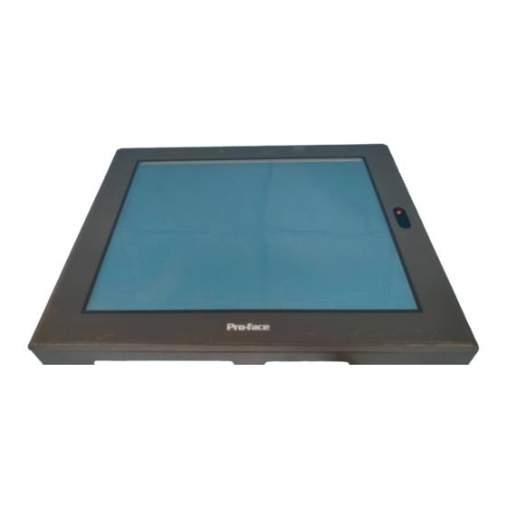
Part Names A : Display A, B C, D B : Touch Panel C : Status LED D : IrDA Interface E : Power Input Terminal Block F : Expansion Unit Interface 1 (EXT1) G : Expansion Unit Interface 2 (EXT2) H : CF Card Cover I : CF Card Slot J : Printer interface (PIO) -
Page 5: General Specifications
Rise T ime : 1 nanosecond Electrostatic Discharge Immunity Contact Discharge, 6kV (IEC61000-4-2 Level 3) *1 If the PS-G's operating temperature exceeds 40 C for an extended period of time, the display quality, i.e, contrast, etc., may degrade. If, however, the oper-... - Page 6 317 mm [12.48 in] x 243 mm [9.57 in.] x 58 mm [2.28 in.] The front face of the PS-G unit, installed in a solid panel, has been tested using conditions equivalent to the standard shown in the specification . Even though the PS-G unit’s level of resistance is equivalent to this standard, oils that should have no effect on the PS-G can possibly harm the unit.
- Page 7 • Be sure to connect pin number 5 (SG) of COM1 and COM2 to the host unit's Signal Ground terminal. • Connect the FG terminal line to the connector shell's PS-G con- nector fastening screw. • FG and SG terminals are internally connected in the PS-G. When connecting to another device, be sure to create an SG shorting loop in your system.
- Page 8 Printer Interface (PIO) This interface conforms to Centronics standards. Pin Arrangement Pin # Signal Condition Direction PSTB Output Strobe Signal PDB0 Output PDB1 Output PDB2 Output PDB3 Output Data 8 bit PDB4 Output PDB5 Output PDB6 Output PDB7 Output Input Acknowledge BUSY Input...
- Page 9 RAS Interface (RAS) Pin Arrangement Pin # Signal Condition ALARM-OUT (-) Alarm Output (-) DOUT (-) General Purpose Output (-) RESET-IN (-) Remote Reset Input (-) DIN0 (-) General Purpose Input 0 (-)* DIN1 (-) General Purpose Input 1 (-)* No Contact RESERVE Reserved...
-
Page 10: Installation
Check that the PS-G’s installation gasket is seated securely into the gasket’s groove, which runs around the perimeter of the panel’s frame. • Before installing the PS-G into a cabinet or panel, check that the instal- lation gasket is securely attached to the unit. - Page 11 [3.94] 100 [3.94] [3.94] • Standard installation for the PS-G unit is in a vertical panel. If the PS- G unit is to be installed in a slanted panel, the panel should not incline more than 30° from the vertical.
- Page 12 Wiring WARNINGS • To avoid an electric shock, check that the PS-G's power supply is completely turned OFF, via a breaker, or similar unit before con- necting the PS-G's power cord terminals to the power terminal block. • The PS600G-T11-J1can accept only AC100V input. If you use power other than AC100V, you can damage both the power supply and the PS-G unit.
-
Page 13: Power Supply Cautions
• To reduce noise, make the power cord as short as possible. Grounding Cautions • When attaching a wire to the PS-G's rear face FG terminal, (on the Power Input Terminal Block), be sure to create an exclusive ground. • FG and SG terminals are internally connected in the PS-G. When connecting to another device, be sure to create an SG shorting loop in your system. -
Page 14: Replacing The Backlight
Replacing the Backlight • The PS-G unit's backlight is user replacable. For an explanation of how to replace the PS-G unit's backlight, please refer to the instruction manual which comes with the replacement backlights (sold separately). • Be sure to use backlight model PS600-BU00.
Need help?
Do you have a question about the PS-G and is the answer not in the manual?
Questions and answers