Sign In
Upload
Manuals
Brands
Parker Manuals
Controller
ACR9000
Parker ACR9000 Motion Controller Manuals
Manuals and User Guides for Parker ACR9000 Motion Controller. We have
3
Parker ACR9000 Motion Controller manuals available for free PDF download: Installation Manual, Programmer's Manual
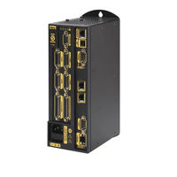
Parker ACR9000 Installation Manual (198 pages)
acr9000 series acr motion controllers
Brand:
Parker
| Category:
Controller
| Size: 3 MB
Table of Contents
Important User Information
2
Table of Contents
4
Table of Tables
6
Table of Figures
8
Important Safety Information
10
Change Summary
11
Chapter 1 Introduction
15
Acr90X0 Controllers-Overview
16
Checking Your Shipment
16
Controller Options
16
Table 1 Ship Kit for Acr90X0 Stand-Alone Controller
16
Accessories
17
Table 2 ACR9000 and ACR9030 Controller Accessories
18
Table 3 ACR9040 Controller Accessories
19
Compatible Parker Hannifin Products
20
About this Guide
20
Assumptions of Technical Experience
21
Technical Support
21
Chapter 2 Specifications
22
Environmental Specifications
23
Table 4 Controller Cooling Requirements
23
Mechanical Specifications
24
Table 5 Controller Weight
24
Table 6 Controller Dimensions
24
Figure 1 ACR9000 and ACR9030 2/4 Axis Dimensions
25
Figure 2 ACR9000 and ACR9030 6/8 Axis Dimensions
25
Electrical Specifications
26
Table 7 Controller Power Requirements
26
Figure 3 ACR9040 Dimensions
26
Table 8 DC Power Connector Pinout
28
External I/O Interface Connectors
29
Table 9 Controller I/O Interface Configurations
29
Figure 4 ACR9000 Stand-Alone Controller 2/4 Axis Front Panel Interfaces
30
Figure 5 ACR9000 Stand-Alone Controller 6/8 Axis Front Panel Interfaces
31
Figure 6 ACR9030 Front Panel Interfaces (2/4 Axis)
32
Figure 7 ACR9040 Front Panel Interfaces
33
Table 10 Connector Pinout, Axes 0−3
35
Table 11 Connector Pinout, Axes 4−7
36
Table 12 Axis Power Electrical Characteristics
37
Figure 8 Equivalent Circuit for Axis Power Source
37
Table 13 Drive Signal Assignments
38
Table 14 Drive Commands
39
Table 15 Outputs-Drive Step and Drive Direction Electrical/Timing Characteristics
40
Table 16 Outputs-Drive AOUT Electrical/Timing Characteristics
40
Table 17 Inputs-Drive Fault Electrical/Timing Characteristics
41
Table 18 Outputs-Drive Enable and Drive Reset Electrical/Timing Characteristics
41
Figure 9 Equivalent Circuit for Drive Step and Drive Direction Outputs
42
Figure 10 Equivalent Circuit for Drive AOUT Outputs
42
Figure 11 Equivalent Circuit for Drive Fault Inputs
43
Figure 12 Equivalent Circuit for Drive Enable and Drive Reset Outputs
43
Figure 13 Equivalent Circuit for Drive Talk Signals
43
Table 19 Encoder Signal Assignments and Supported Features
45
Table 20 Encoder Electrical/Timing Characteristics
45
Figure 14. Equivalent Circuit for Encoder
46
Table 21 Auxiliary Encoder Connector Pinout
47
Table 22 GP Input/Output Connector Pinout (2/4/6/8 Axis Configuration)
48
Table 23 GP Input/Output Connector Pinout (6/8 Axis Configuration)
49
Table 24 GP Inputs 0−11 & 12−23 Connector Electrical/Timing Characteristics
50
Table 25 Trigger Inputs 24−31, 72−79 Connector Electrical/Timing Characteristics
50
Table 26 GP Outputs 32−39 Connector Electrical/Timing Characteristics
51
Figure 15 Equivalent Circuit for GP Inputs/Trigger Inputs Connector
51
Figure 16 Equivalent Circuit for Outputs
52
Table 27 Motion Enable Connector Pinout
53
Table 28 Motion Enable Connector Electrical Timing/Characteristics
53
Figure 17 Equivalent Circuit for Motion Enable Connector
54
Table 29 COM1 Connector Pinout
55
Table 30 Analog Inputs (0-3) Connector Pinout
56
Table 31 Analog Inputs (4-7) Connector Pinout
56
Figure 18 Equivalent Circuit for Differential Analog Inputs Connector
57
Figure 19 Equivalent Circuit for Single-Ended Analog Inputs
57
Table 32 Canopen Connector Pinout
58
Figure 20 Equivalent Circuit for Canopen
59
Table 33 Ethernet Connector Pinout
60
Table 34 ETHERNET Powerlink Connector Pinout
60
Table 35 USB Connector Pinout
61
Chapter 3 Installation
62
Before You Begin
63
Installation Safety Requirements
63
Installation Overview
64
Figure 21 Overview of System Installation
64
Mounting Guidelines
65
Figure 22 Mounting Specifications for ACR9000 and ACR9030 2/4 Axis Configuration
66
Figure 23 Mounting Specifications for ACR9000 and ACR9030 6/8 Axis Configuration
67
Figure 24 Mounting Clearance for ACR9000 and ACR9030 2/4 Axis Configuration
68
Figure 25 Mounting Clearance for ACR9000 and ACR9030 6/8 Axis Configuration
69
Figure 26 Mounting Clearance for ACR9040
70
Cable Installation
71
Figure 27 Loop-Back Diode with Shared Power Supply
72
Table 36 COM1 Transmission Modes
73
Figure 28 RS-232/485 Connector Pin Assignments
73
Figure 29 COM1 Mode Pins (7 and 9)
73
Table 37 COM1 RS-232 Pinout
74
Table 38 RS-485, Four-Wire Connector Pinout
75
Table 39 Drive Connection Cables
76
Table 40 Connection to Aries Pinout
77
Table 41 Connection to Compax3 Pinout
78
Table 42 Connection to Dynaserv Pinout
79
Table 43 Connection to Gemini Servo Pinout
80
Table 44 Connection to Gemini Stepper Pinout
81
Table 45 Connection to Parker Stepper Pinout
82
Table 46 Connection to SLVD and HPD Pinout
83
Table 47 Connection to VIX Pinout
84
Table 48 Connection to Drive with Flying Leads
85
Table 49 Canopen Pinout (Minimum)
87
Figure 30 Canopen Network for Acr90X0
87
Table 50 Canopen Point-To-Point Cable
88
Table 51 Canopen Point-To-Point-Cable Connector Pinout
88
Table 52 Canopen Cables for Multiple-Node Networks
89
Table 53 Estimated Cable and Drop-Line Lengths
89
Table 54 Canopen Bus-Cable Specifications
90
Table 55 Canopen Network Installation Test
90
AC Power Connection
95
DC Power Connection
95
Figure 31 ACR9040 DC Power Connection
95
Chapter 4 Troubleshooting
96
Troubleshooting Guidelines
97
Table 56 Power-Status LED
97
LED Status Indicators
98
Table 57 Axis Status Leds
98
Table 58 Canopen Status LED
99
Table 59 Ethernet Status LED
99
Canopen Connection
100
Ethernet Connection
100
RS-232/RS-485 Communication Problems
101
Table 60 COM1 Connector Pinout
101
Table 61 COM1 Transmission Modes
101
Table 62 Communications Port Error Messages and Resolutions
102
Feedback Device Problems
103
Motion-Related Error Messages
104
Table 63 Motion-Related Error Messages
104
Axis I/O Troubleshooting
105
Figure 32 Motion Enable Input Fault
105
Appendix A SSI Encoders
109
Overview
110
Protocol
110
Timing
111
Table 64 SSI Transfer-Cycle Timing Data
111
Figure 33 SSI Transfer-Cycle Timing
111
Appendix B VM25 Breakout Module
112
Overview
113
Figure 34 VM25 Breakout Module
113
Appendix C VM26 Breakout Module
114
Overview
115
Figure 35 VM26 Breakout Module
115
Appendix D Drive I/O
116
Drive I/O
117
Encoder Input Mode
123
General Purpose and Extended I/O
124
Motion Enable Input
127
Appendix E Canopen
128
Limited Amounts of Nodes and I/O
129
Semi-Automatic Network Configuration
129
Acrobasic Language Access to Canopen I/O
132
Alternate Mapping of Digital I/O
142
Appendix F Drive Talk
143
Quick Startup (ACR9000 and ACR9030)
144
Appendix G Regulatory Compliance
149
System Installation Overview
150
General Safety Considerations
150
General EMC Considerations
150
Installing the Acr90X0 Controller
151
Figure 36 360° Bonding Techniques
152
Table 65 Mains Filter Selection
154
Table 66 Enclosure Mounting Clamps
155
Figure 37 Typical LVD/EMC Installation
156
Figure 38 ACR9000 and ACR9030 2/4 Axis Configuration Panel Layout Dimensions
157
Figure 39 ACR9000 and ACR9030 6/8 Axis Configuration Panel Layout Dimensions
158
Figure 40 ACR9040 Panel Layout Dimensions
159
Regulatory Agencies
160
Standards of Compliance
160
Table 67 Regulatory Agencies
160
Appendix H ETHERNET Powerlink
161
ACR9030 and ACR9040
162
Introduction to ETHERNET Powerlink (EPL)
162
Figure 41 EPL Network Communication
162
Figure 42 EPL Cycle
163
Cabling and SETUP
164
Figure 43 ACR9030 Front Panel
165
Figure 44 ACR9040 Front Panel
166
Figure 45 ACR9030 and Connections to the Aries EPL Drive
167
ACR9030 and ACR9040 Utilization of EPL
168
Support for Cia DSP-402
169
ACR9030 and ACR9040 EPL Commands, Parameters and Flags
170
Table 69 User-Set Network Parameter
170
Table 70 User-Set Node Parameter
170
Table 71 Auto-Populated Network Control and Status Flags
172
Table 72 Control and Status Parameters
173
Table 73 EPL Network States and Corresponding Status Leds
174
Table 74 EPL Operational Errors
174
Table 75 Control Parameters for EPLD0
175
Table 76 Status Parameters for EPLD0
175
Table 77 P37636 (os Download or Reset Progress or Status Control Parameter for EPLD0)
176
Table 78 P4200 (EPLD0 - EPLD3 Digital Inputs)
177
Table 79 P4216 (EPLD0 - EPLD3 Digital Outputs)
178
Access to EPL Drives' Native Command Language
179
Application Scenario
180
Troubleshooting
182
Table 80 Aries EPL Drive Ethernet Status LED Descriptions
183
Figure 46 Ethernet Status Leds
183
Table 81 RJ-45 Connector Pinout
184
Figure 47 Aries EPL Drive EPL Status Leds
184
Table 82 Aries EPL Drive EPL Status Indicator LED Descriptions
185
Table 83 Aries EPL Drive Status Indicator LED Descriptions
187
Figure 48 Drive Status Leds
187
Table 84 Error Messages
190
Figure 49 Hall Connection Diagram
192
Table 85 Configuring Hall Sensors
193
Figure 50 Motor Terminal Voltages (Back EMF) and Hall Sensor Signals
194
Index
195
Advertisement
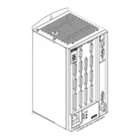
Parker ACR9000 Installation Manual (114 pages)
Stand Alone Controller
Brand:
Parker
| Category:
Controller
| Size: 2 MB
Table of Contents
Technical Assistance
2
User Information
2
Table of Contents
3
Table of Tables
5
Important User Information
9
Safety Warning
9
Change Summary
10
Revision D Changes
10
Revision C Changes
10
Revision B Changes
10
Important Information for Users
9
Chapter 1 Introduction
13
ACR9000 Controllers-Overview
14
Checking Your Shipment
14
Controller Options
14
Table 1 Ship Kit for ACR9000 Stand-Alone Controller
14
Accessories
15
Compatible Parker Hannifin Products
16
About this Guide
16
Table 2 ACR9000 Controller Accessories
16
Assumptions of Technical Experience
17
Technical Support
17
Chapter 2 Specifications
18
Environmental Specifications
19
Cooling
19
Table 3 Controller Cooling Requirements
19
Mechanical Specifications
20
Weight
20
Dimensions
20
Table 4 Controller Weight
20
Table 5 Controller Dimensions
20
Figure 1 ACR9000 2/4 Axis Dimensions
21
Figure 2 ACR9000 6/8 Axis Dimensions
21
Electrical Specifications
22
AC Power Supply Connector
22
Table 6 ACR9000 Power Requirements
22
AC Power Fuse
23
Battery Backup for RAM
23
External I/O Interface Connectors
24
Table 7 Controller I/O Interface Configurations
24
Figure 3 ACR9000 Stand-Alone Controller 2/4 Axis Front Panel Interfaces
25
Figure 4 ACR9000 Stand-Alone Controller 6/8 Axis Front Panel Interfaces
26
Axis Connectors, 0-7
27
Axis Connector Pinout, Axis 0−3
28
Table 8 Connector Pinout, Axes 0−3
28
Axis Connector Pinout, Axis 4−7
29
Table 9 Connector Pinout, Axes 4−7
29
Axis Connector Power Source
30
Figure 5 Equivalent Circuit for Axis Power Source
30
Table 10 Axis Power Electrical Characteristics
30
Drive Function
31
Table 11 Drive Signal Assignments
31
Table 12 Drive Commands
32
Table 13 Outputs-Drive Step and Drive Direction Electrical/Timing Characteristics
33
Table 14 Outputs-Drive AOUT Electrical/Timing Characteristics
33
Table 15 Inputs-Drive Fault Electrical/Timing Characteristics
34
Table 16 Outputs-Drive Enable and Drive Reset Electrical/Timing Characteristics
34
Figure 6 Equivalent Circuit for Drive Step and Drive Direction Outputs
35
Figure 7 Equivalent Circuit for Drive AOUT Outputs
35
Figure 10 Equivalent Circuit for Drive Talk Signals
36
Figure 8 Equivalent Circuit for Drive Fault Inputs
36
Figure 9 Equivalent Circuit for Drive Enable and Drive Reset Outputs
36
Encoder Function
37
Table 17 Encoder Signal Assignments and Supported Features
38
Table 18 Encoder Electrical/Timing Characteristics
38
Auxiliary Encoder Connector
39
Figure 11. Equivalent Circuit for Encoder
39
General Purpose Inputs/Outputs
40
Table 19 Auxiliary Encoder Connector Pinout
40
Table 20 GP Input/Output Connector Pinout (2/4/6/8 Axis Configuration)
41
Table 21 GP Input/Output Connector Pinout (6/8 Axis Configuration)
42
Table 22 GP Inputs 0−11 & 12−23 Connector Electrical/Timing Characteristics
43
Table 23 Trigger Inputs 24−31, 72−79 Connector Electrical/Timing Characteristics
43
Figure 12 Equivalent Circuit for GP Inputs/Trigger Inputs Connector
44
Table 24 GP Outputs 32−39 Connector Electrical/Timing Characteristics
44
Enable Connector
45
Figure 13 Equivalent Circuit for Outputs
45
Table 25 Enable Connector Pinout
46
Table 26 Enable Connector Electrical Timing/Characteristics
46
COM1 Connector
47
Figure 14 Equivalent Circuit for Enable Connector
47
Canopen Connector
48
Table 27 COM1 Connector Pinout
48
Table 28 Canopen Connector Pinout
49
Figure 15 Equivalent Circuit for Canopen
50
Ethernet Connector
51
Table 29 Ethernet Connector Pinout
51
Table 30 USB Connector Pinout
51
USB Connector
51
Chapter 3 Installation
52
Before You Begin
53
Electrical Noise Guidelines
53
Installation Safety Requirements
53
Precautions
53
Installation Overview
54
Recommended Installation Process
54
Figure 16 Overview of System Installation
54
Mounting Guidelines
55
Figure 17 Mounting Specifications for 2/4 Axis Configuration
56
Figure 18 Mounting Specifications for 6/8 Axis Configuration
57
Figure 19 Mounting Clearance for 2/4 Axis Configuration
58
Figure 20 Mounting Clearance for 6/8 Axis Configuration
59
Cable Installation
60
Cable Routing
60
Cable EMC Requirements
60
Enable Connection
60
COM1 Connection
60
Table 31 COM1 Transmission Modes
61
Figure 21 RS-232/485 Connector Pin Assignments
61
Figure 22 COM1 Mode Pins (7 and 9)
61
Table 32 COM1 RS-232 Pinout
62
General Purpose Input/Output Connection
63
Table 33 RS-485, Four-Wire Connector Pinout
63
Axis Connection
64
Table 34 Drive Connection Cables
64
Table 35 Connection to Aries Pinout
65
Table 36 Connection to Compax3 Pinout
66
Table 37 Connection to Dynaserv Pinout
67
Table 38 Connection to Gemini Servo Pinout
68
Table 39 Connection to Gemini Stepper Pinout
69
Table 40 Connection to Parker Stepper Pinout
70
Table 41 Connection to SLVD and HPD Pinout
71
Table 42 Connection to VIX Pinout
72
Table 43 Connection to Drive with Flying Leads
73
Canopen Connection
74
Table 44 Canopen Pinout (Minimum)
75
Figure 23 Canopen Network
75
Table 45 Canopen Point-To-Point Cable
76
Table 46 Canopen Point-To-Point-Cable Connector Pinout
76
Table 47 Canopen Cables for Multiple-Node Networks
77
Table 48 Estimated Cable and Drop-Line Lengths
77
Table 49 Canopen Bus-Cable Specifications
78
Table 50 Canopen Network Installation Test
79
Ethernet Cable Specification
81
Ethernet Connection
81
USB Cable Specification
82
USB Connection
82
Auxiliary Encoder Connection
83
AC Power Connection
83
Chapter 4 Troubleshooting
84
Troubleshooting Guidelines
85
First Troubleshooting Steps
85
General Troubleshooting
85
Table 51 AC-Power-Status LED
85
LED Status Indicators
86
Axis Status Leds
86
Canopen Status LED
86
Table 52 Axis Status Leds
86
Ethernet Status Leds
87
Table 53 Canopen Status LED
87
Table 54 Ethernet Status LED
87
Canopen Connection
88
Ethernet Connection
88
RS-232/RS-485 Communication Problems
89
Table 55 COM1 Connector Pinout
89
Table 56 COM1 Transmission Modes
89
Table 57 Communications Port Error Messages and Resolutions
90
Feedback Device Problems
91
Motion-Related Error Messages
92
Axis I/O Troubleshooting
92
Table 58 Motion-Related Error Messages
92
General Drive I/O
93
Servo Axes
93
Stepper Axes
94
Appendix A SSI Encoders
96
Overview
97
Protocol
97
Timing
98
Table 59 SSI Transfer-Cycle Timing Data
98
Figure 24 SSI Transfer-Cycle Timing
98
Appendix B VM25 Module
99
VM25 I/O Expansion Module
100
Figure 25 VM25 Module
100
Appendix C Regulatory Compliance-UL, EMC, and CE
101
System Installation Overview
102
General Safety Considerations
102
General EMC Considerations
102
Installing the ACR9000 Controller
103
Figure 26 360° Bonding Techniques
104
Table 60 Mains Filter Selection
106
Table 61 Enclosure Mounting Clamps
107
Figure 27 Typical LVD/EMC Installation
108
Figure 28 2/4 Axis Configuration Panel Layout Dimensions
109
Figure 29 6/8 Axis Configuration Panel Layout Dimensions
110
Regulatory Agencies
111
Standards of Compliance
111
Table 62 Regulatory Agencies
111
Index
112
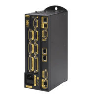
Parker ACR9000 Programmer's Manual (176 pages)
Motion Controllers
Brand:
Parker
| Category:
Controller
| Size: 2 MB
Table of Contents
Table of Contents
3
Table of Contents
5
User Information
5
Change Summary
5
Programming Basics
7
Aliases
7
Program Labels
7
Remarks
8
Command Syntax
8
Example Code Conventions
11
Programs and Commands
12
Kill All Motion Request Vs. Kill All Moves
14
Program Flow
19
Parameters and Bits
24
Parametric Evaluation
27
Basic Setup
31
Before You Begin
31
Startup Programs
39
Resetting the Controller
39
Memory
39
Return to Factory Default
40
Configuration
40
Making Motion
48
Four Basic Categories of Motion
48
Move Types
49
What Are Motion Profiles
53
Interaction between Motion Profilers
54
Velocity Profile Commands
58
Coordinated Moves Profiler
63
Jog Profiler
66
Gear Profiler
76
Cam Profiler
77
Homing
77
Servo Loop Fundamentals
87
Setpoint Compensation
87
Following Error
88
Application Examples
90
Basic Motion
90
Enable Drive
91
EPL Network
92
Homing
93
Open Sample
96
Teach Array
97
Binary Host Interface
99
Binary Data Transfer
99
Binary Data Packets
101
Binary Parameter Access
103
Binary Peek Command
106
Binary Poke Command
107
Binary Address Command
108
Binary Parameter Address Command
110
Binary Mask Command
111
Binary Parameter Mask Command
112
Binary Move Command
113
Binary SET and CLR
120
Binary FOV Command
121
Binary ROV Command
123
Application: Binary Global Parameter Access
125
Additional Features
127
Canopen
127
Drive Talk
141
Inverse Kinematics
147
Troubleshooting
149
Problem Isolation
149
Information Collection
149
Troubleshooting Table
150
Error Handling
158
Appendix
167
IP Addresses, Subnets, & Subnet Masks
167
Output Module Software Configuration Examples
172
Index
175
Advertisement
Advertisement
Related Products
Parker ACR9030
Parker ACR9040
Parker ACR Series
Parker Hannifin ACR1505
Parker ACR7000 Series
Parker ACR74V-A5V4C1
Parker ACR78V-A5V4C1
Parker ACR8000
Parker AC30 series
Parker AC890PX Series
Parker Categories
Controller
Control Unit
Industrial Equipment
Dryer
DC Drives
More Parker Manuals
Login
Sign In
OR
Sign in with Facebook
Sign in with Google
Upload manual
Upload from disk
Upload from URL