RUPTELA FM-Pro3 Manual Manual
Gps/ gsm terminal
For more information, please visit ruptela.com
Table of Contents
Advertisement
Advertisement
Table of Contents

Related Manuals for RUPTELA FM-Pro3


Summary of Contents for RUPTELA FM-Pro3
- Page 1 RUPTELA GPS/ GSM Terminal Model: FM-Pro3 MANUAL v1.1...
-
Page 2: Table Of Contents
1.3. ACRONYMS AND TERMS USED IN DOCUMENT 2. BASIC DESCRIPTION 2.1. PACKAGE CONTENTS 2.2. ADDITIONAL ACCESSORIES 2.3. BASIC CHARACTERISTICS 2.4. TECHNICAL FEATURES 2.5. FM-PRO3 DIMENSIONS 2.6. LED STATUSES 2.7. PINOUT, CONNECTION 2.8. SPECIAL FEATURES 3. INSTALLATION INSTRUCTIONS 3.1. MODULE INSTALLATION... -
Page 3: Introduction
1. INTRODUCTION 1.1. SAFETY REQUIREMENTS All the associated (additional) equipments as PC, batteries, sensors and others, shall meet the requirements of standard EN60950-1. Do not disassemble the Terminal. If the enclosure of Terminal is damaged, or the insulation of wires is damaged, first of all unplug the 10 pins connector from the Terminal carefully. - Page 4 1A/500mA. The allowed voltage range for battery: 10…32V DC. To avoid mechanical damage, it is advised to transport the Terminal FM-Pro3 in an impact- proof package. Before connecting the wires of 12 pins plug to the vehicle, ensure that 10 pins plug is sectional area of mounting wires is at disconnected from the Terminal.
-
Page 5: Legal Notice
• SMS – Short Message Service. • AC/DC – Alternating Current/Direct Current. • Record – Data stored in FM-Pro3 memory. Data contains GPS and I/O Information. • FMS – an optional standard interface of different truck manufacturers. • Simplified RS232 - connection standard between different pieces of equipment. Simplified RS232 has only Rx and Tx lines. -
Page 6: Basic Description
2. BASIC DESCRIPTION FM-Pro3 is a Terminal with GPS / GSM connectivity, which is able to determine the object’s coordinates and transfer them via the GSM network. This Terminal is perfectly suitable for applications where location acquirement of remote objects is needed. It is important to mention that FM-Pro3 has additional inputs and outputs, which lets controlling and monitoring other devices on remote objects. -
Page 7: Package Contents
2.1. PACKAGE CONTENTS Figure2. FM-Pro3 device, Power, I/O cables and GPS antenna. The FM-Pro3 device is supplied to the customer in a cardboard box containing all the equipment that is necessary for operation. The package contains: • The FM-Pro3 device. -
Page 8: Basic Characteristics
2.3. BASIC CHARACTERISTICS Inputs / Outputs: IO1 – 10 pin (2x5 plug): IO2 – 12 pin (2x6 plug): Paired connections scheme: Other Inputs / Outputs are not paired. Also two spare Chassis pins can be paired with any I/O, they are only for easier mounting. -
Page 9: Technical Features
2.4. TECHNICAL FEATURES: Power supply External Battery Ratings: Ublox module (with external GPS antenna) +12/24V 1A/500mA GPRS/GSM Simcom module (with Internal battery Ratings: internal GPS antenna) Li-Po 3.7V 800 mAh Motion Micro vibration sensor sensor Fuses External fuse (mounted LED’s GPS fix led, into +BAT wire): GSM led,... -
Page 10: Fm-Pro3 Dimensions
2.5. FM-PRO3 DIMENSIONS... -
Page 11: Led Statuses
2.6. LED STATUSES: GPS LED When GPS signal is not received or GPS signal is not accurate, the GPS LED is blinking as follows: When accurate GPS signal is received, the GPS LED is blinking as follows: GSM LED When GSM signal is not received, GSM led is blinking: When device has good GSM signal, but no GPRS, LED is blinking: When device has good GSM signal and it is connected to GPRS, then LED is blinking:... - Page 12 Peripheral LED To the FM-Pro3 terminal can be attached up to 3 peripheral interfaces. So there is 3 different type of blinking when one or other peripheral is connected. When there is no peripheral attached, LED wont blink at all:...
-
Page 13: Pinout, Connection
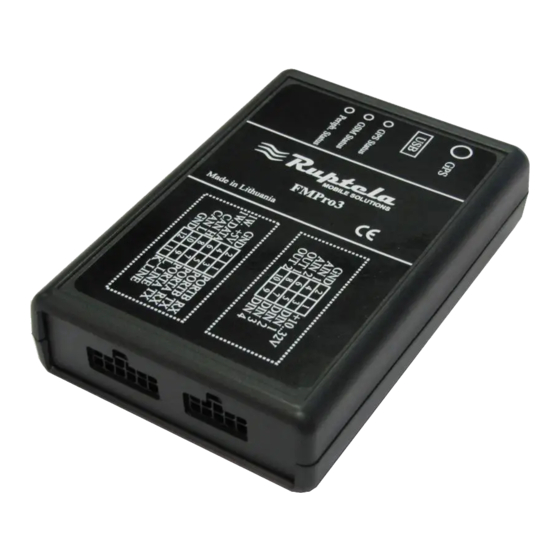
2.7. PINOUT, CONNECTION: FM-Pro3 standard plugs, 12 and 10 pins. Standard FM-Pro3 12 pins plug description: Pin name Description PortB RX Port B receive signal Chassis The frame or chassis of a car. PortB TX Port B transit signal OUT +5V +5V output for Dallas 1-Wire®... -
Page 14: Special Features
2.8. USB Description name Data - Data + Chassis 2.9. SPECIAL FEATURES: • Any element event triggers (external sensor, input, speed, temperature, etc.) • Smart profile switching (GSM operator or any element dependant) • Highly configurable data acquisition and sending •... - Page 15 3. MOUNTING RECOMMENDATIONS Connecting Wires • Wires should be connected while module is not plugged in. • Wires should be fastened to the other wires or non-moving parts. Try to avoid heat emitting and moving objects near the wires. • The connections should not be seen very clearly. If factory insulation was removed while connecting wires, it should be applied again.
-
Page 16: Module Installation
3.1. MODULE INSTALLATION • Module should not be seen or easily reached. • Module should be firmly fixed to the surface or cables. • Module cannot be fixed to heat emitting or moving parts. • SIM card should be inserted in the module while the connector is plugged off (while module has no power). - Page 17 PAY YOUR ATTENTION THAT FM-PRO3 DEVICE HAS INTERNAL GSM ANTENNA! To ensure good FM-Pro3 GPS and GSM connectivity it is strongly recommended to install device not less than 50mm from any metal shield parts as it is shown in the picture below.
- Page 18 Installation near metal shield parts as shown in the picture below does not guarantee good GSM and GPS connectivity.
Need help?
Do you have a question about the FM-Pro3 and is the answer not in the manual?
Questions and answers