RUPTELA FM-Eco4 T Series User Manual
For more information, please visit ruptela.com
Hide thumbs
Also See for FM-Eco4 T Series:
- User manual (33 pages) ,
- Quick start manual (4 pages) ,
- User manual (31 pages)
Table of Contents
Advertisement
Quick Links
Advertisement
Table of Contents

Related Manuals for RUPTELA FM-Eco4 T Series


Summary of Contents for RUPTELA FM-Eco4 T Series
- Page 1 FM-Eco4 T Series User Manual v1.0 2020-02-14...
-
Page 2: Table Of Contents
Table of Contents Introduction ........................4 Purpose of This Document ..................4 Legal Information ...................... 4 Contact Information ....................4 Document Changelog ....................5 Safety Information..................... 6 Notations ........................7 Acronyms and Abbreviations ..................8 References ........................ 9 Product Information ....................... 10 About ........................ - Page 3 Closing the Device ....................23 Cable Connection ....................24 4.4.1 12 Pin Cable Connection ..................24 4.4.2 USB Cable Connection ..................24 Device Preparation (IP67 Housing) .................. 25 Opening the Device ....................25 Inserting a SIM Card ....................26 Cable Connection ....................27 5.3.1 12 Pin Cable Connection ..................
- Page 4 Required Tools ......................43 Installation Recommendations .................. 43 8.3.1 External GNSS Antenna Positioning ..............44 Wiring Diagram (Regular Housing) ................45 Wiring Diagram (IP67 Housing) ................46 Installation Check-up ....................47 Troubleshooting ...................... 47 8.7.1 gsminfo ......................47 8.7.2 getapn ......................48 8.7.3 coords......................
-
Page 5: Introduction
Introduction 1.1 Purpose of This Document The purpose of this user manual is to provide information about the FM-Eco4 T Series devices. This user manual describes the main features of the device and how to use it. Detailed descriptions of functionalities and peripheral devices can be found on our documentation website: doc.ruptela.lt. -
Page 6: Document Changelog
1.4 Document Changelog Version Date Modification 2020-02-14 Initial draft. -
Page 7: Safety Information
Caution! If an incorrect type of battery is used for replacement, there is a high explosion risk. Dispose of used batteries according to the environmental requirements. For configuration use cables that were purchased from Ruptela. Ruptela is not responsible for any harm or damage caused while using the wrong cables. -
Page 8: Notations
1.6 Notations The following notations are used in this document to highlight important information: Bold text Used to indicate user interface elements or for emphasis. Italic text Used to indicate items that belong to a list and can be selected. Note Used to highlight important information or special conditions.... -
Page 9: Acronyms And Abbreviations
1.7 Acronyms and Abbreviations AC/DC – Alternating current/Direct current APN – Access Point Name DIN – Digital Input DOUT – Digital Output HDOP – Horizontal Dilution of Precision GLONASS – Global Navigation Satellite System GMT – Greenwich Mean Time GNSS – Global Navigation Satellite System GPRS –... -
Page 10: References
1.8 References Datasheets: https://doc.ruptela.lt/pages/viewpage.action?pageId=33357966 Quick Start Guides: https://doc.ruptela.lt/pages/viewpage.action?pageId=33357966 Device Center: https://doc.ruptela.lt/display/AB/Device+Center Advanced configuration manual: https://doc.ruptela.lt/pages/viewpage.action?pageId=33357966 Firmware and configurator files: https://doc.ruptela.lt/pages/viewpage.action?pageId=33357962 Microsoft Framework: https://www.microsoft.com/en-us/download/details.aspx?id=53344 VCOM drivers: https://doc.ruptela.lt/display/AB/FM4+drivers... -
Page 11: Product Information
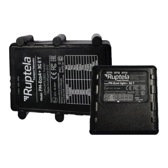
Product Information 2.1 About FM-Eco4 T is a low cost, low power consumption basic tracking device. It acquires its position with a GNSS signal and transfers data to a server via cellular GSM/GPRS/UMTS networks. The FM-Eco4 T Series devices come in the following variations: •... -
Page 12: Device Overview (Regular Housing)
2.2 Device Overview (Regular Housing) 12 Pin port Mini USB port Indication LEDs 2.3 Device Overview (IP67 Housing) 12 Pin cable GNSS antenna cable (FM-Eco4+ 3G E T only) Indication LEDs... -
Page 13: Key Features
2.4 Key Features • Real-time data from GPS and accelerometer • Driver behaviour monitoring (Eco-Drive) • Driver identification • Temperature monitoring • Remote ignition blocking • Internal geozones • Jamming detection • Commands and configuration via SMS • Supports additional sensors... -
Page 14: Package Contents (Regular Housing)
2.5 Package Contents (Regular Housing) The device is packed in a cardboard box. The package contains the following items: 1. The device itself 2. A 12 Pin cable By default, no SIM card is provided in the package. SIM cards can be obtained from your local phone operator.... -
Page 15: Package Contents (Ip67 Housing)
2.6 Package Contents (IP67 Housing) The device is packed in a cardboard box. The package contains the following items: 1. The device itself 2. An external GNSS antenna (FM-Eco4+ 3G E T only) 3. A signal cable By default, no SIM card is provided in the package. SIM cards can be obtained from your local phone operator.... -
Page 16: Certifications
2.7 Certifications The FM-Eco4 T Series devices have passed quality tests and comply with the following certifications: Certification of Economic Commission for Europe is the European E-Mark conformity mark issued by the transport sector, indicating that the product complies with relevant laws and regulations or directives. - Page 17 GOST refers to a set of technical standards maintained by the Euro- Asian Council for Standardization, Metrology and Certification GOST (EASC), a regional standards organization under the auspices of the Commonwealth of Independent States (CIS). The device is protected from total dust ingress. The device is protected from immersion in depths from 15 centimeters to 1 meter.
-
Page 18: Technical Information
Technical Information 3.1 Indication LED Patterns Pattern Description GNSS Once every second Accurate signal Once every 0.4 seconds No signal Once every 4 seconds Accurate GSM and GPRS signal Once every second Accurate GSM signal, no GPRS Once every 0.2 seconds No signal Always on Link with the server is open... -
Page 19: Physical Characteristics
3.3 Physical Characteristics Dimensions 64.5 x 61 x 22 mm (regular housing) 95 x 76.4 x 28.8 mm (IP67 housing) Weight 65 ± 5 g (FM-Eco4+ light 3G T) 148 ± 5 g (FM-Eco4+ 3G T) 185 ± 5 g (FM-Eco4+ 3G E T) Housing material Plastic Connector... -
Page 20: Power Consumption @ 12 V Dc
3.4.3 Power Consumption @ 12 V DC FM-Eco4 light+ 3G T FM-Eco4+ 3G T FM-Eco4+ 3G E T Operating Idle mode: 33 mA Active mode (peak @ GSM): 138 mA (battery fully charged) Sleep mode: 6.3 mA Deep sleep mode: 4 mA 3.4.4 Connectivity FM-Eco4 light+ 3G T... -
Page 21: Digital Inputs
3.5.3 Digital Inputs Pins DIN1, DIN2, DIN3 (invertible), DIN4 (invertible) Purpose To monitor the values of various peripherals Parameters Voltage range: 0 – 30 V DC Voltage threshold: 4 V DC (250 mV DC if in ground mode) Applications Ignition detection Various sensors 3.5.4 Digital Outputs Pins... -
Page 22: Device Preparation (Regular Housing)
Device Preparation (Regular Housing) For the device to work, you first need to insert a SIM card. To do so, open the device housing and perform the actions described below. 4.1 Opening the Device Use a flat head screwdriver to open the plastic housing. Insert the screwdriver between the top and bottom parts of the housing and lift the top part up as shown in the image below. -
Page 23: Inserting A Sim Card
4.2 Inserting a SIM Card Insert your SIM card into the device as shown in the image below. The microchip must be facing down. All SIM card security codes must be disabled, otherwise the SIM card will not work with the device.... -
Page 24: Closing The Device
4.3 Closing the Device To close the device, you first need to reinsert the PCB if it was taken out of the housing and attach it to the holding pins. Reinsert the PCB in the following order: 1. Orient the PCB so that it is facing up 2. -
Page 25: Cable Connection
4.4 Cable Connection 4.4.1 12 Pin Cable Connection Connect the 12 Pin cable to the 12 Pin Micro-Fit port on the device as shown in the image below. The cable can be connected in only one way. 4.4.2 USB Cable Connection Connect the USB cable to the mini USB port as shown in the image below. -
Page 26: Device Preparation (Ip67 Housing)
Device Preparation (IP67 Housing) For the device to work, you first need to insert a SIM card. To do so, open the device housing and perform the actions described below. 5.1 Opening the Device Use a “+” type screwdriver to open the plastic housing. Unscrew the 6 screws at the bottom of the device as shown in the image below. -
Page 27: Inserting A Sim Card
5.2 Inserting a SIM Card Insert your SIM card into the device as shown in the image below. The microchip must be facing down. All SIM card security codes must be disabled, otherwise the SIM card will not work with the device.... -
Page 28: Cable Connection
5.3 Cable Connection 5.3.1 12 Pin Cable Connection The 12 Pin cable is connected out of the box, you do not need to reconnect it. 5.3.2 USB Cable Connection Connect the USB cable to the mini USB port as shown in the image below. The cable can be connected in only one way. -
Page 29: External Gnss Antenna Cable Reconnection (Fm-Eco4+ 3G E T Only)
5.3.4 External GNSS Antenna Cable Reconnection (FM-Eco4+ 3G E T only) In some cases, you may need to disconnect the antenna from the device during installation. It is important to disconnect and reconnect the antenna properly to maintain the integrity of the housing. Follow these steps to disconnect the antenna: 1. - Page 30 Afterwards, follow these steps to reconnect the antenna: 1. Insert the antenna cable into the housing. 2. Reconnect the antenna cable to the PCB. 3. Mount the PCB onto the holding points (1) (2), 4. Put the top on and screw in the screws (1). while firmly placing the cable into its fixing point Carefully insert the gasket (2) into its place, make (3).
-
Page 31: Driver Installation
Driver Installation Before configuring the device, you must install the VCOM drivers and the latest version of Microsoft Framework, otherwise your computer will not recognize the device. You can download the VCOM drivers from our documentation website: VCOM drivers. Select a suitable driver file for your operating system as shown in the image below. Only Windows 7/8/10 operating systems are supported.... -
Page 32: Device Configuration
• Update the device firmware Download the Device Center from our documentation website: doc.ruptela.lt. You can also find a detailed description of the Device Center in the User manual section. Extract the downloaded archive to your desired location. Launch DeviceCenter.exe. -
Page 33: Starting The Configuration
7.2 Starting the Configuration After launching the Device Center, click Configure device in the main menu. If the VCOM drivers are installed, you will be directed to the configuration type selection menu. Click Connect device. - Page 34 Select your device in the device selection menu by clicking on it. Click Next to continue.
-
Page 35: Configuration Menu
7.2.1 Configuration Menu After device selection, you will be directed to the main configuration menu. This menu has the following elements: 1. An Advanced mode button – opens the advanced configurator 2. Device info – displays information about the connected device 3. -
Page 36: Configuration Basics
7.3 Configuration Basics For the device to be fully operational, it must have a configuration file uploaded to it. A configuration file contains information on what functionalities are active, how they are configured and what kind of data is included in records. You can upload the same configuration file to multiple devices, making it easy to receive identical data from all your vehicles. -
Page 37: Loading A Configuration From A Device
7.3.4 Loading a Configuration from a Device Click Load from device in the button bar. The configuration will be loaded from the connected device. Loading a configuration from a device will discard any changes to the existing configuration. 7.3.5 Saving a Configuration to a Device Click Save to device in the button bar. -
Page 38: Essential Settings
7.4 Essential Settings Only the settings that are essential to use the device are described in this document. For a detailed description of all the additional functionalities, please refer to the Device Center advanced configuration user manuals. 7.4.1 Server Settings Open the Connection settings section. -
Page 39: Apn Settings
7.4.2 APN Settings Open the Connection settings section. APN settings are needed to connect to the internet. The device will not send any data without APN settings. They must be provided by your SIM card provider. Name The APN name. This parameter is mandatory for most SIM cards. Consult with your SIM card provider for more information. -
Page 40: Engine Detection And Data Collection Settings
7.4.3 Engine Detection and Data Collection Settings Open the Engine detection and data collection section. Select an engine state detection method and set the tracking accuracy. When the engine is turned on, records are generated more often. The detected engine state is also used by other functionalities, such as driver registration. Engine state detection How the device detects whether the engine is turned on. -
Page 41: Advanced Configuration
Advanced mode in the top bar at any time. A detailed description of the advanced configurator is available at doc.ruptela.lt. Close the advanced configurator to return to the Device Center. 7.6 Configuration via SMS Commands Alternatively, the device can be configured using SMS commands. -
Page 42: Updating Firmware
7.7 Updating Firmware We highly recommend using the newest firmware to take advantage of our newest functionalities and improvements. Device firmware can be updated in the following ways: • Automatically when using a configurator that is newer than the firmware •... -
Page 43: Updating Firmware Manually
7.7.3 Updating Firmware Manually This feature requires the use of the advanced configurator. To update firmware manually, open the advanced configurator. Click Connect and Send FW in the main configurator menu. Locate your firmware file and click Open. The firmware update process will start. -
Page 44: Installation In Vehicle
Installation in Vehicle 8.1 Installation Method To install the device, you need to connect it to a power supply and an ignition source. They may be found in the following locations: • The OBD diagnostic port • The fuse box 8.2 Required Tools Before starting the installation, make sure you have the following tools: •... -
Page 45: External Gnss Antenna Positioning
Correct Incorrect Correct Incorrect 8.3.1 External GNSS Antenna Positioning It is recommended to place the GNSS antenna behind the dashboard as close to the windshield as possible and further away from the doors. It must be uncovered and facing up as shown in the picture below. -
Page 46: Wiring Diagram (Regular Housing)
8.4 Wiring Diagram (Regular Housing) Power input: 6-31.5 V DC. It is mandatory to use an external automotive 1 A fuse. -
Page 47: Wiring Diagram (Ip67 Housing)
8.5 Wiring Diagram (IP67 Housing) Power input: 6-31.5 V DC. It is mandatory to use an external automotive 1 A fuse. -
Page 48: Installation Check-Up
8.6 Installation Check-up 1. Take several minutes to review the installation, check that everything is connected properly. 2. Turn on the vehicle ignition and wait for several minutes. 3. Check that the required data is received by sending an SMS command or checking your fleet management platform. -
Page 49: Getapn
8.7.2 getapn If the device is connected to GSM and GPRS networks but does not send any data, check the APN getapn and connection settings with the SMS command. password getapn Command syntax: APN: banga User: PSW: IP1: 92.62.134.38 Port1: 9021 IP2: 195.14.173.3 Port2: Response example: 9000 TCP/UDP: 0 The parameters and their values are self-explanatory, except for TCP/UDP. -
Page 50: Reset
8.7.4 reset reset When all else fails, use the SMS command to restart the device. Configuration parameters will not be lost. password reset Command syntax: Resetting device Response example:...
Need help?
Do you have a question about the FM-Eco4 T Series and is the answer not in the manual?
Questions and answers