RUPTELA FM-Pro4 User Manual
For more information, please visit ruptela.com
Hide thumbs
Also See for FM-Pro4:
- User manual (37 pages) ,
- User manual (42 pages) ,
- Quick start manual (4 pages)

Related Manuals for RUPTELA FM-Pro4


Summary of Contents for RUPTELA FM-Pro4
- Page 2 Preface ............................2 Use of this document ....................... 2 Document change log....................... 2 Introduction ............................ 3 Purpose............................ 3 Acronyms ..........................3 Legal Information ........................3 Safety ............................3 References ..........................5 Device description ........................... 6 About ............................6 Package contents ........................6 Physical characteristics ......................
- Page 3 This document provide required information for proper device handling, preparation, configuration and installation to vehicle. This document has linear structure – from opening box to recommendations how to install device to vehicle. However it is not overfilled with unnecessary information. You will find basic description of functions and actions to start using device with reference to extensive content descriptions.
- Page 4 Copyright © 2014 Ruptela. All rights reserved. Reproduction, transfer, distribution or storage of parts or all of the contents in this document in any form without the prior written permission of Ruptela is prohibited. Other products and company names mentioned in this document are trademarks or trade names of their respective owners.
- Page 5 Any installation and/or handling during a lightning storm is prohibited. Use cables for configuration purchased from Ruptela. Ruptela is not responsible for any harm caused by using wrong cables for PC ↔ FM Terminal connection.
- Page 6 This document is designed to work in conjunction with other documents. This way documentation is kept light, not overfilled with unnecessary information. All additional and extensive explanation can be found in referenced documentation: FM-Pro4 Datasheet – Technical data of FM-Pro4 device. Can be acquired from support@ruptela.com Quick start guide –...
- Page 7 Ruptela‘s FM-Pro4 is 4 generation advanced, low power consumption, but powerful tracking device. It acquires its position by GPS/GLONASS signal and transfer data to server via GPRS cellular network. FM-Pro4 new features compared to PRO3: • Lower power consumption •...
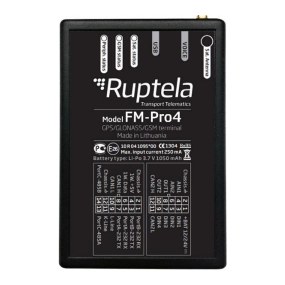
- Page 8 Enclosure dimensions 111 x 75 x 25 mm Indication 3 LEDs: Sat. status, GSM status, Periph. status Housing Plastic External elements GPS/GLONASS all-in-one antenna Configuration interface Connectors 12 & 14 PINs Deep sleep mode 16 mA @ 12 V Normal mode Max.
- Page 9 10-32 V Power supply 12/24 V (range: 10-32 V) Chassis Black Ground connection DIN1 Pink Digital input, threshold 4 V AIN1 Gray Analogue input (range: 0-30 V) DIN2 Blue Digital input, threshold 4 V AIN2 Green Analogue input (range: 0-30 V) DIN3 White Digital input, threshold 4 V...
- Page 10 There are several peripheral accessories that can be mounted with FM-Pro4 device. With peripherals you can get even more features and extend application. All available peripherals can be purchased from Ruptela. Please contact your manager for details. 1-Wire power maximum power output is 200 mA @ 5 V FM-Pro4 device supports RS232, RS485, 1-wire and CAN interfaces.
- Page 11 FM-Pro4 devices have passed quality tests and comply with following certifications: • E-Mark (E26 10 R 04 1095*00) • CE (CE 1304) • RoHS When GPS/GLONASS signal is not received or GPS/GLONASS signal is not accurate, the GPS LED is blinking...
- Page 12 When the FM-Pro4 terminal has GSM signal and it is sending data via GPRS, LED is blinking: To the FM-Pro4 terminal can up to 3 peripheral devices attached (e.g. CAN, LLS, 1-wire). So there are 4 different types LED states when peripheral device is connected. When there is no peripheral attached,...
- Page 13 Virtual COM port driver installation is mandatory, only then your PC will recognize the FM- FM-Pro4 device that was connected to the USB port. You can download newest drivers from our FTP server (VCOM drivers). Choose correct archive file with drivers for your OS version and download it to your PC.
- Page 14 In the next window select “Next” [4.]. Wait for the setup to complete the installation and click “Finish” [5.]. Driver is now installed and ready to use.
- Page 15 Please log in to our FTP server and download sample configuration and newest configurator . Also you need newest Microsoft Framework. Operating system requirements: • MS Windows XP/Vista/7/8 Start VCP.exe from configurator folder. 1. Select Pro4 2. Click File → Open CFG In dialog window, browse sample configuration file you downloaded from FTP.
- Page 16 Enter APN settings: APN name, User login and Password (if login and password needed). If you choose to enable Lock FM device to the SIM card check-box you will be required to enter SIM card’s PIN code every time you try to connect to the device via USB cable. As long as it is checked you will not be able to use different SIM cards with this device.
- Page 17 Configuration tool is quite similar to 3 generation devices. Overview of configuration is described in sections. File menu gives you access to control configuration files. Choose New/Save/Open CFG to perform corresponding action. CFG means full configuration file. Tools menu contain language selection: English or Russian. Save/Open DIFF allow you to create DIFF file.
- Page 18 First part of configuration tool is global settings. Global include connection settings and other settings independent from profile settings – global settings are same for all profiles. UDP protocol is less reliable than TCP but also uses less traffic. TCP however use more internet traffic but is more reliable.
- Page 19 Total of seven different statuses are available: 1. Ready – PIN code is known or PIN code check is disabled. GSM/GPRS modem can operate normally. 2. Error – Represents a wide range of possible problems. Common reason would be old FW version, which does not support SIM commands.
- Page 20 With Authorized numbers you can apply password for SMS commands. Also you can enter specific numbers who can send commands to device. If you check Enable list for voice calls entered numbers will be able to call to device for conversation or for listen-in purposes.
- Page 21 Driver registration is used to authorize vehicle start, identify driver and account working hours. Full functionality description can be found at our FTP, Driver registration. Geozone setting allow to use internal geozones, configured directly into device. Full description can be found at our FTP, Internal geozones.
- Page 22 With Data sending settings you can configure data sending frequency and conditions. Enable check box must be enabled. Min. records – Minimum number of records required to establish connection to server. If device detects less records than entered, link will not be opened to server. ...
- Page 23 GSM only – device operates only in 2G mode. UMTS only – device operates only in 3G mode. FM-Pro4 devices with hardware versions that do not have UG96 modem operate only in 2G mode. For these devices “Auto”, “GSM only” and “UMTS only” options have no effect.
- Page 24 Operator list … 3 Profile tab – operators list in this tab allows selection of operators used in current profile. If operator that is in the list was not found, then device will search for other operator in the list. If no operators were found, device will switch to the next profile.
- Page 25 Received trouble codes can be monitored with the help of "GSM trouble codes" IO parameter. This functionality might be compatible and might be supported with 3G modems used in Ruptela's FM devices. Key point about the temporary black list: o Ban period is configurable. When all operators get into the ban list, ban list is cleared.
- Page 26 2. Enable this check box otherwise slot will remain empty 3. Parameter list. Choose parameter you want to enable for selected slot. One parameter can be enabled only one time. 4. Used with hysteresis mode, see 7.c 5. Used with hysteresis mode, see 7.c 6.
- Page 27 Bellow you will find checkboxes for the CAN and CAN2 interfaces. CAN – if you put a tick in the 1st CAN interface checkbox, then a dropdown list appears, where you can choose one of the following: FMS - for vehicle CANbus (FMS) information reading. ...
- Page 28 Calc HRLFC - enables fuel consumption recalculation from fuel rate for FMS CANbus mode. Recalculation works only when high resolution fuel consumption data from CANbus is not available. Active – If this checkbox is enabled, device will do both, receive and send data to the vehicle’s onboard computer.
- Page 29 DOUT1 and DOUT2 – dropdown lists let you choose one of the following: Disabled, LED, Buzzer, Blocking, GSM jamming block. More information available at our FTP server: FTP link All integration related questions and documentation can be acquired from Ruptela technical support: support@ruptela.com...
- Page 30 Device must be fitted with double sided stick tape! It is recommended to place GPS/GLONASS antenna behind the dashboard as close to the window as possible. www.ruptela.lt Main Support no.: +370 5 2045030 Polish Support no.: +48 22 2092532 Ukrainian Support no.: +380 947 107319...
Need help?
Do you have a question about the FM-Pro4 and is the answer not in the manual?
Questions and answers