RUPTELA FM-Eco4 T User Manual
For more information, please visit ruptela.com
Advertisement
Quick Links
Advertisement

Related Manuals for RUPTELA FM-Eco4 T


Summary of Contents for RUPTELA FM-Eco4 T
- Page 1 FM-Eco4 T User Manual...
-
Page 2: Table Of Contents
Table of Contents Table of Contents..............................1 EN FM-Eco4 T Series User Manual........................2 FM-Eco4 T Product Information......................6 FM-Eco4 T Technical Information....................12 FM-Eco4 T Device Preparation (Regular Housing)................19 FM-Eco4 T Device Preparation (IP67 Housing)................22 FM-Eco4 T Device Configuration..................... 26 FM-Eco4 T Installation in Vehicle....................42... -
Page 3: Fm-Eco4 T Series User Manual
EN FM-Eco4 T Series User Manual Purpose of This Document The purpose of this user manual is to provide information about the FM-Eco4 T Series devices. This user manual describes the main features of the device and how to use it. - Page 4 Caution! If an incorrect type of battery is used for replacement, there is a high explosion risk. Dispose of used batteries according to the environmental requirements. For configuration use cables that were purchased from Ruptela. Ruptela is not responsible for any harm or damage caused while using the wrong cables.
- Page 5 Used to mark actions that require caution when handling the product. Warning Used to mark actions that may cause irreversible damage if performed incorrectly. Suggestions on how to proceed. Acronyms and Abbreviations AC/DC – Alternating current/Direct current APN – Access Point Name DIN –...
- Page 6 References Datasheets: https://doc.ruptela.com/articles/#!project-tracking-devices/fm-eco4t-datasheets Quick Start Guides: https://doc.ruptela.com/articles/#!project-tracking-devices/fm-eco4t-quick-start- guides Device Center: https://doc.ruptela.com/articles/#!downloads-publication/device-center Advanced configuration manual: https://doc.ruptela.com/articles/#!tracking-devices- publication/advanced-configurator-user-manual Firmware and configurator files: https://doc.ruptela.com/articles/#!downloads-publication/downloads- home Microsoft Framework: https://dotnet.microsoft.com/download/dotnet-framework/net48 VCOM drivers: https://doc.ruptela.com/articles/#!downloads-publication/tracking-device-drivers...
-
Page 7: Fm-Eco4 T Product Information
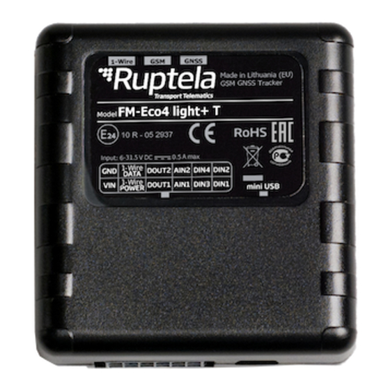
1.1 FM-Eco4 T Product Information About FM-Eco4 T is a low cost, low power consumption basic tracking device. It acquires its position with a GNSS signal and transfers data to a server via cellular GSM/GPRS/UMTS networks. The FM-Eco4 T Series devices come in the following variations: ·... - Page 8 12 Pin port Mini USB port Indication LEDs Device Overview (IP67 Housing) 12 Pin cable GNSS antenna cable Indication LEDs GNSS antenna cable applicability FM-Eco4+ T FM-Eco4+ E T FM-Eco4+ 3G T FM-Eco4+ 3G E T FM-Eco4+ RS T FM-Eco4+ RS E T FM-Eco4+ 3G RS T...
- Page 9 · Internal geozones · Jamming detection · Commands and configuration via SMS · Supports additional sensors Package Contents (Regular Housing) The device is packed in a cardboard box. The package contains the following items: 1. The device itself 2. A 12 Pin cable By default, no SIM card is provided in the package.
- Page 10 By default, no SIM card is provided in the package. SIM cards can be obtained from your local phone operator. Certifications The FM-Eco4 T Series devices have passed quality tests and comply with the following certifications: Certification of Economic Commission for Europe is the European E-Mark conformity mark issued by the transport sector, indicating that the...
- Page 11 CE is a certification mark that ensures conformity with health, safety and environmental protection standards for products sold within European CE/RED Economic Area (EEA). The Radio Equipment Directive, or RED, covers the standards for wireless devices. (47 CFR part 15, subpart B) The FCC Declaration of Conformity is a certification mark employed on electronic products manufactured or sold in the United States which certifies that the electromagnetic interference from the device is under limits approved by the Federal Communications...
- Page 12 The device is protected from immersion in depths from 15 centimeters to 1 meter. The following devices have an IP67 rating: · FM-Eco4+ 3G T · FM-Eco4+ 3G E T · FM-Eco4+ T · FM-Eco4+ E T · FM-Eco4+ E RS T ·...
-
Page 13: Fm-Eco4 T Technical Information
1.2 FM-Eco4 T Technical Information Indication LED Patterns Pattern Description GNSS Once every second Accurate signal Once every 0.4 seconds No signal Once every 4 seconds Accurate GSM and GPRS signal Once every second Accurate GSM signal, no GPRS Once every 0.2 seconds... - Page 14 +BAT/VIN Power supply 6/12/24V Black Ground connection DIN1 Pink Digital input 1 RS232 RX Blue RS232 RX DIN3 White Digital input 3 (invertible) DIN4 Yellow Digital input 4 (invertible) AIN1 Grey Analog input 1 RS232 TX Green RS232 TX DOUT1 Purple Digital output 1 DOUT2...
- Page 15 185 ± 5 g (FM-Eco4+ 3G E T and FM-Eco4+ 3G E RS T) Housing material Plastic Connector 12 Pin, insulated Configuration interface Mini USB Antenna Internal External (FM-Eco4+ 3G E T and FM-Eco4+ 3G E RS T only) Technical Characteristics Environmental Specifications Temperature...
- Page 16 3G variations Power supply range 6 – 31.5 V DC Maximum current rating 500 mA @ 6 V DC Internal battery LiPo 3.7 V 190 mAh Protections Battery short circuit protection Reverse polarity protection Overcurrent protection on 1-Wire power line ...
- Page 17 GSM/UMTS Modem: Quectel M95 modem Antenna: Internal (Quad-band) Frequency band @ GSM: 850/900/1800/1900 MHz GNSS module Module: U-blox EVA-M8M Antenna: Internal or external (FM-Eco4+ E T and FM-Eco4+ RS E T only) Positioning systems: GPS, GLONASS, Galileo Augmentation systems: QZSS, SBAS (WAAS, GAGAN, EGNOS, MSAS) Aided start services: AssistNow Online Frequency: 1575.42 MHz (GPS, Galileo);...
- Page 18 Voltage range: 0 – 30 V DC Parameters Resolution: 12 bit Applications Various sensors Digital Inputs Pins DIN1, DIN2, DIN3 (invertible), DIN4 (invertible) (DIN2 is not applicable for RS variations) Purpose To monitor the values of various peripherals Voltage range: 0 – 30 V DC Parameters Voltage threshold: 4 V DC (250 mV DC if in ground mode) Applications...
- Page 19 Pins RS232 RX, RS232 TX Purpose To connect and communicate with peripheral devices LED display Applications Alcohol sensor Magnetic card reader RFID reader UHF-RFID reader Fatigue sensor ...
-
Page 20: Fm-Eco4 T Device Preparation (Regular Housing)
1.3 FM-Eco4 T Device Preparation (Regular Housing) For the device to work, you first need to insert a SIM card. To do so, open the device housing and perform the actions described below. Opening the Device Use a flat head screwdriver to open the plastic housing. Insert the screwdriver between the top and bottom parts of the housing and lift the top part up as shown in the image below. - Page 21 Use a non-prepaid SIM card to ensure that the balance does not suddenly run out and cause connectivity issues. Closing the Device To close the device, you first need to reinsert the PCB if it was taken out of the housing and attach it to the holding pins.
- Page 22 Cable Connection 12 Pin Cable Connection Connect the 12 Pin cable to the 12 Pin Micro-Fit port on the device as shown in the image below. The cable can be connected in only one way. USB Cable Connection Connect the USB cable to the mini USB port as shown in the image below. The cable can be connected in only one way.
-
Page 23: Fm-Eco4 T Device Preparation (Ip67 Housing)
1.4 FM-Eco4 T Device Preparation (IP67 Housing) For the device to work, you first need to insert a SIM card. To do so, open the device housing and perform the actions described below. Opening the Device Use a “+” type screwdriver to open the plastic housing. Unscrew the 6 screws at the bottom of the device as shown in the image below. - Page 24 Use a non-prepaid SIM card to ensure that the balance does not suddenly run out and cause connectivity issues. Cable Connection 12 Pin Cable Connection The 12 Pin cable is connected out of the box, you do not need to reconnect it. ...
- Page 25 The device can be configured when powered via USB, using an external power supply for configuration is optional. External GNSS Antenna Cable Connection (if applicable) The external GNSS antenna cable is connected out of the box, you do not need to reconnect it. External GNSS Antenna Cable Reconnection (if applicable) In some cases, you may need to disconnect the antenna from the device during installation.
- Page 26 1. Insert the antenna cable into the housing. 2. Reconnect the antenna cable to the PCB. 3. Mount the PCB onto the holding points (1) 4. Put the top on and screw in the screws (2), while firmly placing the cable into its (1).
-
Page 27: Fm-Eco4 T Device Configuration
1.5 FM-Eco4 T Device Configuration Device Center The Device Center application is used to configure the device. The Device Center allows you to do the following: · Make a new configuration file · Edit an existing configuration file · Send a configuration file to your device ·... - Page 28 Starting the Configuration After launching the Device Center, click Configure device in the main menu. If the VCOM drivers are installed, you will be directed to the configuration type selection menu. Click Connect device.
- Page 29 Select your device in the device selection menu by clicking on it.
- Page 30 Configuration Menu After device selection, you will be directed to the main configuration menu. This menu has the following elements: 1. An Advanced mode button – opens the advanced configurator 2. Device info – displays information about the connected device 3.
- Page 31 Configuration Basics For the device to be fully operational, it must have a configuration file uploaded to it. A configuration file contains information on what functionalities are active, how they are configured and what kind of data is included in records. You can upload the same configuration file to multiple devices, making it easy to receive identical data from all your vehicles.
- Page 32 Configuration file extension for Eco4 T Series devices: .fk4c Configuration file extension for Eco4 RS T devices: .fj4c Configuration files can easily be recognized by their own icon: Loading a Configuration from a File Click Load from file in the button bar.
- Page 33 Saving a configuration to a device will overwrite the existing configuration in the device without any confirmation. Essential Settings Only the settings that are essential to use the device are described in this document. For a detailed description of all the additional functionalities, please refer to the Device Center and advanced configuration user manuals.
- Page 34 Backup Server You can use a second server as a backup, in case the main server is unreachable. If the main server is reachable, no data is sent to the backup server. Both servers use the same protocol. The IP address of the backup server. You may enter a numerical address or a domain IP/Domain name name.
- Page 35 APN Settings APN settings are needed to connect to the internet. They must be provided by your SIM card provider. Name The APN name. This parameter is mandatory for most SIM cards. Consult with your SIM card provider for more information. Username The APN username.
- Page 36 Default value: Off Decide which detection logic to use and whether to use a delay for state changes. Which logical operator will be used for the engine detection conditions. Connection detection method Possible values: · – all conditions must be true ·...
- Page 37 Then, decide which conditions you wish to use for engine state detection. DIN1/DIN2/DIN3/DIN4 If ticked, the condition is true when the configured DIN detects a constant input voltage. Default value: DIN4 enabled, other inputs disabled Movement sensor If ticked, the condition is true after detecting movement. Default value: Enabled CAN ignition If ticked, the condition is true if the engine on state is provided by CAN data.
- Page 38 GPS speed > If ticked, the condition is true if the speed value obtained from GPS is greater than the entered value. Default value: Disabled CAN speed > If ticked, the condition is true if the speed value obtained from CAN data is greater than the entered value.
- Page 39 Ignition off (s) – set how often the location should be updated 3600 when the ignition is off. Default value: s Distance travelled (m) – set how far the vehicle should travel to update the location. Default value: m Ignition on (s) – set how often the location should be updated when the ignition is on.
- Page 40 Advanced Configuration The Device Center allows you to configure the main functionalities of your device. If you wish to have additional control over what data is received or to configure more advanced functionalities, you can switch to the advanced configurator by clicking Advanced mode in the top bar at any time. A detailed description of the advanced configurator is available in the advanced configurator user manual.
- Page 41 Alternatively, the device can be configured using SMS commands. Please refer to the following documents for an in-depth description: · Device configuration via SMS · SMS commands list Updating Firmware We highly recommend using the newest firmware to take advantage of our newest functionalities and improvements.
- Page 42 This feature requires the use of the advanced configurator. Updating Firmware using .efw* Extension Files To update firmware with the .efw* extension file, click Connect and Send FW in the main configurator menu. Locate your firmware file and click Open. The firmware update process will start. Updating Firmware using .fwp Pack To update firmware with the .fwp pack, click Connect and Send FW in the main configurator menu.
-
Page 43: Fm-Eco4 T Installation In Vehicle
1.6 FM-Eco4 T Installation in Vehicle Installation Method To install the device, you need to connect it to a power supply and an ignition source. They may be found in the following locations: · The OBD diagnostic port · The fuse box ·... - Page 44 Correct Incorrect Correct Incorrect External GNSS Antenna Positioning It is recommended to place the GNSS antenna behind the dashboard as close to the windshield as possible and further away from the doors. It must be uncovered and facing up as shown in the picture below.
- Page 45 It is mandatory to use an external automotive 1 A fuse. We recommend using specialized insulation methods that ensure reliable long term performance under harsh field conditions. Heat shrink connectors, crimp or solder wire connectors, insulating tape and similar materials can be used. ...
- Page 46 Installation Assistant You can test your device during installation using the installation assistant tool in the Device Center. The installation assistant checks the status of the main modules and interfaces in real time, allowing you to monitor the quality of the installation and quickly solve any issues. If the Overall status in the overview bar is green, the device is functioning properly, and the installation was successful.
- Page 47 1. Take several minutes to review the installation, check that everything is connected properly. 2. Start the vehicle, drive outside if the vehicle was in a building and wait for several minutes. 3. Check that the required data is received by sending an SMS command, using the installation assistant, or checking your fleet management platform (see chapter "Using TrustTrack"...
- Page 48 The parameters and their values are self-explanatory, except for TCP/UDP. This parameter shows which protocol is used. Possible values: TCP/UDP · 0 – TCP · 1 – UDP getapn If the response text is very long (for example, the APN, username and password are 32 symbols long each and two servers are used), it might not fit into a single message and be cropped. ...
- Page 49 Resetting device Response example:...
-
Page 50: Using Trusttrack
TrustTrack can be accessed via the web or using an app. Use the same server domain (typically track2.ruptela.com) for both web and app. Your login credentials are sent to you by e-mail. If you have not received them, contact your sales manager. - Page 51 Once downloaded, launch the app. Enter the server domain. You will only need to do this once. Tap Continue. If you entered the server domain incorrectly or wish to change it, clear the app cache in your phone settings. The app will ask you for the server domain upon the next launch. Verifying Vehicle Status After logging in, click the Fleet status button in the left menu panel.
Need help?
Do you have a question about the FM-Eco4 T and is the answer not in the manual?
Questions and answers