Raymarine E SERIES Installation Instructions Manual
Mfd
Hide thumbs
Also See for E SERIES:
- Reference manual (360 pages) ,
- User reference handbook (260 pages) ,
- Installation manual (54 pages)

Related Manuals for Raymarine E SERIES


Summary of Contents for Raymarine E SERIES
- Page 1 / c / e SERIES INSTALLATION INSTRUCTIONS English Date: 08-2015 Document number: 87247-2-EN © 2015 Raymarine UK Limited...
- Page 3 Software updates Important: Check the Raymarine website for the latest software releases for your product. www.raymarine.com/software Product handbooks The latest versions of all English and translated handbooks are available to download in PDF format from the website www.raymarine.com.
-
Page 5: Table Of Contents
Chapter 5 Mounting..........59 information............11 5.1 Mounting - a Series ..........60 2.1 Document information .......... 12 5.2 Mounting - c Series and e Series......62 2.2 Product documentation......... 12 2.3 Document illustrations .......... 13 Chapter 6 Maintaining your display....65 2.4 Product overview .......... - Page 6 ............. 104 10.5 Network hardware ..........105 10.6 RayNet to RayNet cables and connectors... 106 10.7 Network cable types ......... 109 10.8 SeaTalk cabling components ......109 a Series / c Series / e Series installation instructions...
-
Page 7: Chapter 1 Important Information
Raymarine approved installer. A certified installation qualifies for enhanced product warranty benefits. Contact your Raymarine dealer for further details, Warning: FCC Warning (Part 15.21) and refer to the separate warranty document packed Changes or modifications to this with your product. -
Page 8: Tft Displays
• Do NOT use a jet wash. distance of 1 cm (0.39 in) between the device and the body. This transmitter must not be co-located a Series / c Series / e Series installation instructions... -
Page 9: Fcc
4. Consult the dealer or an experienced radio / TV Declaration of conformity technician for help. Raymarine UK Ltd. declares that this product is compliant with the essential requirements of R&TTE directive 1999/5/EC. Industry Canada The original Declaration of Conformity certificate... -
Page 10: Pixel Defect Policy
Raymarine cannot accept liability for any differences between the product and this document. Please check the Raymarine website (www.raymarine.com) to ensure you have the most up-to-date version(s) of the documentation for your product. a Series / c Series / e Series installation instructions... -
Page 11: Chapter 2 Document And Product Information
Chapter 2: Document and product information Chapter contents • 2.1 Document information on page 12 • 2.2 Product documentation on page 12 • 2.3 Document illustrations on page 13 • 2.4 Product overview on page 13 • 2.5 LightHouse MFD Operation instructions on page 16 Document and product information... -
Page 12: Document Information
Raymarine website, in the popular PDF format. These PDF files can be viewed on a PC / laptop, tablet, smartphone, or on the latest generation of Raymarine multifunction displays. a Series / c Series / e Series installation instructions... -
Page 13: Document Illustrations
2.3 Document illustrations 2.4 Product overview Products may differ slightly from those shown in the a6x Display variants illustrations in this document, depending on product a6x multifunction displays are available in the variant and date of manufacture. following variants: The illustration shown below is used throughout this document to represent LightHouse powered MFDs and unless otherwise stated applies to all... - Page 14 Display variants a12x multifunction displays (MFDs) are available in the following variants: Non-sonar variant a125 — (E70235) Sonar variant a127 — (E70236) DownVision variant a128 — (E70237) a Series / c Series / e Series installation instructions...
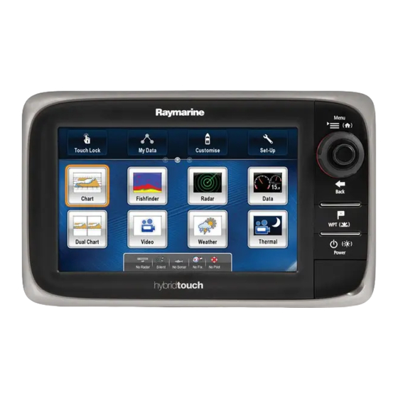
- Page 15 Series sand e Series display variants The following c Series and e Series multifunction display variants are available Non- sonar Sonar Series Controls Features • Bluetooth. e Series (E62354) (E62355) • Wi-Fi HybridTouch (Touchscreen and • NMEA 0183 physical buttons) •...
-
Page 16: Lighthouse Mfd Operation Instructions
In these situations, Raymarine strongly recommends that you activate the touch lock and use the physical buttons to operate your multifunction display. a Series / c Series / e Series installation instructions... -
Page 17: Chapter 3 Planning The Installation
3.9 a9x and a12x parts supplied on page 28 • 3.10 e7 / e7D Parts supplied on page 29 • 3.11 c Series and e Series parts supplied on page 29 • 3.12 Tools required for installation on page 30 •... -
Page 18: System Integration
• Apple iPhone or iPad • Android-compatible smartphone or tablet For media player control (Touchscreen MFDs only): • Any Bluetooth-enabled device that supports Bluetooth 2.1+ EDR power class 1.5 (supported profile: AVRCP 1.0) a Series / c Series / e Series installation instructions... - Page 19 • 1 x bait / fish. GNSS Receiver Any combination of the following: SeaTalk, SeaTalk ng® , or NMEA (external) — 0183 • RS130 GPS Raymarine ® • Raystar125 GPS • Raystar125+GPS (via optional ng® SeaTalk to SeaTalk converter) Instruments — As determined by SeaTalk ng®...
- Page 20 (VGA Style) e9x / e12x / e165 = 1 eS9x / eS12x = HDMI eS7x = 0 gS Series = HDMI eS9x / eS12x = 1 gS Series = 1 a Series / c Series / e Series installation instructions...
- Page 21 • Any 600 watt / 1Kw compatible transducer (via optional E66066 adaptor cable) ; OR: • Any Minn Kota transducer (via optional A62363 adaptor cable) Connection via external Raymarine ® Sonar Module: • Any sonar module-compatible transducer DownVision ™ Direct connection to internal...
- Page 22 • T200 Series SeaTalk (for control), BNC Raymarine ® connector (for video) • T300 Series • T400 Series • T800 Series • T900 Series Remote keypad Multiple • RMK-9 SeaTalk a Series / c Series / e Series installation instructions...
- Page 23 Fusion 700 series entertainment SeaTalk systems systems: • MS-IP700 • MS-AV700 PC / laptop Windows-compatible PC or laptop SeaTalk running Raymarine ® Voyage Planner software. Note: Raymarine ® cannot guarantee the compatibility of any third-party devices listed above. Planning the installation...
-
Page 24: Installation Checklist
MDS-compliant software is not available and you do NOT want the system to automatically attempt to resolve data conflicts, any non-compliant product(s) can be removed or replaced to ensure the entire system is MDS-compliant. a Series / c Series / e Series installation instructions... -
Page 25: Identifying Your Display Variant
. It is recommended that all networked displays contain the same software version. Software versions • All networked aa Series, c Series and e Series displays must contain LightHouse software release V4.32 or later. • All networked gS Series displays must contain LightHouse software release V7.43 or later. -
Page 26: System Protocols
Up to 50 units can simultaneously transmit and receive on a single physical bus at any one time, with each node being physically addressable. The standard was specifically intended to allow for a Series / c Series / e Series installation instructions... -
Page 27: Data Master
3.7 Data master a whole network of marine electronics from any manufacturer to communicate on a common bus via Any system containing more than one networked standardized message types and formats. multifunction display must have a designated data master. SeaTalk The data master is the display which serves as a SeaTalk is a protocol which enables compatible primary source of data for all displays, it also handles... -
Page 28: A6X And A7X Parts Supplied
1 m (3.3 ft.) SeaTalk ng® spur cable 2 m (6.6 ft.) RayNet cable 1.5 m (4.9 ft.) Power and data cable (Power/NMEA/Video) a Series / c Series / e Series installation instructions... -
Page 29: E7 / E7D Parts Supplied
3.11 c Series and e Series parts supplied The parts shown below are supplied with the e7 / e7D multifunction display. The parts shown below are supplied with the c Series and e Series(Excluding e7 and e7D) multifunction displays. D12170-4 1. Sun cover. D12248-2 2. -
Page 30: Tools Required For Installation
/ receivers. • Power supply Select a location that is as close as possible to the vessel’s DC power source. This will help to keep cable runs to a minimum. a Series / c Series / e Series installation instructions... - Page 31 250 mm (9.84 in.) issues related to the prevailing conditions. EMC installation guidelines GPS location requirements Raymarine equipment and accessories conform to In addition to general guidelines concerning the the appropriate Electromagnetic Compatibility (EMC) location of marine electronics, there are a number...
- Page 32 (5.9 in.) (5.9 in.) (5.9 in.) using internationally agreed standards and should be used for comparison purposes only. Do NOT install the product before testing its viewability in the desired location. a Series / c Series / e Series installation instructions...
- Page 33 Series and e Series product dimensions D12269-3 e125 / e127 e95 / e97 / e7 / e7D / c125 / e165 c95 / c97 c127 233 mm 289.6 mm 353.6 mm 426 mm (9.17 in.) (11.4 in.) (13.92 in.) (16.8 in.)
- Page 34 Series / c Series / e Series installation instructions...
-
Page 35: Chapter 4 Cables And Connections
4.23 Fusion network connection on page 56 • 4.24 Fusion NMEA 2000 connection on page 56 • 4.25 Media player connection on page 57 • 4.26 Raymarine mobile app connection on page 57 • 4.27 Bluetooth remote control connection on page 58 Cables and connections... -
Page 36: General Cabling Guidance
Coil any extra cable and tie it out of the way. • Where a cable passes through an exposed bulkhead or deckhead, use a suitable watertight feed-through. • Do NOT run cables near to engines or fluorescent lights. a Series / c Series / e Series installation instructions... -
Page 37: Connections Overview
4.2 Connections overview Details of the connections available on Raymarine multifunction displays are shown below. a65 / a75 a67 / a68 / a7 7 / a78 e95 / e125 / e165 e97 / e127 c95 / c125 c97 / c127... -
Page 38: A9X And A12X Connections Overview
• Your product’s power cable may have a fitted in-line fuse, if not then you must add an in-line fuse / breaker to the positive wire of your products power connection. a Series / c Series / e Series installation instructions... -
Page 39: Power And Data (Combined) Connection
NOT cover every scenario. If you are unsure how to provide the correct level of protection, 6. Black cable (negative) please consult an authorized Raymarine dealer or 7. Video input cable a suitably qualified professional marine electrician. 8. NMEA 0183 data cables Implementation —... - Page 40 Before applying power to this product, for the thermal breaker or fuse is dependent on the ensure it has been correctly grounded, in number of devices you are connecting. accordance with the instructions provided. a Series / c Series / e Series installation instructions...
-
Page 41: Seatalk Ng® Connections
Chapter 10 Spares and accessories. SeaTalk power requirements The SeaTalk bus requires a 12 V power supply. Power may be provided from: • Raymarine equipment with a regulated 12 V power supply (for example, a SmartPilot SPX course computer); or: Cables and connections... -
Page 42: Nmea 2000 Connection
DeviceNet adaptor cable Connecting the display to an existing NMEA 2000 (DeviceNet) backbone D12175-3 1. MFD 2. SeaTalk ng® to DeviceNet adaptor cable 3. DeviceNet backbone 4. NMEA 2000 equipment a Series / c Series / e Series installation instructions... -
Page 43: Seatalk Connection
4.8 SeaTalk connection 4.9 NMEA 0183 connection — Power/NMEA/Video cable You can connect SeaTalk devices to your MFD using the optional SeaTalk to SeaTalk ng® converter. NMEA 0183 devices can be connected directly to MFDs with a combined Power/NMEAVideo cable. Refer to the Connection Overview section to establish the NMEA 0183 connection method for your MFD. -
Page 44: A6X And A7X To Nmea 0183 Dsc Vhf Radio Connection
NMEA 0183 connection (use cable supplied with VHF radio) Note: The connection at the VHF radio must be to the NMEA 0183 input only. It is a uni-directional (one-way) connection. a Series / c Series / e Series installation instructions... -
Page 45: Sonar Module And Transducer Connection
10.3 Digital ClearPulse Transducers and the display’s network connection or can be connected accessories for a list of transducer that can be to the SeaTalk network, via a Raymarine ® network connected directly to 600 W internal sonar variant switch. -
Page 46: Radar Network Connection
This does NOT apply to any systems that do NOT include a CP300 or CP450C sonar module. Note: For software downloads and instructions on how to update the software for your product(s), D12253-3 visit www.raymarine.com/software. 1. Radar scanner a Series / c Series / e Series installation instructions... - Page 47 For longer cable runs a Radar power and data digital cable extension is required. D12254-1 1. Radar extension cable. 2. Radar power and data digital cable. 3. Raymarine ® network switch (or crossover coupler if connecting Radar directly to display). 4. RayNet cable (or RayNet to SeaTalk cable, if connecting via a crossover coupler) Note: The power connection is NOT shown in the diagram.
- Page 48 RayNet 25 m (82.0 ft) Power and data digital cable Note: The maximum length for the radar power and data digital cable (including any extensions) is 25 m (82 ft). a Series / c Series / e Series installation instructions...
-
Page 49: Ga150 Connection
4.13 GA150 connection 4.14 GNSS / GPS connection If your MFD has a GA150 connection, the external Depending on display variant, your multifunction antenna can be connected to help improve the display may include an internal GNSS or GPS GNSS (GPS / GLONASS) receiver’s reception. receiver. -
Page 50: Ais Connection
An AIS unit can be connected to the MFD by following the details provided in section 4.9 NMEA 0183 connection — Power/NMEA/Video cable the installation instructions provided with the unit. a Series / c Series / e Series installation instructions... -
Page 51: Keypad Network Connection
For information on connecting an SR50 using D12694-3 SeaTalk please refer to 82257 – SR50 operation 1. MFD which can be downloaded from the Raymarine website: www.raymarine.com. 2. Network connection to MFD or Raymarine ® network switch (RayNet cable) For further information regarding weather receiver installation (including power connection and 3. -
Page 52: Video Connection - Composite
Video out Examples of video output devices that you can connect to the display include: • HDTV with VGA input • VGA monitor a Series / c Series / e Series installation instructions... -
Page 53: Ip Camera Connection
SeaTalk network, via a Raymarine ® network switch. The network connection transmits the video signal to a compatible Raymarine ® MFD. IP camera direct connection D12329-2 1. MFD D12592-5 2. -
Page 54: Thermal Camera Connection
T300 / T400 Series connection. SeaT alk / RayNet SeaT alk / RayNet SeaT alk / RayNet D12260-2 1. MFD 2. Video connection to MFD (composite video) 3. Network connection to MFD (RayNet cable) a Series / c Series / e Series installation instructions... - Page 55 4. Raymarine ® network switch Raymarine recommends the use of a BNC terminated RG59 75ohm (or better) coaxial cable. 5. Video cable 6. RayNet to RJ45 SeaTalk adaptor cables 7. PoE (Power over Ethernet) injector (only required if using the optional JCU) 8.
-
Page 56: Fusion Network Connection
The table below details the Fusion entertainment systems that are compatible with Raymarine ® LightHouse powered MFDs. NMEA 2000 SeaTalk Fusion unit connection connection 650 Series 700 Series 750 Series RA205 Series a Series / c Series / e Series installation instructions... -
Page 57: Media Player Connection
The media player must be compatible with the Bluetooth 2.1+ EDR power class 1.5 (supported Raymarine apps allow you to stream and / or control, profile: AVRCP 1.0) or higher. remotely what you see on your multifunction display to a compatible device, using a Wi-Fi connection. -
Page 58: Bluetooth Remote Control Connection
RCU-3) To use the remote control you must first: • Enable Bluetooth in the System Settings on the multifunction display • Pair the remote control unit with the multifunction display a Series / c Series / e Series installation instructions... -
Page 59: Chapter 5 Mounting
Chapter 5: Mounting Chapter contents • 5.1 Mounting - a Series on page 60 • 5.2 Mounting - c Series and e Series on page 62 Mounting... -
Page 60: Mounting - A Series
1. Carefully lift one edge of the screen protection 9. Connect the power, data and other cables to the film, so that it is accessible for removing when unit. unit installation is complete. a Series / c Series / e Series installation instructions... - Page 61 2. Ensure the memory card slot door is in the open Important: Use care when removing the bezel. position. Do not use any tools to lever the bezel; doing so 3. Orientate the bottom-right side of the bezel under may cause damage. the lip of the chart card door and place the bezel 1.
-
Page 62: Mounting - C Series And E Series
2. Place the bezel over the rear of the display, ensuring that it is correctly aligned with the display. Apply firm but even pressure to the bezel along the: a Series / c Series / e Series installation instructions... - Page 63 i. Outer edges - work from the sides upwards and then along the top edge, to ensure that it clips securely into position. ii. Inner edges - ensure that the bezel sits flat against the unit. D12183-3 3. Use the supplied screws to secure the bezel to the display (e7 and e7D only).
- Page 64 Do not use any tools to lever the bezel; doing so may cause damage. 1. Place both your thumbs on the upper left edge of the display, at the positions indicated in the diagram above. a Series / c Series / e Series installation instructions...
-
Page 65: Chapter 6 Maintaining Your Display
Chapter 6: Maintaining your display Chapter contents • 6.1 Service and maintenance on page 66 • 6.2 Product cleaning on page 66 Maintaining your display... -
Page 66: Service And Maintenance
1. Carefully remove the sun cover from the display. 2. Rinse the sun cover with fresh water to remove all dirt particles and salt deposits. 3. Allow the sun cover to dry naturally. a Series / c Series / e Series installation instructions... -
Page 67: Chapter 7 Troubleshooting
Chapter 7: Troubleshooting Chapter contents • 7.1 Troubleshooting on page 68 • 7.2 Power up troubleshooting on page 69 • 7.3 Radar troubleshooting on page 70 • 7.4 GPS troubleshooting on page 71 • 7.5 Sonar troubleshooting on page 72 •... -
Page 68: Troubleshooting
If after referring to this section you are still having problems with your unit, please contact Raymarine Technical Support for further advice. a Series / c Series / e Series installation instructions... -
Page 69: Power Up Troubleshooting
Software corruption In the unlikely event that the products software has become corrupted please try re-flashing the latest software from the Raymarine website. On display products, as a last resort, you can try to perform a ‘Power on Reset’, however this will delete all settings/presets and user data (such as waypoints and tracks) and revert the unit back to factory defaults. -
Page 70: Radar Troubleshooting
24 V, Voltage at output = 40 V) “sleep mode” The bearing of a target on the The radar bearing alignment Check and adjust radar bearing alignment. radar screen is incorrect. requires correcting. a Series / c Series / e Series installation instructions... -
Page 71: Gps Troubleshooting
7.4 GPS troubleshooting Problems with the GPS and their possible causes and solutions are described here. Problem Possible causes Possible solutions “No Fix” GPS status icon is Geographic location or prevailing Check periodically to see if a fix is obtained in better displayed. -
Page 72: Sonar Troubleshooting
/ RayNet network problem. • Check that the unit is correctly connected to the multifunction display or Raymarine network switch. If a crossover coupler or other coupler cable / adapter is used, check all connections ensuring connections are secure, clean and free from corrosion, replace if necessary. - Page 73 Possible causes Possible solutions With the product under load, using a multi-meter, check for high voltage drop across all connectors/fuses etc (this can cause the Fishfinder applications to stop scrolling or the unit to reset/turn off), replace if necessary. Vessel speed too high Slow vessel speed and recheck.
- Page 74 Transducer does not have a speed element Install transducer with speed element to enable speed readings. Incorrect transducer selected (no speed Select a transducer that supports speed measurement from the Transducer displayed) Set-Up menu. a Series / c Series / e Series installation instructions...
-
Page 75: Sonar Crosstalk Interference
• Adjust the Interference Rejection Filter. The you may experience some operating in overlapping default setting for all Raymarine MFDs is “Auto”. minor crosstalk interference frequency ranges, you may Changing this setting to “High” might help to... - Page 76 Being able to easily identify the way in which interference is displayed in the Fishfinder application can sometimes be the best and easiest route to dealing with it. a Series / c Series / e Series installation instructions...
-
Page 77: Thermal Camera Troubleshooting
VIS / IR switching. image . VIS / IR cable not connected. Ensure that the VIS / IR cable is connected from the camera to the Raymarine system. (The IR-only cable does not support switching). Noisy image. Poor quality or faulty video Ensure that the video cable is no longer than necessary. - Page 78 Image is inverted (upside down). Camera “Ball down” setting is Ensure that the Ball down setting within the thermal incorrect. camera system setup menu is set correctly. a Series / c Series / e Series installation instructions...
-
Page 79: System Data Troubleshooting
Network problem. Check that all required equipment is connected to the is missing from some but not all network. displays. Check the status of the Raymarine network Switch. Check that SeaTalk / RayNet cables are free from damage. Software mismatch between Contact Raymarine technical support. -
Page 80: Video Troubleshooting
Problems with the video inputs and their possible causes and solutions are described here. Problem Possible causes Possible solutions No signal message on screen Cable or connection fault Check that the connections are sound and free from (video image not displayed) corrosion. a Series / c Series / e Series installation instructions... -
Page 81: Wi-Fi Troubleshooting
Device (available from the phone's Settings menu). the multifunction display. Ensure that the Raymarine connection is selected as the Wi-Fi network. If a passcode has been specified for the multifunction display's Wi-Fi connection ensure that the same passcode is entered into the Smart Device when prompted. -
Page 82: Bluetooth Troubleshooting
Temporarily disable each wireless device in turn until you have identified the device causing the interference. a Series / c Series / e Series installation instructions... -
Page 83: Touchscreen Troubleshooting
7.12 Touchscreen troubleshooting Problems with the touchscreen and their possible causes and solutions are described here. Problem Possible causes Possible solutions Touchscreen does not operate Touch lock is enabled. Use the Joystick to turn off the touch lock on the home as expected. -
Page 84: Touchscreen Alignment
“Incorrect touch detected" message is displayed, the alignment exercise is repeated. 9. After 2 failed alignment exercises you may be asked to perform a precision alignment exercise. a Series / c Series / e Series installation instructions... -
Page 85: Miscellaneous Troubleshooting
Check that the power source is of the correct voltage and erratic behavior. sufficient current. Software mismatch on system Go to www.raymarine.com and click on support for the (upgrade required). latest software downloads. Corrupt data / other unknown Perform a factory reset. - Page 86 Series / c Series / e Series installation instructions...
-
Page 87: Chapter 8 Technical Specification
Chapter 8: Technical specification Chapter contents • 8.1 a Series on page 88 • 8.2 c and e Series on page 92 Technical specification... -
Page 88: Series
CPT-100 transducer. LEN (Refer to Seatalk reference manual for further information). a7x Power specification Nominal supply voltage 12 V dc Operating voltage range 10.8 V dc to 15.6 V dc a Series / c Series / e Series installation instructions... - Page 89 If Power consumption Full brightness: in doubt consult an authorized Raymarine dealer • a125 — 23 W Max Power consumption Full brightness: • a127 — 23.9 W Max • a75 — 7.7 W Max •...
- Page 90 Mbits/s • Beidou B1 GA150 1 x TNC type external GPS / GLONASS Signal Acquisition Automatic antenna connection Almanac Update Automatic Video input 1 x BNC type video input connection a Series / c Series / e Series installation instructions...
- Page 91 GNSS when it becomes available. A GA150 must be connected to receive Beidou. Please eS Series 6 GB 266.6 minutes check with your Raymarine dealer for further details. Note: • The available internal storage stated above is Internal 600 W sonar specification based on MFD manufactured after May 2014.
-
Page 92: C And E Series
• 2.165 kg (4.77 lb.) e97 / c97 • 2.265 kg (4.99 lb.) Weight (boxed unit) e95 / c95 • 3.540 kg (7.8 lb.) e97 / c97 • 3.635 kg (8 lb.) a Series / c Series / e Series installation instructions... - Page 93 e125 / e127 / c125 / c127 Physical Power consumption Full brightness: specifications • e7 — 10 W Dimensions • Width: 354 mm (13.94 in.) • e7D — 13.8 W • Height (NOT including PowerSave mode: bracket): 222 mm (8.74 in.) •...
- Page 94 / e97 / c95 / c97 Display specification information). Size 9 in. Type TFT backlit LED Color depth 24–bit Resolution 800 x 480 pixels (WVGA) Maximum allowable wrongly illuminated pixels a Series / c Series / e Series installation instructions...
- Page 95 Transmit power Up to 600 W RMS, depending pixels on transducer Depth range Up to 3000 ft, depending on c Series and e Series data connections transducer Wired connections Video specification NMEA 0183 2x NMEA 0183 ports: Signal type Composite •...
- Page 96 • NMEA 2000 certification • WiFi Alliance certification • Bluetooth certification • Europe: 1999/5/EC • Australia and New Zealand: C-Tick, Compliance Level 2 • FCC 47CFR part 15 • Industry Canada RSS210 a Series / c Series / e Series installation instructions...
-
Page 97: Chapter 9 Technical Support
Chapter 9: Technical support Chapter contents • 9.1 Raymarine product support and servicing on page 98 • 9.2 Learning resources on page 99 • 9.3 Third-party support on page 99 Technical support... -
Page 98: Raymarine Product Support And Servicing
Telephone and e-mail support Region Tele- E-mail phone United Kingdom support.uk@raymarine.com (UK), EMEA, (0)1329 and Asia Pacific 246 777 United States +1 (603) support@raymarine.com (US) 324 7900 (Toll-free: +800 539 5539) a Series / c Series / e Series installation instructions... -
Page 99: Learning Resources
Internet connection. • Some videos are only available in English. Training courses Raymarine regularly runs a range of in-depth training courses to help you make the most of your products. Visit the Training section of the Raymarine website for more information: •... - Page 100 Series / c Series / e Series installation instructions...
-
Page 101: Chapter 10 Spares And Accessories
Chapter 10: Spares and accessories Chapter contents • 10.1 a Series spares on page 102 • 10.2 c Series and e Series spares on page 102 • 10.3 Digital ClearPulse Transducers and accessories on page 103 • 10.4 DownVision transducers and accessories on page 104 •... -
Page 102: Series Spares
1.5 m (4.9 ft) Mounting R70008 R70009 adaptor kit (Wid- escreen MFDs) Mounting R70010 R70011 adaptor (Classic MFDs) Mounting R62369 screw kit Flush R62376 R70079 R70080 R70125 mount panel kit a Series / c Series / e Series installation instructions... -
Page 103: Digital Clearpulse Transducers And Accessories
10.3 Digital ClearPulse Transducers e9 and e12 Video cables and accessories The following video cable is required for the video in / out connector on the e95 / e97 / e125 / e127 variant The transducers listed below can be connected multifunction displays. -
Page 104: Tm Transducers And
0.5 m (1.64 ft) 600 watt sonar transducer adaptor module-compatible cable for DSM transducers sonar transducer directly to a sonar variant multifunction display. E66074 3 m (9.84 ft.) transducer extension cable a Series / c Series / e Series installation instructions... -
Page 105: Network Hardware
10.5 Network hardware Part num- Item Notes HS5 RayNet A80007 5–port switch for network network switch connection of multiple devices featuring RayNet connectors. Equipment with RJ45 SeaTalk connectors can also be connected using suitable adapter cables. RJ45 SeaTalk E55058 8–port switch for network network switch connection of multiple SeaTalk... -
Page 106: Raynet To Raynet Cables And Connectors
RayNet (male) plug at the other end. Adapter cable with a RayNet (male) Suitable for joining (female) RayNet cables together for plug on both ends. longer cable runs. a Series / c Series / e Series installation instructions... - Page 107 • E55051 (10 m). • A62135 (15 m). • E55052 (20 m). Adapter cable with a RayNet (female) Directly connect a Raymarine radar scanner with an RJ45 socket on one end, and a waterproof SeaTalk (male) cable to a RayNet network switch (e.g.
-
Page 108: Network Cable Connector Types
SeaTalk devices to the multifunction display via RayNet cables. Also required for connecting a crossover coupler if only one device is being connected to the display's Network connector. a Series / c Series / e Series installation instructions... -
Page 109: Network Cable Types
Spurs from the backbone are lengths) used to connect SeaTalk – Thermal camera via PoE injector. devices. – Additional Raymarine network switch. T-piece connector Used to make junctions in the – PC or laptop using Voyage Planner software. backbone to which devices can then be connected. - Page 110 Connects an SPX course SeaTalk spur computer or an ACU to a cable 0.3 m (1.0 ft) SeaTalk backbone. A06047 SeaTalk (3 pin) to SeaTalk adaptor cable 0.4 m (1.3 ft) a Series / c Series / e Series installation instructions...
- Page 112 Raymarine UK Limited, Marine House, Cartwright Drive, Fareham, PO15 5RJ. United Kingdom. Tel: +44 (0)1329 246 700...
Need help?
Do you have a question about the E SERIES and is the answer not in the manual?
Questions and answers