Table of Contents
Advertisement
Quick Links
Advertisement
Chapters
Table of Contents

Subscribe to Our Youtube Channel
Related Manuals for IEI Technology EP-265-GM45


Summary of Contents for IEI Technology EP-265-GM45
- Page 1 EP-265-GM45/EP-267-GM45 Enrich POS System EP-265-GM45/EP-267-GM45 Enrich POS System MODEL: EP-265-GM45/EP-267-GM45 Fanless Intel® Celeron® M Enrich POS System with Touch Screen, 1 GB DDR2, PoweredUSB, VGA, 5 V/12 V Serial Ports and AT/ATX Power Support User Manual Page i Rev. 1.00 19 February, 2009...
- Page 2 E-265-GM45/EP-267-GM45 Enrich POS System Revision Date Version Changes 19 February, 2009 1.00 Initial release Page ii...
- Page 3 EP-265-GM45/EP-267-GM45 Enrich POS System Copyright COPYRIGHT NOTICE The information in this document is subject to change without prior notice in order to improve reliability, design and function and does not represent a commitment on the part of the manufacturer. In no event will the manufacturer be liable for direct, indirect, special, incidental, or consequential damages arising out of the use or inability to use the product or documentation, even if advised of the possibility of such damages.
-
Page 4: Packing List
EP series from or contact an IEI sales representative directly. To contact an IEI sales representative, please send an email to sales@iei.com.tw. The items listed below should all be included in the EP-265-GM45/EP-267-GM45 series package. 1 x EP-265-GM45/EP-267-GM45 POS system... -
Page 5: Table Of Contents
EP-265-GM45/EP-267-GM45 Enrich POS System Table of Contents INTRODUCTION..................... 1 1.1 EP-265-GM45/EP-267-GM45 E POS O ........... 2 NRICH VERVIEW 1.1.1 Features and Model Variations................3 1.1.2 Applications ....................... 3 1.2 E ....................4 XTERNAL VERVIEW 1.2.1 General Description................... 4 1.2.2 Monitor Front Panel ..................4 1.2.3 Monitor Right Side Panel................... - Page 6 E-265-GM45/EP-267-GM45 Enrich POS System 2.4.4 Keyboard and Mouse Connectivity ..............20 2.5 EP-265-GM45/EP-267-GM45 F ............21 RONT 2.5.1 Monitor ......................21 2.5.2 Touch-Screen Module..................21 2.6 G ........................ 21 RAPHICS ® 2.6.1 Intel GM45 Integrated Gen 5.0 Graphics Engine ......... 21 2.6.2 Dual-Display....................
- Page 7 EP-265-GM45/EP-267-GM45 Enrich POS System 4.8.1 Access the Jumpers ..................38 4.8.2 Preconfigured Jumpers ..................40 4.8.3 Cash Drawer Voltage Select ................40 4.8.4 CF Voltage Select ..................... 41 4.8.5 Clear CMOS Jumper..................42 4.8.6 COM3, COM4 and COM5 Pin 9 Select............43 4.9 M...
- Page 8 E-265-GM45/EP-267-GM45 Enrich POS System 6.3.2 IDE Configuration ................... 64 6.3.2.1 IDE Master, IDE Slave ................66 6.3.3 Super IO Configuration ................... 71 6.3.4 Hardware Health Configuration..............76 6.3.5 AHCI Configuration..................80 6.3.5.1 AHCI Port n ....................81 6.3.6 Remote Configuration ..................82 6.3.7 USB Configuration...................
- Page 9 EP-265-GM45/EP-267-GM45 Enrich POS System B.4 VGA C ....................112 ONNECTOR SAFETY PRECAUTIONS..................113 C.1 S ....................114 AFETY RECAUTIONS C.1.1 General Safety Precautions................114 C.1.2 Anti-static Precautions ...................115 C.2 M ............115 AINTENANCE AND LEANING RECAUTIONS C.2.1 Maintenance and Cleaning ................115 C.2.2 Cleaning Tools....................116 BIOS CONFIGURATION OPTIONS ..............117 D.1 BIOS C...
- Page 10 Figure 1-2: EP-265-GM45/EP-267-GM45 Monitor Front View ........4 Figure 1-3: EP-265-GM45/EP-267-GM45 Viewing Angle Adjustment .......5 Figure 1-4: EP-265-GM45/EP-267-GM45 Monitor Right Side View ......5 Figure 1-5: I/O Interface Connectors on the Monitor Right Side Panel ....6 Figure 1-6: EP-265-GM45/EP-267-GM45 I/O Interface Panel ........7 Figure 1-7: EP-265-GM45/EP-267-GM45 Left Side View ..........8...
- Page 11 EP-265-GM45/EP-267-GM45 Enrich POS System Figure 4-3: CF Card Installation.................35 Figure 4-4: HDD Bracket Retention Screws .............36 Figure 4-5: Secure the HDD with the HDD Bracket..........36 Figure 4-6: HDD Installation ..................37 Figure 4-7: Jumper Locations..................37 Figure 4-8: Bottom Panel Retention Screws ............39 Figure 4-9: Motherboard Chassis Retention Screws..........39...
- Page 12 E-265-GM45/EP-267-GM45 Enrich POS System List of Tables Table 1-1: EP-265-GM45/EP-267-GM45 System Specifications......11 Table 4-1: Jumpers......................38 Table 4-2: Preconfigured Jumpers ................40 Table 4-3: Cash Drawer Voltage Select Jumper Settings ........40 Table 4-4: CF Voltage Select Jumper Settings............41 Table 4-5: Clear CMOS Jumper Settings ..............43 Table 4-6: COM2, COM3 and COM5 Pin 9 Setting Jumper Settings ......44...
-
Page 13: Introduction
EP-265-GM45/EP-267-GM45 Enrich POS System Chapter Introduction Page 1... -
Page 14: Ep-265-Gm45/Ep-267-Gm45 Enrich Pos Overview
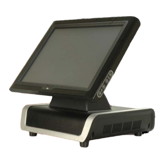
1.1 EP-265-GM45/EP-267-GM45 Enrich POS Overview Figure 1-1: EP-265-GM45/EP-267-GM45 Enrich POS The EP-265-GM45 and EP-267-GM45 are Intel® Celeron® M powered POS systems with a rich variety of functions and peripherals. Both EP-265-GM45 and EP-267-GM45 are designed for easy and simplified integration in to point-of-sales (POS) applications. -
Page 15: Features And Model Variations
EP-265-GM45/EP-267-GM45 Enrich POS System 1.1.1 Features and Model Variations There are two models in the EP GM45 series, the EP-265-GM45 and the EP-267-GM45. Both models feature the following: Mobile 2.0 GHz Intel® Celeron® M processor Intel® GM45 chipset 1 GB DDR2 SDRAM preinstalled 802.11 b/g PCIe wireless module with PIFA antennas... -
Page 16: External Overview
1.2.2 Monitor Front Panel The front side of the EP-265-GM45/EP-267-GM45 is a flat panel TFT LCD screen surrounded by an ABS/PC plastic hard cover (Figure 1-2). The front panel can be tilted to adjust the viewing angle (Figure 1-3). -
Page 17: Monitor Right Side Panel
Figure 1-3: EP-265-GM45/EP-267-GM45 Viewing Angle Adjustment 1.2.3 Monitor Right Side Panel The right side panel of the EP-265-GM45/EP-267-GM45 monitor has a set of buttons to control the LCD brightness and the volume of the speakers. The monitor right side panel also provides access to the I/O interface panel that enables connection to a wide range of external peripheral devices (Figure 1-4). -
Page 18: I/O Interface Panel
Figure 1-5: I/O Interface Connectors on the Monitor Right Side Panel 1.2.4 I/O Interface Panel The I/O interface panel is located on the rear side of the EP-265-GM45/EP-267-GM45 chassis and protected by an easily-removed cover (Figure 1-6). The I/O interface panel... -
Page 19: Figure 1-6: Ep-265-Gm45/Ep-267-Gm45 I/O Interface Panel
3 x 5 V / 12 V serial port connectors (COM3, COM4 and COM5) 1 x VGA connector The external I/O interface connectors on the rear panel are shown in Figure 1-6. Figure 1-6: EP-265-GM45/EP-267-GM45 I/O Interface Panel Page 7... -
Page 20: Chassis Left Side Panel
E-265-GM45/EP-267-GM45 Enrich POS System 1.2.5 Chassis Left Side Panel The left side panel of the chassis has a power switch to control the system ATX power on/off (Figure 1-7). Figure 1-7: EP-265-GM45/EP-267-GM45 Left Side View 1.3 Specifications 1.3.1 Preinstalled Hardware Components EP-265-GM45/EP-267-GM45... -
Page 21: System Specifications
EP-265-GM45/EP-267-GM45 Enrich POS System The following section lists the system specifications. The technical specifications for some other preinstalled components are shown in the Appendix A. 1.3.2 System Specifications The technical specifications for the EP-265-GM45/EP-267-GM45 system are listed in Table 1-1. Specification EP-265-GM45... - Page 22 E-265-GM45/EP-267-GM45 Enrich POS System Expansion 1 x PCIe Mini interface (wireless LAN 802.11 b/g module) HDD Drive Bay 2 x 2.5” SATA HDD bays Construction Material ABS + PC plastic front frame Aluminum alloy chassis Front Panel Color Black Operation Temperature 0ºC ~ 40ºC Dimensions (W x H x D) (mm) 375.00 x 392.66 x 334.64 406.00 x 414.52 x 350.47...
-
Page 23: Table 1-1: Ep-265-Gm45/Ep-267-Gm45 System Specifications
1 x VGA connector I/O Ports and Switches 1 x Serial port connector (COM1) (Monitor Rear Panel) 1 x 12 V PoweredUSB connector 2 x USB 2.0 connectors 1 x COM1 power selecting switch Table 1-1: EP-265-GM45/EP-267-GM45 System Specifications Page 11... -
Page 24: Detailed Specifications
E-265-GM45/EP-267-GM45 Enrich POS System Chapter Detailed Specifications Page 12... -
Page 25: Dimensions
EP-265-GM45/EP-267-GM45 Enrich POS System 2.1 Dimensions The following sections provide detailed schematics and information on the dimensions of the EP-265-GM45/EP-267-GM45. 2.1.1 EP-265-GM45 Dimensions The dimensions of the EP-265-GM45 are shown in Figure 2-1 and listed below. 375.00 mm Width: 392.66 mm Height: 334.64 mm... -
Page 26: Ep-267-Gm45 Dimensions
E-265-GM45/EP-267-GM45 Enrich POS System 2.1.2 EP-267-GM45 Dimensions The dimensions of the EP-267-GM45 are shown in Figure 2-1 and listed below. 406.00 mm Width: 414.52 mm Height: 350.47 mm Depth: Figure 2-2: EP-267-GM45 Dimensions (mm) ® ® 2.2 Intel Celeron M Processor Support A 2.0 GHz Intel®... -
Page 27: Motherboard Components
The following sections describe some of the features on the motherboard. 2.3.1 Memory Support 2.3.1.1 Installed Memory One 240-pin 1.0 GB DDR2 SDRAM DIMM is installed in the EP-265-GM45/EP-267-GM45 and controlled by the Intel® GM45 GMCH installed on the internal motherboard. 2.3.1.2 Additional Memory The Intel®... -
Page 28: Storage Capacity
E-265-GM45/EP-267-GM45 Enrich POS System Figure 2-4: Memory Module and Memory Socket 2.3.2 Storage Capacity The EP-265-GM45/EP-267-GM45 comes with two hard disk drive bays for two 2.5” SATA HDDs (Figure 2-5). The hard disk drive bay can be access by removing the bottom panels. -
Page 29: External Peripheral Interface Connectors
POS system. 2.4.1 Serial Port Connectors The EP-265-GM45/EP-267-GM45 has four serial ports, one on the monitor rear panel (COM1) and three on the I/O interface panel (COM3, COM4 and COM5). Pin 9 on these four serial port DB-9 connectors can be set as either +5 V or +12 V. -
Page 30: Lan Connectivity
E-265-GM45/EP-267-GM45 Enrich POS System Figure 2-7: COM Ports and LED Indicators Two of the serial ports (COM1 and COM2) are interfaced to the ITE IT8712 super I/O, through the low pin count (LPC) bus to the ICH9M Southbridge. The remaining four serial ports (COM3, COM4 and COM5) are connected to the ICH9M LPC bus through a Fintek serial port controller. -
Page 31: External Usb Connectors
2.4.3 External USB Connectors 2.4.3.1 Standard USB Connectors The EP-265-GM45/EP-267-GM45 has four USB 2.0 connectors, two on the monitor rear panel and two on the chassis rear panel. All of the USB 2.0 connectors are interfaced directly to the USB controllers on the ICH9M Southbridge. The USB connectors are fully compliant with USB specification Revision 2.0 and USB specification Revision 1.1 and can... -
Page 32: Poweredusb Connectors
E-265-GM45/EP-267-GM45 Enrich POS System 2.4.3.2 PoweredUSB Connectors The EP-265-GM45/EP-267-GM45 has three PoweredUSB connectors, one on the monitor rear panel and two on the chassis rear panel. Two of these PoweredUSB connectors provide +12 V power to the peripheral devices. The remaining one PoweredUSB provides +24 V power for higher-power devices. -
Page 33: Ep-265-Gm45/Ep-267-Gm45 Front Side
EP-265-GM45/EP-267-GM45 Enrich POS System 2.5 EP-265-GM45/EP-267-GM45 Front Side 2.5.1 Monitor A 15” or 17” LCD screen is installed in the monitor of the EP POS system. The viewing angle of the IP 64 compliant front panel is adjustable. The screen is shown in Figure 2-12 below. -
Page 34: Dual-Display
The Integrated audio controller on the Intel® ICH9M Southbridge is integrated to a RealTek ALC883 audio codec. The RealTek ALC883 is a 7.1 channel High Definition Audio codec. 2.7.2 Stereo Speakers The EP-265-GM45/EP-267-GM45 has two built-in 3 W stereo speakers on the rear of the monitor (Figure 2-14). Page 22... -
Page 35: System Power
POS systems from a central management center. 2.8.1.2 ATX Power Mode With the ATX mode selected, the EP-265-GM45/EP-267-GM45 POS system goes in a standby mode when it is turned off. The POS system can be easily turned on via network or a power switch in standby mode. -
Page 36: Power Supply
Figure 2-15: Power Supply Unit 2.8.3 Power Connectors There are two power connectors on the EP-265-GM45/EP-267-GM45 POS system located on the chassis rear panel. One is a 12 V or 24 V input connector and the other is a 12 V output connector. These connectors are shown in Figure 2-16 below. -
Page 37: Power Input Connector
Figure 2-17: RJ-12 Connectors 2.9 Wireless Ethernet An integrate wireless LAN module and PIFA antenna on the EP-265-GM45/EP-267-GM45 ensures an uninterrupted wireless connection. PIFA antennas can receive high-quality, uniform signals in any location from all directions without any signal degradation or impedance and are the most efficient antennas on the market. -
Page 38: Thermal Management
POS system. The EP-265-GM45/EP-267-GM45 POS System is an effective heat dissipation system. The heat sink on the main board works together with the heat pipe to dissipate the heat from the POS system. -
Page 39: Unpacking
EP-265-GM45/EP-267-GM45 Enrich POS System Chapter Unpacking Page 27... -
Page 40: Unpacking
E-265-GM45/EP-267-GM45 Enrich POS System 3.1 Unpacking To unpack the flat POS system, follow the steps below: WARNING! The front side LCD screen has a protective plastic cover stuck to the screen. Only remove the plastic cover after the POS system has been properly installed. -
Page 41: Packing List
EP-265-GM45/EP-267-GM45 Enrich POS System 3.1.1 Packing List The EP-265-GM45/EP-267-GM45 POS system is shipped with the following components: Quantity Item Image EP-265-GM45/EP-267-GM45 POS system Screw set Power supply Power cord Touch pen User manual CD and driver CD If any of these items are missing or damaged, contact the distributor or sales representative immediately. -
Page 42: Installation
E-265-GM45/EP-267-GM45 Enrich POS System Chapter Installation Page 30... -
Page 43: Anti-Static Precautions
Electrostatic discharge (ESD) can cause serious damage to electronic components, including the EP-265-GM45/EP-267-GM45. Dry climates are especially susceptible to ESD. It is therefore critical that whenever the EP-265-GM45/EP-267-GM45 is accessed internally, or any other electrical component is handled, the following anti-static precautions are strictly adhered to. -
Page 44: Preinstalled Components
E-265-GM45/EP-267-GM45 Enrich POS System Anti-static Discharge: If a user open the rear panel of the POS system, to configure the jumpers or plug in added peripheral devices, ground themselves first and wear and anti-static wristband. 4.3 Preinstalled Components The following components are all preinstalled. Motherboard TFT LCD screen 1.0 GB DDR2 memory module... -
Page 45: Remove The Bottom Panels
To access the CF slot and HDD slot, the bottom panels must be removed. To remove the bottom panels, please follow the steps below. Adjust the monitor (Figure 4-1) and turn the EP-265-GM45/EP-267-GM45 over Step 1: to put the monitor front panel on the table. -
Page 46: Cf Card Installation
E-265-GM45/EP-267-GM45 Enrich POS System Figure 4-2: Bottom Panel Retention Screws 4.6 CF Card Installation The EP series has one CF Type II slot. To install the CF card, follow the instructions below. Remove the bottom panels. Refer to Section 4.5. Step 1: Install the CF Card. -
Page 47: Hdd Installation
EP-265-GM45/EP-267-GM45 Enrich POS System Figure 4-3: CF Card Installation Reinstall the bottom panels. Make sure the bottom panels are properly Step 3: secured with the previously removed retention screws.Step 0: 4.7 HDD Installation The EP series has two HDD slots inside the bottom panel for two 2.5” SATA HDDs. To install the HDD, follow the instructions below. -
Page 48: Figure 4-4: Hdd Bracket Retention Screws
E-265-GM45/EP-267-GM45 Enrich POS System Figure 4-4: HDD Bracket Retention Screws Place one 2.5” SATA HDD onto the HDD bracket as shown in Figure 4-5. Step 4: Connect the HDD to the SATA cable connector. Secure the HDD. Align the four retention screw holes on the both side of the Step 5: HDD with the retention screw holes of the HDD bracket. -
Page 49: Jumper Settings
EP-265-GM45/EP-267-GM45 Enrich POS System previously removed retention screws to secure the HDD bracket to the chassis. See Figure 4-6. Figure 4-6: HDD Installation Reinstall the bottom panels. Make sure the bottom panels are properly Step 7: secured with the previously removed retention screws.Step 0:... -
Page 50: Access The Jumpers
Table 4-1: Jumpers 4.8.1 Access the Jumpers To access the jumpers, please follow the steps below. Adjust the monitor and turn the EP-265-GM45/EP-267-GM45 over to put the Step 1: monitor front panel on the table. Remove the bottom panels. Remove the five retention screws (Figure 4-9) -
Page 51: Figure 4-8: Bottom Panel Retention Screws
Remove the aluminum chassis. The motherboard is installed inside the Step 3: aluminum chassis. To access the motherboard, remove the four retention screws and gently lift the aluminum chassis off the EP-265-GM45/EP-267-GM45. Step 0: Figure 4-9: Motherboard Chassis Retention Screws... -
Page 52: Preconfigured Jumpers
4.8.2 Preconfigured Jumpers WARNING: Do not change the settings on the jumpers in described here. Doing so may disable or damage the system The following jumpers are preconfigured for the EP-265-GM45/EP-267-GM45. Users should NOT change these jumpers. Jumper Name Label... -
Page 53: Cf Voltage Select
EP-265-GM45/EP-267-GM45 Enrich POS System The Cash Drawer Voltage Select jumper locations are shown in Figure 4-10 below. Figure 4-10: Cash Drawer Voltage Select Jumper Locations 4.8.4 CF Voltage Select Jumper Label: 3-pin header Jumper Type: See Table 4-4 Jumper Settings:... -
Page 54: Clear Cmos Jumper
See Figure 4-12 Jumper Location: If the EP-265-GM45/EP-267-GM45 fails to boot due to improper BIOS settings, the clear CMOS jumper clears the CMOS data and resets the system BIOS information. To do this, use the jumper cap to close the pins for a few seconds then remove the jumper clip. -
Page 55: Com3, Com4 And Com5 Pin 9 Select
EP-265-GM45/EP-267-GM45 Enrich POS System Load Failsafe Defaults. After having done one of the above, save the changes and exit the CMOS Setup menu. The clear CMOS jumper settings are shown in Table 4-5. Clear CMOS Description Short 1-2 Keep CMOS Setup... -
Page 56: Mounting The Second Display (Optional)
Figure 4-13: COM3, COM4 and COM5 Pin 9 Setting Jumper Locations 4.9 Mounting the Second Display (Optional) To mount a second display onto the EP-265-GM45/EP-267-GM45, please follow the steps below. Remove the I/O interface cover on the chassis rear panel of the Step 1: EP-265-GM45/EP-267-GM45 (Figure 4-14). -
Page 57: Figure 4-14: I/O Interface Cover Removal
Figure 4-15: Mounting Hole Cover Removal Align the thee retention screw holes on the second display device with the Step 3: retention screw holes on the mounting hole. Insert the three retention screws to secure the second display to the EP-265-GM45/EP-267-GM45 (Figure 4-16). Page 45... -
Page 58: Figure 4-16: Second Display Installation
E-265-GM45/EP-267-GM45 Enrich POS System Figure 4-16: Second Display Installation Organize the second display cables and connect the connector to the Step 4: connectors on the I/O interface panel (Figure 4-17). Figure 4-17: Organized Second Display Cables Replace the I/O interface cover. Step 5: Step 0: Page 46... -
Page 59: Bottom Panel Switch And Connectors
Locate the RJ-45 connectors on the I/O interface panel of the Step 1: EP-265-GM45/EP-267-GM45 series. Align the connectors. Align the RJ-45 connector on the LAN cable with one of Step 2: the RJ-45 connectors on the I/O interface panel of the EP-265-GM45/EP-267-GM45 series. See Figure 4-19. Page 47... -
Page 60: Serial Device Connection
RJ-45 connector into the RJ-45 connector. Step 0: 4.10.3 Serial Device Connection The EP-265-GM45/EP-267-GM45 series has four male DB-9 connectors for serial devices to be connected. Follow the steps below to connect a serial device to the EP-265-GM45/EP-267-GM45 series POS system. -
Page 61: Usb Device Connection
4.10.4 USB Device Connection There are four external USB 2.0 connectors. All connectors are perpendicular to the EP-265-GM45/EP-267-GM45 series. To connect a USB 2.0 or USB 1.1 device, please follow the instructions below. Located the USB connectors. The locations of the USB connectors are shown Step 1: in Chapter 2. -
Page 62: Parallel Device Connection
Step 0: 4.10.5 Parallel Device Connection The EP-265-GM45/EP-267-GM45 has a single female DB-25 connector on the chassis rear panel for parallel devices. Follow the steps below to connect a parallel device to the EP-265-GM45/EP-267-GM45. Locate the DB-25 connector. The location of the DB-25 connector is shown in Step 1: Chapter 3. -
Page 63: Figure 4-22: Parallel Device Connector
EP-265-GM45/EP-267-GM45 Enrich POS System Figure 4-22: Parallel Device Connector Secure the connector. Secure the DB-25 connector to the external interface by Step 3: tightening the two retention screws on either side of the connector. Step 0: Page 51... -
Page 64: System Maintenance
E-265-GM45/EP-267-GM45 Enrich POS System Chapter System Maintenance Page 52... -
Page 65: System Maintenance Introduction
EP-265-GM45/EP-267-GM45 Enrich POS System 5.1 System Maintenance Introduction If the components of the EP-265-GM45/EP-267-GM45 series fail they must be replaced. Components that can be replaced include: CF module SATA HDD Wireless LAN module DIMM module Please contact the system reseller or vendor to purchase the replacement parts. Back... -
Page 66: Turn Off The Power
Follow the steps described in Section 4.7 to replace the HDD. Step 3: Step 0: 5.4.2 CF Card Replacement The EP-265-GM45/EP-267-GM45 has one CF Type II slot. To replace the CF card, follow the instructions below. Follow all anti-static procedures. See Section 5.2. Step 1: Turn off the power. -
Page 67: Dimm Module Replacement
EP-265-GM45/EP-267-GM45 Enrich POS System 5.4.3 DIMM Module Replacement WARNING: Using incorrectly specified DIMM may cause permanently damage the EP-265-GM45/EP-267-GM45. Please make sure the purchased DIMM complies with memory specifications EP-265-GM45/EP-267-GM45. To replace the DIMM module, please follow the steps below. -
Page 68: Wireless Module Replacement
E-265-GM45/EP-267-GM45 Enrich POS System Open the DIMM socket handles. The DIMM socket has two handles that Step 6: secure the DIMM into the socket. Before the DIMM can be inserted into the socket, the handles must be opened. See Figure 5-2. Figure 5-2: Installing a DIMM Align the DIMM with the socket. -
Page 69: Motherboard Replacement
EP-265-GM45/EP-267-GM45 Enrich POS System Locate the wireless module. The wireless module is located below the DIMM Step 4: sockets. See Figure 5-3. Figure 5-3: Wireless Module Location Open the Mini PCIe socket arm clips. The Mini PCIe socket has two clips that Step 5: secure the Mini PCIe wireless module into the socket. -
Page 70: Ami Bios Setup
E-265-GM45/EP-267-GM45 Enrich POS System Chapter AMI BIOS Setup Page 58... -
Page 71: Introduction
EP-265-GM45/EP-267-GM45 Enrich POS System 6.1 Introduction A licensed copy of AMI BIOS is preprogrammed into the ROM BIOS. The BIOS setup program allows users to modify the basic system configuration. This chapter describes how to access the BIOS setup program and the configuration options that may be changed. -
Page 72: Getting Help
E-265-GM45/EP-267-GM45 Enrich POS System F1 key General help, only for Status Page Setup Menu and Option Page Setup Menu F2 /F3 key Change color from total 16 colors. F2 to select color forward. F10 key Save all the CMOS changes, only for Main Menu Table 6-1: BIOS Navigation Keys 6.1.3 Getting Help When F1 is pressed a small help window describing the appropriate keys to use and the... -
Page 73: Main
EP-265-GM45/EP-267-GM45 Enrich POS System 6.2 Main The Main BIOS menu (BIOS Menu 1) appears when the BIOS Setup program is entered. The Main menu gives an overview of the basic system information. BIOS Menu 1: Main System Overview The System Overview lists a brief summary of different system components. The fields in System Overview cannot be changed. -
Page 74: Advanced
E-265-GM45/EP-267-GM45 Enrich POS System Lists memory size Size: The System Overview field also has two user configurable fields: System Time [xx:xx:xx] Use the System Time option to set the system time. Manually enter the hours, minutes and seconds. System Date [xx/xx/xx] Use the System Date option to set the system date. -
Page 75: Cpu Configuration
EP-265-GM45/EP-267-GM45 Enrich POS System BIOS Menu 2: Advanced 6.3.1 CPU Configuration Use the CPU Configuration menu ( B IOS Menu 3) to view detailed CPU specifications and configure the CPU. BIOS Menu 3: CPU Configuration Page 63... -
Page 76: Ide Configuration
E-265-GM45/EP-267-GM45 Enrich POS System The CPU Configuration menu (BIOS Menu 3) lists the following CPU details: Manufacturer: Lists the name of the CPU manufacturer Brand String: Lists the brand name of the CPU being used Frequency: Lists the CPU processing speed FSB Speed: Lists the FSB speed Cache L1: Lists the CPU L1 cache size Cache L2: Lists the CPU L2 cache size... -
Page 77: Configure Sata As [Ide]
EP-265-GM45/EP-267-GM45 Enrich POS System compatible mode. In this mode, a SATA channel will replace one of the IDE channels. This mode supports up to 4 storage devices. Configures the on-board SATA controller to be in Enhanced Enhanced mode. In this mode, IDE channels and SATA channels are separated. -
Page 78: Ide Master, Ide Slave
E-265-GM45/EP-267-GM45 Enrich POS System 6.3.2.1 IDE Master, IDE Slave Use the IDE Master and IDE Slave configuration menu to view both primary and secondary IDE device details and configure the IDE devices connected to the system. BIOS Menu 5: IDE Master and IDE Slave Configuration Auto-Detected Drive Parameters The “grayed-out”... -
Page 79: Type [Auto]
EP-265-GM45/EP-267-GM45 Enrich POS System Block Mode: Block mode boosts IDE drive performance by increasing the amount of data transferred. Only 512 bytes of data can be transferred per interrupt if block mode is not used. Block mode allows transfers of up to 64 KB per interrupt. -
Page 80: Lba/Large Mode [Auto]
E-265-GM45/EP-267-GM45 Enrich POS System LS-120 LBA/Large Mode [Auto] Use the LBA/Large Mode option to disable or enable BIOS to auto detects LBA (Logical Block Addressing). LBA is a method of addressing data on a disk drive. In LBA mode, the maximum drive capacity is 137 GB. -
Page 81: Dma Mode [Auto]
EP-265-GM45/EP-267-GM45 Enrich POS System BIOS auto detects the PIO mode. Use this value if the IDE disk Auto EFAULT drive support cannot be determined. PIO mode 0 selected with a maximum transfer rate of 3.3MBps PIO mode 1 selected with a maximum transfer rate of 5.2MBps PIO mode 2 selected with a maximum transfer rate of 8.3MBps... -
Page 82: Auto]
E-265-GM45/EP-267-GM45 Enrich POS System Multi Word DMA mode 2 selected with a maximum data MWDMA2 transfer rate of 16.6MBps Ultra DMA mode 0 selected with a maximum data transfer UDMA1 rate of 16.6MBps Ultra DMA mode 1 selected with a maximum data transfer UDMA1 rate of 25MBps Ultra DMA mode 2 selected with a maximum data transfer... -
Page 83: Super Io Configuration
EP-265-GM45/EP-267-GM45 Enrich POS System 32Bit Data Transfer [Enabled] Use the 32Bit Data Transfer BIOS option to enables or disable 32-bit data transfers. Prevents the BIOS from using 32-bit data transfers. Disabled Allows BIOS to use 32-bit data transfers on supported... -
Page 84: Serial Port2 Address [2F8/Irq3]
E-265-GM45/EP-267-GM45 Enrich POS System Serial Port 1 I/O port address is 3F8 and the interrupt 3F8/IRQ4 EFAULT address is IRQ4 Serial Port 1 I/O port address is 3E8 and the interrupt 3E8/IRQ4 address is IRQ4 Serial Port 1 I/O port address is 2E8 and the interrupt 2E8/IRQ3 address is IRQ3 Serial Port2 Address [2F8/IRQ3]... -
Page 85: Parallel Port Mode [Normal]
EP-265-GM45/EP-267-GM45 Enrich POS System Parallel Port Mode [Normal] Use the Parallel Port Mode option to select the mode the parallel port operates in. The normal parallel port mode is the standard mode Normal EFAULT for parallel port operation. The parallel port operates in the enhanced parallel port mode (EPP). -
Page 86: Serial Port3 Irq [10]
E-265-GM45/EP-267-GM45 Enrich POS System No base address is assigned to Serial Port 3 Disabled Serial Port 3 I/O port address is 3E8 EFAULT Serial Port 3 I/O port address is 2E8 Serial Port3 IRQ [10] Use the Serial Port3 IRQ option to select the interrupt address for serial port 3. Serial port 3 IRQ address is 10 EFAULT Select RS232 or RS422/RS485 [RS232]... -
Page 87: Serial Port5 Address [2F0]
EP-265-GM45/EP-267-GM45 Enrich POS System Serial Port5 Address [2F0] Use the Serial Port5 Address option to select the Serial Port 5 base address. No base address is assigned to Serial Port 5 Disabled Serial Port 5 I/O port address is 3E8... -
Page 88: Hardware Health Configuration
E-265-GM45/EP-267-GM45 Enrich POS System 6.3.4 Hardware Health Configuration The Hardware Health Configuration menu ( B IOS Menu 7) shows the operating temperature, fan speeds and system voltages. BIOS Menu 7: Hardware Health Configuration FAN Mode Setting [Full On Mode] Use the CPU FAN Mode Setting option to configure the second fan. Fan is on all the time Full On Mode EFAULT... -
Page 89: Cpu Temp. Limit Of Off [000]
EP-265-GM45/EP-267-GM45 Enrich POS System CPU Temp. Limit of OFF CPU Temp. Limit of On CPU Fan Start PWM Slope PWM When the CPU FAN Mode Setting option is in the PWM Manual Mode, the following parameters can be set. CPU Fan PWM control CPU Temp. -
Page 90: Cpu Temp. Limit Of On [020]
E-265-GM45/EP-267-GM45 Enrich POS System CPU Temp. Limit of On [020] WARNING: Setting this value too high may cause the fan to start only when the CPU is at a high temperature and therefore cause the system to be damaged. The CPU Temp. Limit of On option can only be set if the CPU FAN Mode Setting option is set to Automatic Mode. - Page 91 EP-265-GM45/EP-267-GM45 Enrich POS System mode increases with respect to an increase in temperature. A list of available options is shown below: 0.125 PWM 0.25 PWM 0.5 PWM 1 PWM 2 PWM 4 PWM 8 PWM 15 PWM The following system parameters and values are shown. The system parameters that are...
-
Page 92: Ahci Configuration
E-265-GM45/EP-267-GM45 Enrich POS System 6.3.5 AHCI Configuration NOTE: Advanced Host Controller Interface (AHCI) is a new programming interface for SATA host controllers. AHCI systems do not have master/slave designation for SATA devices, each device is treated as a master, and hardware-assisted native command queuing. Use the AHCI Settings menu (BIOS Menu 8) to report on the auto-detection of devices connected to the onboard SATA drive connectors. -
Page 93: Ahci Port N
EP-265-GM45/EP-267-GM45 Enrich POS System 6.3.5.1 AHCI Port n Use the AHCI Port n configuration menu (BIOS Menu 9) to configure the drive connected to SATA connector n. BIOS Menu 9: AHCI Port n Configuration Menu SATA Port n [Auto] Use the SATA Port n option to enable the system to auto-detect the type of drive connected to SATA drive connector n. -
Page 94: Remote Configuration
E-265-GM45/EP-267-GM45 Enrich POS System S.M.A.R.T is disabled on the drive connected to SATA Disabled drive connector n on the system 6.3.6 Remote Configuration Use the Remote Access Configuration menu (BIOS Menu 10) to configure remote access parameters. The Remote Access Configuration is an AMIBIOS feature and allows a remote host running a terminal program to display and configure the BIOS settings. -
Page 95: Serial Port Number
EP-265-GM45/EP-267-GM45 Enrich POS System appear: Serial Port Number Serial Port Mode Redirection after BIOS POST Terminal Type These configuration options are discussed below. Serial Port Number [COM1] Use the Serial Port Number option allows to select the serial port used for remote access. -
Page 96: Redirection After Bios Post [Always]
E-265-GM45/EP-267-GM45 Enrich POS System 115200 8,n,1 D EFAULT 57600 8,n,1 38400 8,n,1 19200 8,n,1 09600 8,n,1 NOTE: Identical baud rate setting musts be set on the host (a management computer running a terminal software) and the slave Redirection After BIOS POST [Always] Use the Redirection After BIOS POST option to specify when console redirection should occur. -
Page 97: Usb Configuration
EP-265-GM45/EP-267-GM45 Enrich POS System 6.3.7 USB Configuration Use the USB Configuration menu ( B IOS Menu 11) to read USB configuration information and configure the USB settings. BIOS Menu 11: USB Configuration USB Functions [Enabled] Use the USB Function option to enable or disable the USB controllers. -
Page 98: Legacy Usb Support [Enabled]
E-265-GM45/EP-267-GM45 Enrich POS System Legacy USB Support [Enabled] Use the Legacy USB Support BIOS option to enable USB mouse and USB keyboard support. Normally if this option is not enabled, any attached USB mouse or USB keyboard does not become available until a USB compatible operating system is fully booted with all USB drivers loaded. -
Page 99: Power Configuration
EP-265-GM45/EP-267-GM45 Enrich POS System 6.3.8 Power Configuration The Power Configuration menu ( B IOS Menu 12) configures the Advanced Configuration and Power Interface (ACPI) options. BIOS Menu 12: Power Configuration Page 87... -
Page 100: Pci/Pnp
E-265-GM45/EP-267-GM45 Enrich POS System 6.4 PCI/PnP Use the PCI/PnP menu ( B IOS Menu 13) to configure advanced PCI and PnP settings. WARNING: Setting wrong values for the BIOS selections in the PCIPnP BIOS menu may cause the system to malfunction. BIOS Menu 13: PCI/PnP Configuration IRQ# [Available] Use the IRQ# address to specify what IRQs can be assigned to a particular peripheral... -
Page 101: Figure 1-1: Ep-265-Gm45/Ep-267-Gm45 Enrich Pos
EP-265-GM45/EP-267-GM45 Enrich POS System The specified IRQ is reserved for use by Legacy ISA Reserved devices Available IRQ addresses are: IRQ3 IRQ4 IRQ5 IRQ7 IRQ9 IRQ10 IRQ 11 IRQ 14 IRQ 15 DMA Channel# [Available] Use the DMA Channel# option to assign a specific DMA channel to a particular PCI/PnP device. -
Page 102: Boot
E-265-GM45/EP-267-GM45 Enrich POS System Reserved Memory Size [Disabled] Use the Reserved Memory Size BIOS option to specify the amount of memory that should be reserved for legacy ISA devices. No memory block reserved for legacy ISA devices Disabled EFAULT 16KB reserved for legacy ISA devices 32KB reserved for legacy ISA devices 64KB reserved for legacy ISA devices 6.5 Boot... -
Page 103: Boot Settings Configuration
EP-265-GM45/EP-267-GM45 Enrich POS System 6.5.1 Boot Settings Configuration Use the Boot Settings Configuration menu to configure advanced system boot options. BIOS Menu 15: Boot Settings Configuration Quick Boot [Enabled] Use the Quick Boot BIOS option to make the computer speed up the boot process. -
Page 104: Addon Rom Display Mode [Force Bios]
E-265-GM45/EP-267-GM45 Enrich POS System AddOn ROM Display Mode [Force BIOS] The AddOn ROM Display Mode option allows add-on ROM (read-only memory) messages to be displayed. Allows the computer system to force a third party Force BIOS EFAULT BIOS to display during system boot. Allows the computer system to display the Keep Current information during system boot. -
Page 105: Security
EP-265-GM45/EP-267-GM45 Enrich POS System Cannot be booted from a remote system through the Disabled EFAULT 6.6 Security Use the Security menu ( B IOS Menu 16) to set system and user passwords. BIOS Menu 16: Security Change Supervisor Password Use the Change Supervisor Password to set or change a supervisor password. The default for this option is Not Installed. -
Page 106: Chipset
E-265-GM45/EP-267-GM45 Enrich POS System password. After the password has been added, Install appears next to Change User Password. 6.7 Chipset Use the Chipset menu ( B IOS Menu 17) to access the NorthBridge and SouthBridge configuration menus WARNING! Setting the wrong values for the Chipset BIOS selections in the Chipset BIOS menu may cause the system to malfunction. -
Page 107: North Bridge Chipset Configuration
EP-265-GM45/EP-267-GM45 Enrich POS System 6.7.1 North Bridge Chipset Configuration Use the North Bridge Chipset Configuration menu (BIOS Menu 18) to configure the Northbridge chipset settings. BIOS Menu 18:North Bridge Chipset Configuration Memory Hole [Disabled] Use the Memory Hole option to reserve memory space between 15MB and 16MB for ISA expansion cards that require a specified area of memory to work properly. -
Page 108: Internal Graphics Mode Select [Enable, 32Mb]
E-265-GM45/EP-267-GM45 Enrich POS System Internal Graphics Mode Select [Enable, 32MB] The Internal Graphic Mode Select option determines the amount of system memory that can be used by the Internal graphics device. Disable 32MB of memory used by internal graphics device Enable, 32MB 64MB of memory used by internal graphics device Enable, 64MB... -
Page 109: Southbridge Configuration
EP-265-GM45/EP-267-GM45 Enrich POS System 6.7.2 SouthBridge Configuration The SouthBridge Configuration menu ( B IOS Menu 19) the southbridge chipset to be configured. BIOS Menu 19:SouthBridge Chipset Configuration HDA Controller [Enabled] The HDA Controller option enables or disables the audio controller. -
Page 110: Restore On Ac Power Loss [Last State]
E-265-GM45/EP-267-GM45 Enrich POS System EMI. This benefit may in some cases be outweighed by problems with timing-critical devices, such as a clock-sensitive SCSI device. EMI not reduced Disabled EFAULT EMI reduced Enabled Restore on AC Power Loss [Last State] Use the Restore on AC Power Loss BIOS option to specify what state the system returns to if there is a sudden loss of power to the system. -
Page 111: Exit
EP-265-GM45/EP-267-GM45 Enrich POS System 6.8 Exit Use the Exit menu ( B IOS Menu 20) to load default BIOS values, optimal failsafe values and to save configuration changes. BIOS Menu 20:Exit Save Changes and Exit Use the Save Changes and Exit option to save the changes made to the BIOS options and to exit the BIOS configuration setup program. -
Page 112: Load Optimal Defaults
E-265-GM45/EP-267-GM45 Enrich POS System Load Optimal Defaults Use the Load Optimal Defaults option to load the optimal default values for each of the parameters on the Setup menus. F9 key can be used for this operation. Load Failsafe Defaults Use the Load Failsafe Defaults option to load failsafe default values for each of the parameters on the Setup menus. -
Page 113: System Monitoring
EP-265-GM45/EP-267-GM45 Enrich POS System Chapter System Monitoring Page 101... -
Page 114: Iei Intelligent System Management Module (Ismm)
7.1.1 What is iSMM The iSMM system health supervision API uses sensor chips on the IEI motherboard in the EP-265-GM45/EP-267-GM45 to track system and CPU temperatures, voltages, cooling fan speeds, watchdog timer and the digital I/O setup status. The iSMM quickly captures and reports system conditions to ensure operators can prevent system damage. -
Page 115: Com Port Led Indicators
EP-265-GM45/EP-267-GM45 Enrich POS System Programmable digital I/O System health configuration save and load 7.2 COM Port LED Indicators The four COM port connectors each have two LED indicators. LED status indicators are described in below. A red LED indicates the pin-9 signal on the COM port is 12 V power signal. -
Page 116: Asystem Specifications
E-265-GM45/EP-267-GM45 Enrich POS System Appendix System Specifications Page 104... -
Page 117: Motherboard Specifications
EP-265-GM45/EP-267-GM45 Enrich POS System 7.3 Motherboard Specifications The system comes with an IEI EPMB-GM453 motherboard. The detailed specifications for the motherboard are listed below. Specification EPMB-GM453 Northbridge Intel® GM45 Southbridge Intel® ICH9M Processor Mobile Intel® Celeron® M processor Front Side Bus... -
Page 118: Screen Specifications
Core Stepping Thermal Design Power 31 W VID Voltage Range 1.075V~1.175V A.2 Screen Specifications A 15”/17” LCD screen is installed in the monitor. Specifications for the screen are shown below. EP-265-GM45 EP-267-GM45 Size 15” 17" Model G150XG01 V1 M170EG01 VD... -
Page 119: Touch Screen Specifications
EP-265-GM45/EP-267-GM45 Enrich POS System A.3 Touch Screen Specifications A 5-wire resistive Panjit touch screen is installed in the monitor. Specifications for the touch screen are shown below. SPECIFICATION EP-265-GM45 EP-267-GM45 Model PANJIT 1121505B PANJIT 1150508B Type Analog Resistive Type Touch... -
Page 120: Power Supply Module
E-265-GM45/EP-267-GM45 Enrich POS System Output Power 802.11b: typical 16 ± 1.5dBm 802.11g: typical 13 ± 1.5dBm Receive Sensitivity 802.11b: typical -76dBm at 11Mbps 802.11g: typical -68dBm at 54Mbps Data Rates 802.11b: 1, 2, 5.5, 11Mbps 802.11g: 6, 9, 12, 18, 24, 36, 48, 54Mbps Power Requirement 802.11b: TX : MAX 710mA at 3.3V , MIN 630mA at 3.3V Rx : MAX 330mA at 3.3V , MIN 310mA at 3.3V... - Page 121 EP-265-GM45/EP-267-GM45 Enrich POS System Parameter Minimum Typical Maximum Start-up Time Ripple and Noise (peak-to-peak) (%) Safety Ground Leakage Current (mA) Temperature Coefficient (%/°C) -0.04 0.04 Environmental Operating Temperature (°C) Storage Temperature (°C) Relative Humidity (%) Page 109...
-
Page 122: External Connector Pinouts
E-265-GM45/EP-267-GM45 Enrich POS System Appendix External Connector Pinouts Page 110... -
Page 123: Introduction
EP-265-GM45/EP-267-GM45 Enrich POS System B.1 Introduction Pin out signal definitions for the external connectors are provided in this appendix. B.2 RJ-12 Cash Drawer Connector The EP-265-GM45/EP-267-GM45 has two RJ-12 cash draw connectors. PIN NO. DESCRIPTION Ground Cash Drawer Open Control Signal... -
Page 124: Vga Connector
E-265-GM45/EP-267-GM45 Enrich POS System B.4 VGA Connector The EP-265-GM45/EP-267-GM45 has a single 15-pin female connector for connectivity to standard display devices. DESCRIPTION DESCRIPTION GREEN BLUE VCC / NC DDC DAT HSYNC VSYNC DDCCLK VGA Connector Pinouts Page 112... -
Page 125: Csafety Precautions
EP-265-GM45/EP-267-GM45 Enrich POS System Appendix Safety Precautions Page 113... -
Page 126: Safety Precautions
E-265-GM45/EP-267-GM45 Enrich POS System WARNING: The precautions outlined in this chapter should be strictly followed. Failure to follow these precautions may result in permanent damage to the EP series. C.1 Safety Precautions Please follow the safety precautions outlined in the sections that follow: C.1.1 General Safety Precautions Please ensure the following safety precautions are adhered to at all times. -
Page 127: Anti-Static Precautions
EP-265-GM45/EP-267-GM45 Enrich POS System C.1.2 Anti-static Precautions WARNING: Failure to take ESD precautions during the installation of the EP series may result in permanent damage to the EP series and severe injury to the user. Electrostatic discharge (ESD) can cause serious damage to electronic components, including the EP series. -
Page 128: Cleaning Tools
E-265-GM45/EP-267-GM45 Enrich POS System The interior of the EP series does not require cleaning. Keep fluids away from the EP series interior. Be cautious of all small removable components when vacuuming the EP series. Turn the EP series off before cleaning the EP series. Never drop any objects or liquids through the openings of the EP series. -
Page 129: Dbios Configuration Options
EP-265-GM45/EP-267-GM45 Enrich POS System Appendix BIOS Configuration Options Page 117... -
Page 130: D.1 Bios C Onfiguration O Ptions
E-265-GM45/EP-267-GM45 Enrich POS System BIOS Configuration Options Below is a list of BIOS configuration options described in Chapter 6. System Overview ....................61 System Time [xx:xx:xx]..................62 System Date [xx/xx/xx]..................62 SATA#1 Configurations [Compatible] ..............64 Configure SATA as [IDE]..................65 ... - Page 131 EP-265-GM45/EP-267-GM45 Enrich POS System FAN Mode Setting [Full On Mode]................76 CPU Temp. Limit of OFF [000] ................77 CPU Temp. Limit of On [020] ................78 CPU Fan Start PWM [070] ..................78 Slope PWM [0.5 PWM] ..................78 ...
- Page 132 E-265-GM45/EP-267-GM45 Enrich POS System Change User Password..................93 Memory Hole [Disabled]..................95 Internal Graphics Mode Select [Enable, 32MB] ..........96 Boot Display Device [Auto]...................96 Flat Panel Type [BY HARDWARE]................96 HDA Controller [Enabled] ..................97 Spread Spectrum Mode [Disabled] ..............97 ...
-
Page 133: Ewatchdog Timer
EP-265-GM45/EP-267-GM45 Enrich POS System Appendix Watchdog Timer Page 121... - Page 134 E-265-GM45/EP-267-GM45 Enrich POS System NOTE: The following discussion applies to DOS environment. IEI support is contacted or the IEI website visited for specific drivers for more sophisticated operating systems, e.g., Windows and Linux. The Watchdog Timer is provided to ensure that standalone systems can always recover from catastrophic conditions that cause the CPU to crash.
-
Page 135: Example Program
EP-265-GM45/EP-267-GM45 Enrich POS System NOTE: When exiting a program it is necessary to disable the Watchdog Timer, otherwise the system resets. Example program: ; INITIAL TIMER PERIOD COUNTER W_LOOP: AX, 6F02H ;setting the time-out value BX, 05 ;time-out value is 5 seconds ;... -
Page 136: Fhazardous Materials Disclosure
E-265-GM45/EP-267-GM45 Enrich POS System Appendix Hazardous Materials Disclosure Page 124... -
Page 137: Hazardous Material Disclosure Table For Ipb Products Certified As Rohs Compliant Under 2002/95/Ec Without Mercury
EP-265-GM45/EP-267-GM45 Enrich POS System F.1 Hazardous Material Disclosure Table for IPB Products Certified as RoHS Compliant Under 2002/95/EC Without Mercury The details provided in this appendix are to ensure that the product is compliant with the Peoples Republic of China (China) RoHS standards. The table below acknowledges the presences of small quantities of certain materials in the product, and is applicable to China RoHS only. - Page 138 E-265-GM45/EP-267-GM45 Enrich POS System Part Name Toxic or Hazardous Substances and Elements Lead Mercury Cadmium Hexavalent Polybrominated Polybrominated (Hg) (Cd) Chromium (Pb) Biphenyls Diphenyl Ethers (CR(VI)) (PBB) (PBDE) Housing Display Printed Circuit Board Metal Fasteners Cable Assembly Fan Assembly Power Supply Assemblies Battery This toxic or hazardous substance is contained in all of the homogeneous materials for the part is below...
- Page 139 EP-265-GM45/EP-267-GM45 Enrich POS System 此附件旨在确保本产品符合中国 RoHS 标准。以下表格标示此产品中某有毒物质的含量符 合中国 RoHS 标准规定的限量要求。 本产品上会附有”环境友好使用期限”的标签,此期限是估算这些物质”不会有泄漏或突变”的 年限。本产品可能包含有较短的环境友好使用期限的可替换元件,像是电池或灯管,这些 元件将会单独标示出来。 部件名称 有毒有害物质或元素 铅 汞 镉 六价铬 多溴联苯 多溴二苯醚 (Pb) (Hg) (Cd) (CR(VI)) (PBB) (PBDE) 壳体 显示 印刷电路板 金属螺帽 电缆组装 风扇组装 电力供应组装 电池 O: 表示该有毒有害物质在该部件所有物质材料中的含量均在 SJ/T11363-2006 标准规定的限量要求以下。 X: 表示该有毒有害物质至少在该部件的某一均质材料中的含量超出 SJ/T11363-2006 标准规定的限量要求。...
Need help?
Do you have a question about the EP-265-GM45 and is the answer not in the manual?
Questions and answers