Sign In
Upload
Manuals
Brands
IEI Technology Manuals
Touch Panel
EP-265-GM45
IEI Technology EP-265-GM45 Panel Display Manuals
Manuals and User Guides for IEI Technology EP-265-GM45 Panel Display. We have
1
IEI Technology EP-265-GM45 Panel Display manual available for free PDF download: User Manual
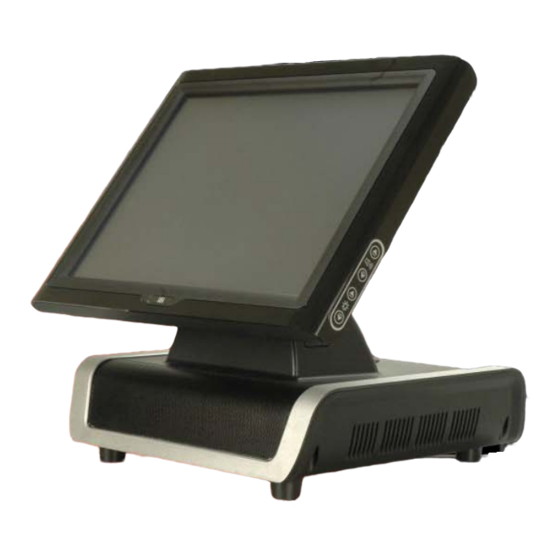
IEI Technology EP-265-GM45 User Manual (139 pages)
Fanless Intel Celeron M Enrich POS System with Touch Panel, 1 GB DDR2, PoweredUSB, VGA, 5 V/12 V Serial Ports and AT/ATX Power Support
Brand:
IEI Technology
| Category:
Touch Panel
| Size: 5 MB
Table of Contents
Table of Contents
5
Packing List
4
1 Introduction
13
Ep-265-Gm45/Ep-267-Gm45 Enrich Pos Overview
14
Applications
15
Features and Model Variations
15
External Overview
16
General Description
16
Monitor Front Panel
16
Figure 1-2: EP-265-GM45/EP-267-GM45 Monitor Front View
16
Figure 1-3: EP-265-GM45/EP-267-GM45 Viewing Angle Adjustment
17
Figure 1-4: EP-265-GM45/EP-267-GM45 Monitor Right Side View
17
I/O Interface Panel
18
Figure 1-5: I/O Interface Connectors on the Monitor Right Side Panel
18
Figure 1-6: EP-265-GM45/EP-267-GM45 I/O Interface Panel
19
Monitor Right Side Panel
17
Chassis Left Side Panel
20
Specifications
20
Preinstalled Hardware Components
20
Figure 1-7: EP-265-GM45/EP-267-GM45 Left Side View
20
System Specifications
21
Table 1-1: EP-265-GM45/EP-267-GM45 System Specifications
23
2 Detailed Specifications
24
Dimensions
25
EP-265-GM45 Dimensions
25
Figure 2-1: EP-265-GM45 Dimensions (MM)
25
EP-267-GM45 Dimensions
26
Figure 2-2: EP-267-GM45 Dimensions (MM)
26
Intel ® Celeron ® M Processor Support
26
Motherboard Components
27
Additional Memory
27
Installed Memory
27
Memory Support
27
Storage Capacity
28
Figure 2-3: CPU and Chipsets Heat Sink
27
External Peripheral Interface Connectors
29
Serial Port Connectors
29
Figure 2-4: Memory Module and Memory Socket
28
Figure 2-5: SATA Hard Disk Drive Bays
28
Figure 2-6: Compactflash® Slot
29
Figure 2-7: COM Ports and LED Indicators
30
LAN Connectivity
30
External USB Connectors
31
Standard USB Connectors
31
Figure 2-8: RJ-45 Ethernet Connector
31
Figure 2-9: External Standard USB Ports
31
Figure 2-10: Poweredusb Ports
32
Figure 2-11: Keyboard and Mouse Connectors
32
Keyboard and Mouse Connectivity
32
Poweredusb Connectors
32
Ep-265-Gm45/Ep-267-Gm45 Front Side
33
Monitor
33
Touch-Screen Module
33
Graphics
33
Intel ® GM45 Integrated Gen 5.0 Graphics Engine
33
Figure 2-12: LCD Screen
33
Audio
34
High Definition Audio Controller
34
Stereo Speakers
34
Figure 2-13: VGA Connector
34
Dual-Display
34
System Power
35
AT Power Mode
35
ATX Power Mode
35
Power Mode
35
Power Connectors
36
Power Supply
36
Figure 2-14: Stereo Speakers
35
Figure 2-15: Power Supply Unit
36
Figure 2-16: Power Connectors
36
Power Input Connector
37
Power Output Connector
37
Connectors for Cash Drawer Power
37
Figure 2-17: RJ-12 Connectors
37
Wireless Ethernet
37
Figure 2-18: Wireless LAN Mini PCI Card
38
Figure 2-19: CPU Heat Sink Air Vent
38
Thermal Management
38
3 Unpacking
39
Unpacking
40
Packing List
41
4 Installation
42
Anti-Static Precautions
43
Installation Precautions
43
Preinstalled Components
44
Installation and Configuration Steps
44
Remove the Bottom Panels
45
Figure 4-1: Monitor Adjustment
45
Cf Card Installation
46
Figure 4-2: Bottom Panel Retention Screws
46
Hdd Installation
47
Figure 4-3: CF Card Installation
47
Figure 4-4: HDD Bracket Retention Screws
48
Figure 4-5: Secure the HDD with the HDD Bracket
48
Jumper Settings
49
Figure 4-6: HDD Installation
49
Figure 4-7: Jumper Locations
49
Access the Jumpers
50
Table 4-1: Jumpers
50
Figure 4-8: Bottom Panel Retention Screws
51
Figure 4-9: Motherboard Chassis Retention Screws
51
Preconfigured Jumpers
52
Cash Drawer Voltage Select
52
Table 4-2: Preconfigured Jumpers
52
Table 4-3: Cash Drawer Voltage Select Jumper Settings
52
CF Voltage Select
53
Table 4-4: CF Voltage Select Jumper Settings
53
Clear CMOS Jumper
54
Figure 4-10: Cash Drawer Voltage Select Jumper Locations
53
Figure 4-11: CF Voltage Select Jumper Location
54
COM3, COM4 and COM5 Pin 9 Select
55
Table 4-5: Clear CMOS Jumper Settings
55
Mounting the Second Display (Optional)
56
Figure 4-12: Clear CMOS Jumper
55
Table 4-6: COM2, COM3 and COM5 Pin 9 Setting Jumper Settings
56
Figure 4-13: COM3, COM4 and COM5 Pin 9 Setting Jumper Locations
56
Figure 4-14: I/O Interface Cover Removal
57
Figure 4-15: Mounting Hole Cover Removal
57
Figure 4-16: Second Display Installation
58
Figure 4-17: Organized Second Display Cables
58
Bottom Panel Switch and Connectors
59
AT/ATX Mode Selection
59
LAN Connection
59
Figure 4-18: AT/ATX Switch
59
Serial Device Connection
60
Figure 4-19: LAN Connection
60
USB Device Connection
61
Figure 4-20: Serial Device Connector
61
Parallel Device Connection
62
Figure 4-21: USB Device Connection
62
Figure 4-22: Parallel Device Connector
63
5 System Maintenance
64
System Maintenance Introduction
65
Anti-Static Precautions
65
Turn off the Power
66
Replacing Components
66
CF Card Replacement
66
Hard Disk Drive Replacement
66
DIMM Module Replacement
67
Figure 5-1: DIMM Socket Location
67
Wireless Module Replacement
68
Figure 5-2: Installing a DIMM
68
Motherboard Replacement
69
Figure 5-3: Wireless Module Location
69
6 Ami Bios Setup
70
Introduction
71
Starting Setup
71
Using Setup
71
BIOS Menu Bar
72
Getting Help
72
Unable to Reboot after Configuration Changes
72
Table 6-1: BIOS Navigation Keys
72
Main
73
System Overview
73
Advanced
74
System Date [XX/XX/XX]
74
CPU Configuration
75
IDE Configuration
76
System Time [XX:XX:XX]
74
SATA#1 Configurations [Compatible]
76
Configure SATA as [IDE]
77
IDE Master and IDE Slave
77
IDE Master, IDE Slave
78
Auto-Detected Drive Parameters
78
Type [Auto]
79
Zip
79
Block (Multi Sector Transfer) [Auto]
80
Lba/Large Mode [Auto]
80
PIO Mode [Auto]
80
DMA Mode [Auto]
81
Auto]
82
Super IO Configuration
83
32Bit Data Transfer [Enabled]
83
Serial Port1 Address [3F8/IRQ4]
83
Parallel Port Address [378]
84
Serial Port2 Address [2F8/IRQ3]
84
Parallel Port IRQ [IRQ7]
85
Parallel Port Mode [Normal]
85
Serial Port3 Address [3E8]
85
Select RS232 or RS422/RS485 [RS232]
86
Serial Port3 IRQ [10]
86
Serial Port4 Address [2E8]
86
Serial Port4 IRQ [10]
86
Serial Port5 Address [2F0]
87
Serial Port5 IRQ [10]
87
Hardware Health Configuration
88
FAN Mode Setting [Full on Mode]
88
CPU Temp. Limit of off [000]
89
CPU Fan Start PWM [070]
90
CPU Temp. Limit of on [020]
90
Slope PWM [0.5 PWM]
90
AHCI Configuration
92
AHCI Port N [Not Detected]
92
AHCI Port N
93
Enabled]
93
Remote Configuration
94
SATA Port N [Auto]
93
Remote Access [Disabled]
94
Base Address, IRQ [3F8H,4]
95
Redirection after BIOS POST
95
Serial Port Mode
95
Serial Port Mode [115200 8,N,1]
95
Serial Port Number
95
Serial Port Number [COM1]
95
Terminal Type
95
Redirection after BIOS POST [Always]
96
Terminal Type [ANSI]
96
USB Configuration
97
USB 2.0 Controller [Enabled]
97
USB Functions [Enabled]
97
Legacy USB Support [Enabled]
98
USB2.0 Controller Mode [Hispeed]
98
Power Configuration
99
IRQ# [Available]
100
Pci/Pnp
100
DMA Channel# [Available]
101
Figure 1-1: EP-265-GM45/EP-267-GM45 Enrich POS
101
Boot
102
Reserved Memory Size [Disabled]
102
Boot Settings Configuration
103
Quick Boot [Enabled]
103
Quiet Boot [Enabled]
103
Addon ROM Display Mode [Force BIOS]
104
Bootup Num-Lock [On]
104
Gbe LAN Boot [Disabled]
104
Change Supervisor Password
105
Change User Password
105
Security
105
Chipset
106
North Bridge Chipset Configuration
107
Memory Hole [Disabled]
107
Boot Display Device [Auto]
108
Flat Panel Type [BY HARDWARE]
108
Southbridge Configuration
109
Internal Graphics Mode Select [Enable, 32MB]
108
HDA Controller [Enabled]
109
Spread Spectrum Mode [Disabled]
109
Cash Drawer Control [Enabled]
110
Restore on AC Power Loss [Last State]
110
Discard Changes
111
Discard Changes and Exit
111
Exit
111
Save Changes and Exit
111
Load Failsafe Defaults
112
Load Optimal Defaults
112
7 System Monitoring
113
IEI Intelligent System Management Module (Ismm)
114
Ismm Features
114
What Is Ismm
114
Figure 7-1: Ismm
114
Com Port Led Indicators
115
Asystem Specifications
116
Motherboard Specifications
117
Processor Specifications
117
Screen Specifications
118
Touch Screen Specifications
119
Wireless Module
119
Power Supply Module
120
External Connector Pinouts
122
Introduction
123
Cash Drawer Connector
123
Power Input Connector
123
B.1 I Ntroduction
123
Vga Connector
124
B.4 Vga C Onnector
124
Csafety Precautions
125
Safety Precautions
126
General Safety Precautions
126
Anti-Static Precautions
127
Maintenance and Cleaning Precautions
127
Maintenance and Cleaning
127
Cleaning Tools
128
Dbios Configuration Options
129
Bios Configuration Options
129
D.1 BIOS Configuration Options
130
D.1 Bios C Onfiguration O Ptions
130
Ewatchdog Timer
133
Example Program
135
Fhazardous Materials Disclosure
136
Hazardous Material Disclosure Table for IPB Products Certified as Rohs Compliant under 2002/95/EC Without Mercury
137
Advertisement
Advertisement
Related Products
IEI Technology EP-267-GM45
IEI Technology EP-267-910
IEI Technology EP-265-910
IEI Technology EP-308A
IEI Technology eKINO-945GSE
IEI Technology ECW-281BB6
IEI Technology ECW-281B-945GSE
IEI Technology ECK-1000 Series
IEI Technology ECK-1000-9453
IEI Technology ECW-281B2-D525
IEI Technology Categories
Motherboard
Touch Panel
Computer Hardware
Single board computers
Desktop
More IEI Technology Manuals
Login
Sign In
OR
Sign in with Facebook
Sign in with Google
Upload manual
Upload from disk
Upload from URL