Table of Contents
Advertisement
Quick Links
Advertisement
Table of Contents
Troubleshooting

Subscribe to Our Youtube Channel
Related Manuals for SMART Board 3000i


Summary of Contents for SMART Board 3000i
- Page 1 Installation Guide SMART Board 3000i Interactive Whiteboard...
-
Page 2: Technical Support
SMART. Information in this guide is subject to change without notice and does not represent a commitment on the part of SMART. -
Page 3: Important Information
Assurez-vous qu’une prise secteur se trouve à proximité du 3000i et demeure facilement accessible durant l’utilisation. Asegúrese de que hay una toma de corriente alterna cerca del 3000i y que es fácilmente accesible para su uso. Stellen Sie sicher, dass sich in der Nähe des 3000i eine Steckdose befindet und sie während der Verwendung auch leicht zugänglich bleibt. - Page 4 Si vous avez des doutes sur le type de système d’alimentation disponible lors de l’installation de votre 3000i, contactez un personnel qualifié. La 3000i sólo se podrá utilizar con los sistemas eléctricos TN y TT ADVERTENCIAS Para los clientes europeos.
-
Page 5: Other Precautions
• When you transport the 3000i, only ship it in an upright position and never lay the interactive whiteboard face down. In addition, ensure that the projector is secure, or remove and repackage it in the original projector’s packaging. - Page 6 • Avoid setting up and using the 3000i in an area with excessive levels of dust, humidity or smoke. •...
-
Page 7: Table Of Contents
Important Information .................... i Other Precautions ....................iii About the 3000i ..................... 1 3000i Features ...................... 1 Getting to Know Your 3000i .................. 2 Pen Tray Features ....................3 The NEC VT670 Projector ..................4 Control Panel ......................6 Rear Features ....................... 8 Connection Panel .................... - Page 8 Appendix E: Connecting a Guest Laptop ............67 Installing the Guest Laptop Shelf ................ 67 Installing the J-hook .................... 69 Connecting the Laptop Umbilical to the 3000i Cabinet ........70 Connecting the Laptop Umbilical to a Guest Laptop .......... 71 Changing the Display Source ................72 Index ........................
-
Page 9: About The 3000I
Internet sites, play video clips, and so on—simply by touching the interactive whiteboard. You can also write over any live application in digital ink using a pen tray pen or your finger, and then save your notes to a SMART Notebook™ file for future reference and distribution. -
Page 10: Getting To Know Your 3000I
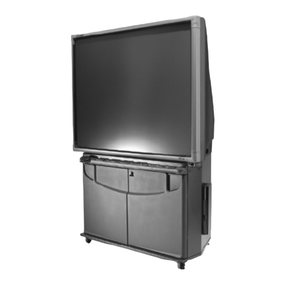
Getting to Know Your 3000i Lockable Doors Lockable Casters (x 4) SMART Super Screen SMART Pen Tray Control Panel Manual Pocket Your Computer Projector Platform (with round-hole, rack-mounting rails) About the 3000i... -
Page 11: Pen Tray Features
Dock (Macintosh computers), select Control Panel, and press on Pen Tray Settings. NOTE: The pens provided with your 3000i have black tips because the digital cameras in the bezel can more readily detect dark objects. If you need to use a different object to point at the screen, choose one that has a dark tip but which won’t mark or damage the interactive screen. -
Page 12: The Nec Vt670 Projector
Again, contrary to the NEC VT470/570/670 User’s Manual, the Zoom lever will not adjust the image size on the screen. The NEC projector featured in the 3000i rear projection cabinet is an NEC VT670. The VT670 projector has XGA resolution (1024 × 768). - Page 13 To set or restore the optimal settings for the NEC VT670 projector We’ve configured your projector settings for optimal performance with the 3000i. However, if these settings are accidentally altered, follow the procedure below to restore them. 1. Press the Menu button on the projector remote control or the Menu button on the projector.
-
Page 14: Control Panel
Off button for three seconds. To turn on the projector lamp, press the Lamp On button. CAUTION The projector inside the 3000i has been designed for use under normal operating conditions only. Normal operating conditions are defined as product use that does not exceed 8 hours per day and 260 days per year. Exceeding these operating conditions could cause projector damage. - Page 15 Source Buttons Use the source buttons to switch the video and audio sources for the projector and cabinet audio amplifier. Button Source VCR/DVD player Internal computer Guest laptop (only with the optional Guest Laptop Support kit) Notebook software. About the 3000i...
-
Page 16: Rear Features
Rear Features Close-up of Connection Panel About the 3000i... -
Page 17: Connection Panel
Connection Panel The Connection Panel allows you to make a variety of external connections to the 3000i cabinet: • A printer (1), dedicated to the internal computer • A network (2), making the full resources of the network available to the internal computer •... -
Page 18: Main Power Input And Power Outputs
The Main Power IN and Power OUT connections are located to the right of the Connection Panel (as you face the rear of the cabinet). • The Main Power IN provides power to the 3000i unit. • The Laptop Power OUT may be used in conjunction with the optional Guest Laptop Support kit to provide power to a guest laptop. -
Page 19: Installation
As a safety precaution and for greater ease of use, the casters should remain locked while the 3000i is in use. 3. Open the front doors and then unbuckle and remove the strap that secures the small mirror. -
Page 20: Removing The Rear Access Panel
The small mirror is strapped securely in place to protect it during shipment. You must remove this strap prior to use. Remove this strap Location of Small Mirror Strap Removing the Rear Access Panel You must remove the rear access panel before you install your internal computer. Once you’ve turned on the projector and internal computer, you should replace the rear access panel—as well as lock the cabinet front doors—as a security precaution. -
Page 21: Installing And Connecting The Internal Computer
To remove the rear access panel 1. Loosen the two captive thumbscrews at the top of the rear access panel. Captive Thumbscrew Captive Thumbscrew 2. Rotate the top of the rear access panel toward you and then pull it upwards, releasing it from the cabinet. -
Page 22: Turning On The Projector And The Computer
PS/2 keyboard port (identified by a keyboard symbol). To connect the power cable Connect the AC cord in the accessory box to the power inlet at the rear of the 3000i. Then connect this AC cord to an available power outlet or power bar (not supplied). -
Page 23: Connecting To A Vcr And/Or Dvd Player
Button The Control Panel NOTE: For more information about turning on the 3000i, see page 29. 4. When an image displays, adjust the computer power settings and the image alignment on the interactive screen. Then install the SMART Board software CD, configure the COM port, and perform a brief orientation procedure. - Page 24 To connect to a VCR 1. Turn off the VCR. 2. Connect the RCA composite video cable bundled inside the cabinet to the Video OUT jack on the VCR. This jack may be labeled “To Monitor”. NOTE: If your VCR has an S-video output, you can connect the S-video cable bundled inside the cabinet to the VCR.
- Page 25 6. Press the VCR/DVD Player button on the Control Panel. VCR/DVD Player Button 7. Turn on the DVD player and press the Play button. To link VCR and DVD player audio connections NOTE: Make sure there is no tape in the VCR before you proceed. 1.
-
Page 26: Connecting To A Printer
Connecting to a Printer To connect to a printer Connect a standard DB25 printer cable (not provided) from the printer’s parallel port to the Printer Connector on the Connection Panel. Printer Network Printer Connector Audio OUT Output Audio IN VCR/DVD Audio OUT Computer 2 Serial Computer 2 Inputs Connecting to a Network... -
Page 27: Connecting To An External Sound System
Connecting to an External Sound System To connect to an external room sound system Connect standard red and white RCA audio cables (not provided) from the RCA Audio Inputs on the external sound system to the two Audio OUT (L/R) jacks on the Connection Panel. Keep your right and left channel connections correct for stereo sound. - Page 28 Installation...
-
Page 29: Finalizing The Installation
(page 26) • orienting the interactive whiteboard (page 26) After you’ve made these adjustments and configurations, your 3000i is ready to use. Adjusting the Projected Image CAUTION Do not adjust the white ring that surrounds the short-throw, customized projector lenses, even though the NEC VT470/570/670 User’s Manual states... - Page 30 3. Tighten or loosen the knobs on the left of the projector plate until you have the required roll adjustment. Adjust these knobs by the same amount or else you will change the vertical adjustment of the image (page 23). NOTE: If you can’t tighten the knobs on the left of the projector plate, you can adjust the roll by loosening the knobs on the right of the projector plate 4.
- Page 31 5. Tighten the four knobs. 6. Tighten the three screws that you loosened in step 2. To change the image size 1. Locate the three security screws in the projector plate. These are illustrated in the figure below. 2. Loosen these screws using the TORX® key in the accessory kit. 3.
-
Page 32: Configuring The Computer Settings
Your projector goes into standby mode if it doesn’t receive a video signal for 30 minutes. Even though the projector and the 3000i are in standby mode, you can press the Lamp On button to quickly return both units to their normal operating states. -
Page 33: Installing Smart Board Software
2. Press Yes to install the SMART Board icon in the Startup folder, or press No to prevent SMART Board software from starting whenever you turn on your system. -
Page 34: Configuring The Computer Port
Windows operating system fails to announce that it has Found New Hardware To select a COM port for the interactive whiteboard 1. Press the SMART Board icon in the system tray (Windows computers) or in the Dock (Macintosh computers), and select Control Panel. - Page 35 (page 40). To orient using the Fine (20-point) or Quick (4-point) orientation levels 1. Press the SMART Board icon in the system tray (Windows computers) or in the Dock (Macintosh computers), and select Control Panel. 2. Select SMART Board Settings.
- Page 36 Finalizing the Installation...
-
Page 37: Basic Operations
For ease of operation, you should also keep the computer on all the time. By doing this, you can turn on the 3000i by restoring power to the projector lamp (press the Lamp On button on the Control Panel) and then entering your user name and password at the logon screen. -
Page 38: Startup Scenarios
Startup Scenarios The following table describes what you may need to do to restore the 3000i to a fully operational state. What You See What You Should Do • Screen is black The projector is in standby mode (with the lamp off). -
Page 39: Putting The 3000I Into Standby
(page 24). NOTE: If you won’t use the 3000i for an extended period of time, you should turn off the computer and the projector. -
Page 40: Adjusting The Volume
Volume adjustments are made for the active display source and are made independently of other sources. When you switch to another input source, the 3000i retains the settings you made for the first input source (for when you switch back). -
Page 41: Changing The Display Source For The Internal Projector
To fine-tune the projected image When you first connect the projector, you may need to fine-tune the image. To automatically optimize the image in RGB mode, press the Auto Adjust button on the projector’s remote control. This will eliminate vertical banding, flickering, video noise, dot interference and cross talk. -
Page 42: Using The Smart Board Interactive Whiteboard
SMART Board software. However, to get the most from your 3000i, open the SMART Board tools. You’ll know that the tools are active if you can see the SMART Board icon in the system tray (Windows computers) or in the Dock (Macintosh computers). SMART Board software lets you customize the pen tray tools. - Page 43 • the Floating Tools, a virtual palette of annotation tools • the SMART Board Control Panel, a utility that lets you configure the interactive whiteboard, including the pen tray tools SMART Notebook software Notebook software lets you create a variety of annotations and import graphics, text, clip art and entire files from any other application.
- Page 44 Basic Operations...
-
Page 45: Maintenance And Troubleshooting
Do not spray glass cleaner directly onto the screen surface. Instead, spray it lightly on a cloth and then gently wipe. The 3000i uses digital cameras that are located inside the frame. If excess glass cleaner flows into the crack between the frame and the writing surface, the fluid could damage the cameras. -
Page 46: Replacing The Projector Lamp And Filter
You should also replace the air filter with the new one that you’ll receive with the replacement lamp. Order the standard lamp from NEC. Alternatively, you can order the same lamp from your SMART dealer. Ask for SMART P/N 01-00161. Do not use any other lamps. NOTES •... -
Page 47: Troubleshooting
Allow it to cool for three minutes, and then disconnect the main AC power cable from the room outlet. To restore power to the 3000i, wait another 15 seconds and then plug the AC power back in. Then turn on the computer and projector. -
Page 48: Calibrating The Cameras
The following table may help you resolve some of the more common 3000i problems. Problem Cause Possible Resolution There’s no touch control on Software Make sure SMART Board software is the interactive screen problem running. Is there a SMART Board icon in the System Tray or the Dock? If not, you’ll need to start the program. - Page 49 Fortunately, this problem is easily fixed by performing a simple calibration procedure, as described below. To calibrate the cameras 1. Press the SMART Board icon in the system tray (Windows computers) or in the Dock (Macintosh computers), and select Control Panel. 2. Press SMART Board Settings.
- Page 50 Maintenance and Troubleshooting...
-
Page 51: Customer Support
Contacting SMART Technical Support SMART’s Technical Support team welcomes your call. However, you may first want to contact your local reseller if you experience any difficulty with your 3000i, as they may be able to solve the problem without delay. -
Page 52: Registration
NOTE: After the warranty period, you are responsible for transporting the product to and from the service center. Registration A User Registration card was included with your 3000i. To help us serve you, fill in and mail this card to SMART Technologies Inc. or register online at www.smarttech.com/registration. Sending Feedback You can help us improve our technical documentation by e-mailing your comments to TechnicalDocumentation@smarttech.com. -
Page 53: Appendix A: Removing The Side Panel, Screen And Cabinet Top
Appendix A: Removing the Side Panel, Screen and Cabinet Top Remove the side panel to access a number of important components such as the projector, SC8 controller and the Communications Hub. CAUTION Never touch the back of the screen or brush against it with your head while you’re examining internal cabinet components. - Page 54 3. On the left side of the cabinet (as you face the rear), use the provided 5/32" hex key (located in the accessory kit) to remove the hex screw on the top corner of the interactive whiteboard. 4. Using the same hex key, remove the hex screw underneath the bottom corner of the interactive whiteboard.
- Page 55 5. Remove the two hex screws on the rear of the cabinet. 6. Grip the side handle and the top of the cabinet and pull the side panel off. NOTE: To remove the screen, continue with the remaining numbered steps. Appendix A: Removing the Side Panel, Screen and Cabinet Top...
- Page 56 To remove the screen (continued from previous procedure) 1. Reach inside the cabinet to disconnect the MOD8 and power cables at the bottom of the screen. Don’t touch the back of the screen. Disconnecting MOD8 and Power Cables 2. Loosen the four captive fasteners on the back corners of the interactive whiteboard using a Phillips®...
- Page 57 3. With one person on each side, grasp the screen by the top and bottom corners. Lift the screen up and then out to free it from the two keyhole slots that support it. Set the screen down in a safe location. Removing the Screen Never touch the back of the screen or brush against it with your head.
- Page 58 2. Using the same hex key, loosen and then remove the two safety screws located on the underside of the top half of the cabinet, on either side of the pen tray and Control Panel. Location of Underside Safety Screw 3.
-
Page 59: Appendix B: Removing And Replacing The Projector
Appendix B: Removing and Replacing the Projector To remove the projector (for example, to replace the lamp), you must remove the 3000i’s left side panel and its rear access panel, disconnect the projector’s cables and detach the projector from the projector plate. - Page 60 3. On the right side of the cabinet (as you face the rear), use the provided 5/32" hex key (located in the accessory kit) to remove the hex screw on the top corner of the interactive whiteboard. 4. Using the same hex key, remove the hex screw underneath the bottom corner of the interactive whiteboard.
- Page 61 5. Remove the two hex screws on the rear of the cabinet. 6. Grip the side handle and the top of the cabinet and pull the side panel off. Put the side panel in a safe place. 7. Reach inside the cabinet and unfasten the two projector straps. Never touch the back of the screen or brush against it with your head while CAUTION you're examining internal unit components.
- Page 62 8. At the rear of the cabinet, loosen the two captive thumbscrews at the top of the rear access panel. Captive Thumbscrew Captive Thumbscrew 9. Rotate the top of the rear access panel toward you and then pull it upwards, releasing it from the cabinet.
- Page 63 WARNING Do not touch or replace the projector lamp (which will be very hot) for at least an hour after turning off the 3000i. To replace the projector 1. Lift the projector into the cabinet through the side panel. Lower it onto the projector plate so that the screws go through the keyhole slots.
- Page 64 2. From the rear of the cabinet, slide the projector forward until the three screws are in the three marked positions. You made these marks on the projector plate before you removed the projector. Tighten the three screws using the TORX key in the accessory kit.
- Page 65 4. Fasten the two projector straps. 5. Reattach the rear access panel to the rear of the cabinet. Tighten the two thumbscrews at the top of the rear access panel. Captive Thumbscrew Captive Thumbscrew 6. Reattach the side panel to the side of the cabinet. Appendix B: Removing and Replacing the Projector...
- Page 66 7. Attach and then tighten the two hex screws on the rear of the cabinet using the provided 5/32" hex key. 8. Attach and then tighten the hex screw underneath the bottom corner of the interactive whiteboard using the same hex key. Appendix B: Removing and Replacing the Projector...
- Page 67 9. Attach and then tighten the hex screw on the top corner of the interactive whiteboard using the same hex key. 10. If you removed the guest laptop from the left side of the cabinet, reinstall it following the instructions on page 67. Appendix B: Removing and Replacing the Projector...
- Page 68 Appendix B: Removing and Replacing the Projector...
-
Page 69: Appendix C: Connecting Rack-Mount Equipment To The Projector Platform
Appendix C: Connecting Rack-Mount Equipment to the Projector Platform Use the provided clip-on nuts to secure the rack-mount equipment to the sides of the projector platform, just below the projector itself. The projector platform can accommodate rack-mount equipment with a width of 19" (48.3 cm). To connect rack-mount equipment to the projector platform 1. - Page 70 Appendix C: Connecting Rack-Mount Equipment to the Projector Platform...
-
Page 71: Appendix D: Installing The Optional Videoconferencing Shelf
Appendix D: Installing the Optional Videoconferencing Shelf You can install the optional 3000i videoconferencing shelf on either side of the cabinet. The mounting arm of the shelf provides a convenient hidden channel for the camera cabling. Installed Videoconferencing Shelf To install the videoconferencing shelf 1. - Page 72 2. Remove the four caps and plugs from the mounting arm at the location where you want to mount the shelf. Feed the cables for the videoconferencing camera through the large hole, down the channel and through the lower mounting point. NOTE: The cables shown here may not match those required by your videoconferencing camera.
- Page 73 4. Use the three supplied 1/4-20 × 3/4" fasteners in place of the 1/4-20 × 1/2" fasteners (removed in step 1) to secure the mounting arm to the cabinet. The safety screw is now replaced. NOTE: Now that you’ve replaced the safety screw, you can safely move the cabinet. 5.
- Page 74 6. Use the J-hook to manage the cables along the side of the cabinet. Clip the J-hook onto the handle on the side of the 3000i and route the cables through that hook to the Connection Panel at the rear of the cabinet.
-
Page 75: Appendix E: Connecting A Guest Laptop
3000i. This kit connects your laptop to a multimedia switch inside the 3000i called an X-Port 20. Once your laptop is connected in this manner, you can switch the source of the 3000i’s data input between the 3000i’s internal computer and the guest laptop. - Page 76 To install the guest laptop shelf 1. Locate the two laptop shelf keyholes and the single thumbscrew hole on the upper right (or left) side of the cabinet. Remove the plastic hole covers. 2 Keyholes Thumbscrew Hole 2. Push the two protruding bolts on the edge of the shelf into the two keyholes, and then push the shelf firmly down.
-
Page 77: Installing The J-Hook
Installing the J-hook You can attach the J-hook to the handle recess so you can route the umbilical cables through this hook to the guest laptop shelf. You’ll find this hook in the accessory kit. To attach the J-hook 1. Insert the J-hook into the handle recess that’s on the same side of the cabinet as the guest laptop shelf, and flip it into place. -
Page 78: Connecting The Laptop Umbilical To The 3000I Cabinet
Connecting the Laptop Umbilical to the 3000i Cabinet To attach the laptop umbilical to the cabinet, use the following instructions. To connect the laptop umbilical to the 3000i cabinet 1. Connect the serial end of the laptop umbilical’s Serial/USB adapter to the Computer 2 Serial IN connector on the Connection Panel at the rear of the cabinet. -
Page 79: Connecting The Laptop Umbilical To A Guest Laptop
To connect the 3000i to the guest laptop, use the laptop umbilical that you have already connected to the cabinet. To connect the laptop umbilical to a guest laptop 1. Extend the laptop end of the umbilical from the rear of the 3000i cabinet until it reaches the laptop shelf. Computer 2 Network... -
Page 80: Changing The Display Source
2 Network, Computer 2 Audio, Computer 2 Video, Computer 2 USB and AC Power cables—to the appropriate connectors on the guest laptop. If the guest laptop is already turned on, the desktop image will appear on the 3000i screen. 4. If the laptop is off, turn it on. - Page 81 To switch to a different display source, press the Internal Computer button or press the VCR/DVD Player button on the Control Panel. Internal (Host) Computer Guest Laptop VCR/DVD Player NOTE: Switching sources takes a few seconds and, during that time, all buttons on the Control Panel are disabled.
- Page 82 Appendix E: Connecting a Guest Laptop...
-
Page 83: Index
Connecting Features 1 DVD Player 15 Introduction 1 External Monitor 19 Orienting 26 External Projector 19 Putting the 3000i into Standby 31 External Sound System 19 Setting up 11 Guest Laptop 71 Turning on 29 Internal Computer 13 Using 34... - Page 84 Connecting an External Monitor 19 Focus Monitor Settings 24 Adjusting Projector Focus 5 NEC VT670 4 General Inquiries 43 Network Getting to Know the 3000i 2 Connecting 18 Guest Laptop Normal Operating Conditions iii Connecting 71 Notebook Software 35 Switching 34...
- Page 85 Restoring Optimal Projector Settings 5 Side Panel Turning off 32 Removing 45 Turning on 14 SMART Board Interactive Whiteboard See 3000i 1 Putting the 3000i into Standby 31 SMART Board Software Installing 25 SMART Board Tools 34 SMART Notebook Software 35...
- Page 86 Connecting 15 Linking VCR and DVD Player Audio Connections 17 Switching to the Connected VCR 33 Videoconference Shelf Installing 63 Volume Adjusting 32 Restoring Default Settings 32 Index...
- Page 87 Suite 300, 1207 – 11th Avenue SW Calgary, AB CANADA T3C 0M5 Main Switchboard: 1.888.42.SMART (Canada/U.S.) or +1.403.245.0333 (all other countries) Support Tel.: 1.866.518.6791 (Canada/U.S.) or +1.403.228.5940 (all other countries) Support Fax: +1.403.806.1256 support@smarttech.com www.smarttech.com 99-00224-06 REV A0...
Need help?
Do you have a question about the 3000i and is the answer not in the manual?
Questions and answers