Table of Contents
Advertisement
Quick Links
Advertisement
Table of Contents

Subscribe to Our Youtube Channel
Related Manuals for Kathrein MSK 25


Summary of Contents for Kathrein MSK 25
- Page 1 Instruction Manual MSK 25 Satellite/TV/FM Test Receiver analogue/digital...
-
Page 2: Preface
This in particular applies to modifications which suit the technical progress. All product names and trademarks in this manual are the property of the respective firms. All rights reserved. Validity: This manual applies for the MSK 25. Date of issue: Sept. 2005... -
Page 3: Table Of Contents
Contents Contents Preface... 2 Contents ... 3 General Information... 5 Signs and Symbols ... 5 Safety Rules... 5 Functionality ... 6 Overview of Functions ... 7 Technical Data ... 9 Control Elements and Indicators ... 11 Control Elements... 11 TFT Colour Screen ... 11 Connections (right hand side) ... - Page 4 Technical Appendix... 47 Signal-to-Noise-Ratio ... 47 DiSEqC™ Commands for Kathrein Matrices ... 48 Instruction Set for 9xx Kathrein Matrix Production Run ... 48 Instruction Set for EXR 20 Kathrein Matrix ... 48 Instruction Set for EXR 22 Kathrein Matrix ... 48 Channel Tables ...
-
Page 5: General Information
Always adhere to the instructions classified with the warning signal carefully, as otherwise the MSK 25 test receiver may be damaged or even be destroyed. This symbol provides information on measuring functions and refers to chapters containing further particulars on a subject. -
Page 6: Functionality
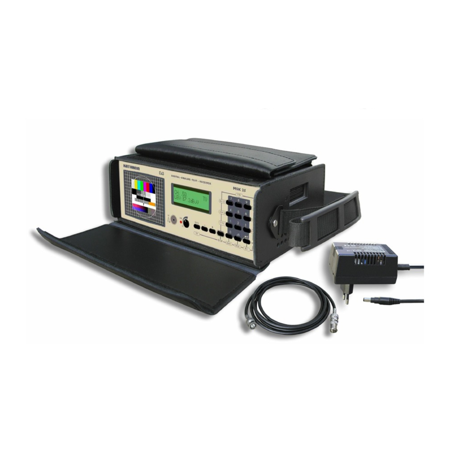
Functionality The MSK 25 has been conceived as a portable test receiver for TV, SAT and FM radio measurements, as well as for DVB-C, DVB-S and DVB-T in both, battery operation and mains operation. The built-in lead battery (3.4 Ah) and a wall power supply with a built-in charger, suitable for 230 VAC, are included in delivery. -
Page 9: Technical Data
Technical Data Technical Data Power supply Mains operation Battery operation Dimensions Weight Safety standards Display Temperature range Frequency range Channel configuration Frequency tuning Measurement error RF input RF input reducer Level measurement range Measurement bandwidth Measuring detector Voltage standing wave ratio FM threshold Audio-IF bandwidth Audio Deemphasis... - Page 10 Technical Data B/G standard D/K standard I standard M/N standard M1 standard L standard B/G standard I standard FM audio processing Sound carrier measurement Nicam decoder Sound carrier distance Nicam BER DVB-S modulation method DVB-C modulation method DVB-T modulation method DVB-S-MER DVB-C-MER DVB-T-MER...
-
Page 11: Control Elements And Indicators
Control Elements and Indicators Control Elements and Indicators TFT colour screen LC display Control Elements FR: 954.0 MHz LEV: 40.0 dBuV TFT Colour Screen Connections (right hand side) HF input socket LED volume control The following is displayed on the two-row 16 digit LC display, depending on the mode: •... -
Page 12: Short Cut Overview
Short Cut Overview Short Cut Overview SAT/DVB-S Change-over to SAT/TV TV reception Decimal point for numeric character entry ENTER 2ndF + key Sat-Ctrl Call-up of DiSEqC™ menu / LNB voltage menu and current measurement Ch-Freq No function DVB-S/analogue change-- over DVB-S measurement MER, BER, OFFSET *MPEG programme... -
Page 13: Connections
The MSK 25 may either be mains operated or battery operated (batteries built-in). The external voltage supply is carried out via the DC socket at the right side of the MSK 25 box, with the wall power supply and the charger, both included in delivery. Sustained continuous operation (incl. -
Page 14: Commissioning
Commissioning Commissioning Switching-Up Software V2.0 SN: 000222 ACCU [−−−−−] CH: .02. LEV: 48.5dBuV Switching-Off • Connect the instrument to the mains with the wall power supply. • Turn the on/off switch to the right. • Adjust the desired volume. The LC display will then indicate the particular software version for appr. 1 second. -
Page 15: Setup-Menu
LOW LEVEL MUTE 1=OFF 2=ON 4. Setup menu CH: .07. LEV:____.__dBµV Basic setting The basic setting (status of the MSK 25 after switching it on) can be set in the Setup menu. Parameter POWER ON LNB DC LEVEL Low Level Mute Press [2ndF] and [SETUP]. -
Page 16: Mains Operation And Battery Operation
25 to the mains supply occasionally (trickle charge). Make sure that the wall power supply is not connected to the instrument but for voltage feed. Otherwise the battery of the MSK 25 will be discharged! Battery operation is only possible if the battery is sufficiently charged. -
Page 17: Sat Measurement
1=27500 2=24500 3=22000 4= USER Standard menu FR:1288.0MHz LEV: 66.5dBuV Display for DVB-S measurement In SAT mode, the MSK 25 receives • analogue signals and • DVB-S signals. [2ndF] [STD] calling up menu standard change-over: [1] to [2] select standard... -
Page 18: Frequency Display And Frequency Entry
• level: 86.5 dBµV (A = analogue) The indicaton „+“ or „–“ on the display means that the MSK 25 has not been exactly tuned to the carrier required. Bei pressing either [+] or [-], the frequency can be finetuned for optimum reception. This has been achieved when a vertical line appears on the display. -
Page 19: Sat Analogue Level Measurement
SAT measurement SAT Analogue Level Measurement FR:1508.0MHz LEV: 86.5dBuV A │ Level Overflow and Level Underflow FR:1508.0MHz LEV: __._dBuV A │ FR:1508.0MHz LEV: ¯¯˙¯dBuV A │ Note SAT DVB-S Level Measurement FR:1236.0MHz LEV: 86.5dBuV Once you have entered a frequency, the level is measured automatically and displayed either in dBµV or dBmV (depending on the basic configuration) on the LC display. -
Page 20: Locating Satellites
SAT measurement Locating Satellites SCAN Menu LEV-Range:2 > ■■■■ Example With the SCAN function, satellites, the exact transponder frequencies of which are unknown, can be located. In doing so, the frequency range from 1000 MHz to 2100 MHz is continuously scanned for received signals. -
Page 21: Bearing For Individual Reception Frequencies
SAT measurement Bearing for Individual Reception Frequencies Bearing Menu LEV-Range:2 > ■■■■ Example Exit: The „LEVEL ♫“ function allows the antenna alignment to maximum received signal via bearing. The level tendency can be bargraph- displayed.The measurement range can be adjusted to three different sensitivity levels. -
Page 22: Sat Analogue Sound Carrier Frequency
Sound carrier bandwidth: narrow = 150 kHz • Mode: SAT After SAT mode has been called up, the MSK 25 will be permanently adjusted to sound carrier 7.02 MHz. Frequency variations of the sound carrier will not be retained after SAT mode has been closed. -
Page 23: Dvb-S Mer, Ber And Offset Measurement
SAT measurement DVB-S MER, BER and Offset Measurement MER:12.6dB BER:1.7e-7 + 0.72 MPEG Picture Representation (option) in DVB-S Press [2ndF] to exit digital reception. Note ☞ The modulation error rate (MER), the bit error rate (BER) and the carrier offset can be measured to rate the digital reception quality. Chapter ‚standard change-over‘... -
Page 24: Lnb Voltage And 22 Khz/60 Hz Change-Over
SAT measurement LNB Voltage and 22 kHz/60 Hz Change-Over LNB Voltage Menu Examples LNB:14,0V 150mA Note The LNB supply voltage can be obtained from the RF socket. For checking purposes, the LED beside the RF socket flashes when the voltage supply is switched on. The power consumption of the connected LNB is displayed on the LCD. - Page 25 SAT measurement Example LNB:14,0V 22kHz 150mA Note Activating the 22 kHz signal: Press [2nF] [LNB] [8] LC display: • LNB voltage: 14 V • Power consumption: 150 mA • 22 kHz signal activated By pressing [8] again, the 22 kHz signal can be deactivated. By calling up a different function, e.
-
Page 26: Diseqc™ (Digital Satellite Equipment Control)
DiSEqC™ Menu Framing Address MSK 25 can emit signals to DiSEqC™1.0, however, it cannot receive signals. [2ndF] [SAT-CTRL] Calling up DiSEqC™ menu You will find the main DiSEqC™ commands for four satellite positions... -
Page 27: Framing Byte Menu
Framing Byte Menu Example for a USER entry You wish to check the EXR 22 KATHREIN matrix. The instruction set for the EXR 22 matrix is E0 00 24 (LNB High) and E0 00 20 (LNB Low). Calling up DiSEqC™: Press [2ndF] [SAT-CTRL] Press [0] to call up USER entry. -
Page 28: Address Byte Menu
SAT measurement Address Byte Menu Hex Byte Description All instruments Every LNB, Matrix or SMATV LNB with loop-through Matrix (Switcher) Matrix (Switcher) with loop-through SMATV Every polarizer Maximum turning (full skew) in linear polarisation Stepwise polarizer adjustment Every positioner Polar/Azimuth positioner Elevation positioner Combined positioner LNB Positioner... -
Page 29: Command Byte Menu
Read A1 Write A0 Write A1 MSK 25 can send commands under DiSEqC™ 1.0 but cannot receive them. All the commands requiring DiSEqC™ 2.0 (sending and receiving) are underlined grey in the table below. Commands in bold are particularly preferred for KATHREIN switching matrices. - Page 30 SAT measurement Write A7 LO string LO now LO Lo LO Hi Write Freq Ch.No. Halt Go E Go W P Status Read Pos Goto Write Pos Set analogue value A7 Read current frequency Read current frequency (Table Entry Number) Read Lo frequency table entry number Read Hi frequency table entry number Write channel frequency...
-
Page 31: Data Byte Menu
SAT measurement Data Byte Menu Simple Tone Burst DiSEqC™ Simple DiSEqC™ Menu A corresponding data byte need not be sent to a command byte unless required by the command byte data byte(s). You can see this from the preceding command byte table. Please learn from the data sheets of the respective instruments which data byte is to be sent to the particular command byte. -
Page 32: Tv Measurement
Standard Change-Over TV Menu Example 1=ANALOG 3=DVBT 2=DVBC 0=Std. 1=BG 3=DK 5=MN 6=M1 Standard menu Note In TV mode, the MSK 25 can measure the following standards: • B/G standard • L standard • D/K standard • I standard • M/N standard •... -
Page 33: Dvb-C/Dvb-T Change-Over
TV measurement DVB-C/DVB-T Change-Over 1=ANALOG 3=DVBT 2=DVBC 0=Std. 1=QAM64 2=QAM128 3=DOC64 1=6.900 2=6.952 3=6.875 4=USER Press [2ndF] [STD]. LC display: • 1 = Analogue reception • 2 = DVB-C reception • 3 = DVB-T reception (if this option is provided) •... -
Page 34: Channel Display And Channel Entry
TV measurement Channel display and channel entry TV Channel Setting Menu Example CH:S.11. LEV: 62,5dBuV Note You first have to set the required channel to be able to measure the level of a TV reception signal. The following channels may be set: •... -
Page 35: Frequency Display And Frequency Entry
If you had called up the frequency menu before, you now only need to enter the figures in order to enter a frequency. The last frequency entry will be retained even after you have switched off the MSK 25, provided that the entry was carried out via numeric character input, ending with ‚MHz‘... -
Page 36: Level Measurement Tv Analogue
TV measurement Level Measurement TV Analogue CH: .05. LEV: 86.5dBuV Level Overflow and Level Underflow CH: .05. LEV:___._dBuV CH: .05. LEV:.dBuV Note TV/DVB-C/DVB-T Level Measurement CH:S.32. LEV: 64.0dBuV After you have set a channel or a frequency, the level is automatically measured and displayed on the LC display either in dBµV or in dBmV (depending on the basic configuration). -
Page 37: Bearing For Individual Reception Frequencies
TV measurement Bearing for Individual Reception Frequencies Bearing Menu LEV-RANGE:2 > ■■■■ Example The „LEVEL ♫“ function allows the antenna alignment to maximum received signal via bearing. The level tendency can be bargraph- displayed. The measurement range can be adjusted to three different sensitivity levels. -
Page 38: Sound Carrier Distance And Sound Carrier Level
TV measurement Sound Carrier Distance and Sound Carrier Level TV Sound Carrier Measurement Menu Example SC: 5,50MHz LEV: -13.0dB SC: 5,50MHz LEV: 58,5dBuV On a second sound carrier, TV broadcast stations can transmit either frequency-modulated (analogue) or in Nicam format (digital). Depending on the standard which has been set, various frequencies are assigned to the sound carriers, see table. -
Page 39: Nicam Sound Bit Error Rate Measurement
TV measurement Note NICAM Sound Bit Error Rate Measurement Example SC: 5.85 MHz BER=2.145E-05 Press [3] while the sound carrier is displayed The sound carrier frequency is not adjustable but changed over according to the standard which has been set. The sound carrier level is only displayed when key [2] or [3] is pressed. -
Page 40: Dvb-C/Dvb-T (Option), Mer, Ber And Offset Measurement
TV measurement DVB-C/DVB-T (option), MER, BER and Offset Measurement MER:30.5dB BER:2.0e-8 0.00 MPEG Picture Representation (option) in DVB-C or DVB-T (option) Note ☞ The modulation error rate (MER), the bit error rate (BER) and the carrier offset can be measured to evaluate the quality of the digital reception. Chapter ‚standard change-over‘... -
Page 41: Fm Measurement
If you had called up the FM menu before, you now only need to enter the figures in order to enter a frequency. The last frequency entry will be retained even after you have switched off the MSK 25, provided that the entry was carried out via numeric character input, ending with ‚MHz‘. -
Page 42: Level Measurement
FM measurement Level Measurement Fr:104.80MHz LEV: 86.5dBuV A │ Level Overflow and Level Underflow FR:104.80MHz LEV: ___._dBuV A │ FR:104,80MHz LEV:¯¯¯.¯dBuV A │ After you have set a frequency, the level is automatically measured and displayed in dBµV. The input level can be measured in the range of 30 dBµV to 120 dBµV. -
Page 43: Bearing For Individual Reception Frequencies
FM measurement Bearing for Individual Reception Frequencies Bearing Menu LEV-RANGE:2 > ■■■■ Example The „LEVEL ♫“ function allows the antenna alignment to maximum received signal via bearing. The level tendency can be bargraph- displayed. The measurement range can be adjusted to three different sensitivity levels. -
Page 44: Spectrum Measurement
Spectrum Measurement Spectrum Measurement SAT Spectrum SAT-Full TV Spectrum The frequency spectrum in the SAT, TV and FM modes may be displayed on the TFT screen for evaluation purposes. You can call up the function ‚spectrum measurement‘ in each particular mode (SAT, TV, FM). -
Page 45: Fm Spectrum
Spectrum Measurement TV Spectrum Menu TV-Full TV-Narrow FM Spectrum FM CCIR LC displays and range setting: FULL SPAN = overall TV range (48…858 MHz) VHF (48…467 MHz) UHF (467…858 MHz) NARROW (634…659 MHz) The FM spectrum is addressed and measured as described above. It ranges from 87 MHz to 108 MHz. -
Page 46: Maintenance
• Fit in the new battery and reassemble the instrument in reverse order. Make sure that the polarity of the battery is correct! In case of any damage or malfunction, please send the MSK 25 to: ESC - GmbH Bahnhofstraße108 83224 GRASSAU Tel.: +49 (0)86 41 / 95 45-0... -
Page 47: Technical Appendix
Basic noise level (adjust the dish antenna so that no satellite signal will be received) • Maximum reception level • Bandwidth correction 6 MHz (Measurement bandwidth MSK 25) RF bandwidth received signal Received-signal level Basic signal-to-noise-ratio Carrier/signal-to-noise-ratio (C/N) +20.5 dB Bandwidth correction... -
Page 48: Diseqc™ Commands For Kathrein Matrices
Technical Appendix DiSEqC™ Commands for Kathrein Matrices Instruction Set for 9xx Kathrein Matrix Production Run POS. A (Satellit 1) Range Low-Band Vert. DiSEqC™ F0 00 38 Command POS. B (Satellit 2) Range Low-Band Vert. DiSEqC™ F0 00 38 Command Instruction Set for EXR 20 Kathrein Matrix... -
Page 49: Channel Tables
266.25 273.25 280.25 287.25 294.25 Channel raster: 7 MHz for VHF and LSB/USB - 8 MHz for UHF and ESB Find channels, display indications on the MSK 25 and frequencies, all on the table URF-CCIR 471.25 479.25 487.25 495.25 503.25 511.25... -
Page 50: Channel Table And Frequency Table L Standard (Frequencies In Mhz)
223.25 No picture and sound evaluation possible as well as no level measurement of the sound carrier for the channels marked with *. Find channels, display indications on the MSK 25 and frequencies, all on the table. 471.25 479.25 487.25 495.25... -
Page 51: Channel Table And Frequency Table D/K Standard (Frequencies In Mhz)
R-XI 11 215.25 R-XII 12 223.25 50.00 60.00 70.00 75.00 80.00 90.00 175.00 200.00 Find channels, display indications on the MSK 25 and frequencies, all on the table. 471.25 479.25 487.25 495.25 503.25 511.25 519.25 527.25 535.25 543.25 551.25 559.25 567.25... -
Page 52: Channel Table And Frequency Table I Standard (Frequencies In Mhz)
207.25 215.25 223.25 231.25 239.25 247.45 50.00 60.00 70.00 75.00 80.00 90.00 175.00 Find channels, display indications on the MSK 25 and frequencies, all on the table. 471.25 479.25 487.25 495.25 503.25 511.25 519.25 527.25 535.25 543.25 551.25 559.25 567.25 575.25... -
Page 53: Channel Table And Frequency Table M1 Standard (Japan) (Frequencies In Mhz)
S13 S13 295.25 S14 S14 301.25 S15 S15 307.25 S16 S16 313.25 S17 S17 319.25 S18 S18 325.25 S19 S19 331.25 Find channels, display indications on the MSK 25 and frequencies, all on the table. 471.25 477.25 483.25 489.25 495.25 501.25 507.25... -
Page 54: Channel Table And Frequency Table M/N Standard (Frequencies In Mhz)
A10 10 193.25 A11 11 199.25 A12 12 205.25 A13 13 211.25 Find channels, display indications on the MSK 25 and frequencies, all on the table. 14 471.25 15 477.25 16 483.25 17 489.25 18 495.25 19 501.25 20 507.25 21 513.25... -
Page 55: Channel Table And Frequency Table M/N Standard (Frequencies In Mhz)
JJ 46 355.25 KK 47 361.25 LL 48 367.25 MM 49 373.25 NN 50 379.25 Find channels, display on the MSK 25 and frequencies, all on the table. OO 51 385.25 PP 52 391.25 QQ 53 397.25 RR 54 403.25 SS 55 409.25... - Page 56 KATHREIN-Werke KG Telefon (0 80 31) 18 40 Fax (0 80 31) 18 43 06 Anton-Kathrein-Straße 1-3 Postfach 10 04 44 D-83004 Rosenheim...
Need help?
Do you have a question about the MSK 25 and is the answer not in the manual?
Questions and answers