
Related Manuals for Kathrein 9986492


Summary of Contents for Kathrein 9986492
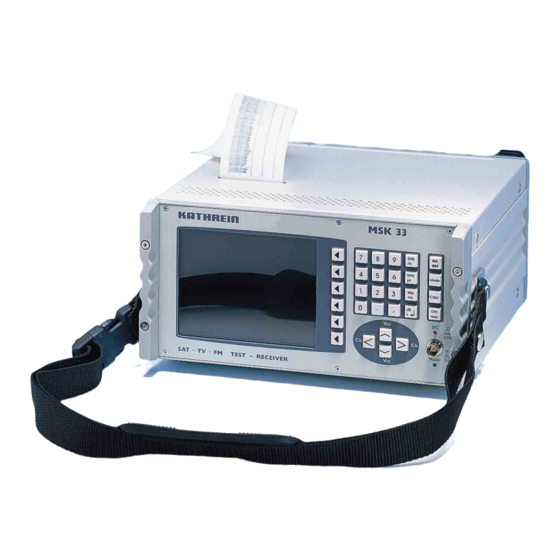
- Page 1 Operating manual Sat/TV/FM Test Receiver MSK 33 Software version 8.3 December 2002...
-
Page 3: Preface
Publications, copies and print-outs as well as electrical distribution of this manual in full or in part is only allowed with written authorisation from the Kathrein-Werke KG. All product names and trademarks used in this manual are the property of the rele-... -
Page 4: Table Of Contents
Contents PREFACE... 3 IMPORTANT NOTES ... 12 Validity of this manual... 12 General safety information ... 12 Explanation of symbols... 12 SAFETY INSTRUCTIONS ... 13 Connections... 13 Proper use ... 13 Mechanical loadbearing capacity ... 13 FUNCTIONS... 14 Functions ... 14 Functions overview... - Page 5 Contents RF output ... 23 Headphone connection... 23 Modem / RS232 interface... 23 Scart socket ... 23 Socket TS PARALLEL (optional)... 23 MEASUREMENT POSSIBILITIES... 24 Level measurement ... 24 Maximal input level ... 24 SAT OPERATION ... 25 Sat menu ... 25 Entry of the transponder frequency from 00,000 MHz to16,000 MHz...
- Page 6 Contents V-SEC menu... 36 Entering the hex numbers ... 36 Sending a V-SEC command (TX) ... 36 Initial ANALOG-menu ... 37 Calling up the sound subcarrier menu... 37 Level-dependent acoustic signal ... 37 Level measurement ANALOGUE... 37 Second ANLAOG menu ... 38 Selecting the colour standards PAL, SECAM and NTSC ...
- Page 7 Contents TV DIGITAL menu ... 47 DVB-C... 47 Level-dependent acoustic signal ... 47 Selecting demodulation for DVB-C measurement ... 47 Symbol rate entry ... 47 DVB-T (optional)... 48 Level-dependent acoustic signal ... 48 Selecting channel bandwidths... 48 MPEG decoder menu (OPTION)... 48 RETURN PATH IF MENU ...
- Page 8 Contents SETTING MENU... 58 Modem menu... 58 Screen menu ... 58 SYSTEM menu... 58 Measuring unit ... 58 Entering the level offset ... 58 SCREEN MENU ... 59 Setting the brightness... 59 Setting the contrast... 59 Setting the colour saturation... 59 Setting the background light ...
- Page 9 Contents Position and triggering of the DiSEqC signal ... 68 SPECTRUM MENU ... 69 Level measurement of analogue signals... 69 Level measurement of digital signals ... 69 Selecting the spectrum representation... 70 ANALOG marker ... 70 DIGITAL marker ... 70 C/N measurement of analogue signals in Sat operation...
- Page 10 Command overview data byte ... 100 DiSEqC commands for Kathrein matrices... 100 Command for Kathrein matrix 9xx-series ... 100 Command for Kathrein matrix EXR 20 ... 100 Command for Kathrein matrix EXR 22 ... 100 Channel tables... 101 Channel and frequency table standard B/G (frequency in MHz)... 101...
- Page 11 Contents Channel and frequency table standard D/K (frequency in MHz)... 103 Channel and frequency table standard I (frequency in MHz)... 104 Channel and frequency table standard M/N (frequency in MHz) ... 105 Channel and frequency table standard M/N(frequency in MHz) ... 106 Special channels ...
-
Page 12: Important Notes
Important Notes Important Notes Validity of this manual This manual is valid for the MSK 33, order no.: 208 299, 208 302, 208 303, 208 305, 208 209, 208 311, 208 312, 208 313, 208 314, 208 316, 208 318, 208 319, 208 321, 208 322, 208 325, 208 326, 217 10001, 217 10002, 217 10003, 217 10004. -
Page 13: Safety Instructions
Safety Instructions Safety Instructions Observe the VDE safety regulations! Observe the admissible maximum level when feeding signals. A maximum of 0.5 watts of total power may be applied to the RF input. Only fuses which have the same cut out characteristic may be used. The unit is also live when disconnected. -
Page 14: Functions
Functions Functions Functions With Sat/TV/FM signal meter MSK 33, detailed quality assessment of DVB-C, DVB-T and DVB-S signals may be carried out along with level measurements of analogue and digital TV and Sat reception signals. The unit is constructed in modular technology, so future function extensions by means of plug-in cards are easily possible. -
Page 15: Functions Overview
Functions Functions overview Function Digital Mains and battery operation External battery supply Picture assessment DVB level measurement (DVB-S/C/T) Level measurement by frequency entry Level measurement by channel entry IF level measurement (4…80 MHz)* Constellation analysis Level-dependent acous- tic signal Loudspeaker for sound control Multi-standard (B/G, D/K, I, L, M, M jap) -
Page 16: Displays, Operating Elements And Connections
Displays, Operating Elements and Connections Displays, Operating Elements and Connections Front panel All operating elements, the display screen and the RF input are located on the front panel of the MSK 33. TFT display screen Numerical entry field Vol- and Vol+: Volume adjustment Ch- and Ch+: Channel switching For some unit functions, the four functions function as cursors. -
Page 17: Rear Panel
Displays, Operating Elements and Connections Rear panel The interfaces, output and input sockets and the mains connection are located on the rear panel of the MSK Mains connection Mains switch DC socket (Option / XLR-socket) for the operation of an external DC voltage of 10.8...14 V and for charging the accumulator Headphone connection 3.5 mm jack plug for stereo headphones... -
Page 18: Observing Angle Of The On Screen Display
Displays, Operating Elements and Connections Observing angle of the on screen display The viewpoint of the TFT display is chosen so that a picture assessment is seen from an angle of up to 15° from the top and up to 30° from below . The observing angle from the side is ±45°. -
Page 19: Operating Concept
Operating Concept Operating Concept The screen Frequently recurring softkeys With this softkey, you always return to the previous menu. Level-dependent acoustic tracking signal The acoustic tracking signal is generated in the function, „level beep.“ The pitch of the sound is proportionate with the received signal level. This allows optimal alignment of the receiving antenna to a transmitter. -
Page 20: General Information For Operation
Operating Concept General information for operation The following explanations are important for understanding the logical menu structure of the MSK 33. Please take time carefully reading the following paragraphs. Menu selection The MSK 33 is operated via the buttons and various displayed screen menus. The selection of the menu items are effected by the softkey buttons on the right of the display. -
Page 21: Operation
To avoid heat build-up, the openings for the ventilators and the ventilation slots on the top of the unit must always be free. Use the leather case MZK 15 from Kathrein for mobile use. Mains voltage / mains switch The unit can be operated on AC current networks of 110...240 V with a network frequency of 50...400 Hz. -
Page 22: Accumulator And Battery Operation
Accumulator and Battery Operation Accumulator and Battery Operation Accumulator operation The accumulator of the MSK 33 is not charged in delivery status and must be charged before initial operation. To do so, connect the unit with the mains, and switch on the power supply with the mains switch on the front panel of the unit. When the green LED on the front panel lights up, the accumulator is charged. -
Page 23: Connections
Connections Connections RF output The receiving signal is fed into the RF input socket (BNC socket). It delivers also the remote power feeding voltage. The remote power feeding voltage is adjustable and disconnectable from 10 to 20V. For control, the red LED over the RF input socket lights up when the LNB voltage is switched on. -
Page 24: Measurement Possibilities
Measurement Possibilities Measurement Possibilities Level measurement The MSK 33 is designed for the level measurements on receiving systems in the measuring range of 30 dBµV to 130 dBµV. The level measurement is automati- cally carried out after connecting the unit and setting a frequency and is displayed on the display screen. -
Page 25: Sat Operation
Sat Operation Sat Operation Sat menu analog Entry of the transponder frequency from 00000 MHz to16000 MHz The field lights up yellow, as soon as a softkey is pressed. Now, the transponder frequency can be entered-in using the numerical buttons „0-9“ and „MHz“ or changed with the cursor buttons, ◄►. -
Page 26: Setting Of The Lnb Voltage Supply
Sat Operation Setting of the LNB voltage supply: LNB: U= 14,0V I=181mA LNB control menu Selecting the LO frequency Press the LNB-CONTROL button in the Sat menu. With the button LO, you can request nine preset LO frequencies. Set LO1 (09750) in the field. With the BACK button, open the Sat menu again. -
Page 27: Scan
Sat Operation SCAN With the function SCAN, satellites can be searched for, whose transponder fre- quencies are not known. Here, the frequency range of 920 to 2150 is continuously scanned for the receiving signals. If the receiving signals are available, the recep- tion level is displayed on the screen as a bar diagram. -
Page 28: Lnb Control Menu
Sat Operation LNB control menu In the LNB control menu, the LNB supply voltage, 22 kHz control signal, DiSEqC and VSEC commands can be set. The voltage or signals are available on the RF socket. If the LNB supply voltage is activated, the red LED above the RF sockets lights up. -
Page 29: Checking The Lnb Supply Voltage Of A Satellite Receiver
Sat Operation Checking the LNB supply voltage of a satellite receiver Connect the satellite receiver (IF input) with the MSK 33 (RF input socket). Switch the supply voltage of the MSK 33 OFF and the voltage of the receiver ON. You can now read the output voltage on the screen. -
Page 30: Diseqc Menu
Sat Operation DiSEqC menu With the MSK 33, DiSEqC commands can be sent (TX) and received (RX). The code words –framing, address, command, data- are displayed on the screen in the upper RX display field for received DiSEqC commands and in the lower TX display field for transmitted DiSEqC commands. -
Page 31: Submenu For Entering Diseqc Commands
Sat Operation Submenu for entering DiSEqC commands This submenu is called up by pressing the button „tx input“ in the DiSEqC menu. Refer to the technical appendix of this operating manual for an overview of the DiSEqC commands. TX display field Display field A Display field B Entry... -
Page 32: Entering And Transmitting A Diseqc Command
Sat Operation Example Entering and transmitting a DiSEqC command Simple DiSEqC By repeatedly pressing the second softkey button, you access the Simple DiSEqC menu. Also here, respective commands can be sent. Simple DiSEqC offers two control possibilities: a continuous 22 kHz tone burst and an uninterrupted 22 kHz data burst. -
Page 33: Ufomicro Diseqc Menu
UFOmicro DiSEqC menu General information In the UFOmicro mode, one or various head stations EXU 544 in a Kathrein in- house system can be tested. The test can be carried with or without a KATHREIN satellite receiver from the 400 series or higher. -
Page 34: Receiver Field
Sat Operation Receiver field Rec adr r-zf t0 t1 t2 st >02<244 1200 20 12 4 The receiver 2 is registered in the head station with the address 244. The remote IF is 1200 MHz. The collision pages are t0 = 20 ms, t1 = 12 ms and t2 = 4 ms. The status of the re- ceiver 2 is „registered.“... -
Page 35: Installation Of A Ufoµ Unit Exu 544 In Conjunction With The Msk 33
In this arrangement, the MSK 33 is connected to the output of the head station and simulates up to 12 Kathrein receivers. A registration of the MSK 33 receiver (de- pending on the number of EXU 544 in the system segment) should be carried out in the head stations. -
Page 36: V-Sec Menu
Sat Operation V-SEC menu By repeatedly pressing the second softkey, you access the V-SEC menu. V-SEC simply offers the possibility to send a data item. It gives no reply. ---------VSEC-------- VSEC----------------- TX:<- BB Entering the hex numbers Call up a submenu by entering in the hex numbers. -
Page 37: Initial Analog-Menu
Sat Operation Initial ANALOG-menu ---SAT MEASURE ALL--- min/max 55.5/56.0dbµV ------------- ><11208.00MHz A56.0dBµV received signal level. With it, it is possible to optimally align the receiving antenna to a transmitter. In this menu, the receiving frequency can be changed using the cursor buttons, ◄►. -
Page 38: Second Anlaog Menu
Sat Operation Second ANLAOG menu Switch-over of the video polarity between positive and negative. A „ “ stands for positive video signal. A„ “ stands for negative video signal. Return to the first submenu ANALOG. The Sat menu is called Selecting the colour standards PAL, SECAM and NTSC Selecting the video hub... -
Page 39: Sat Subcarrier Menu
Sat Operation Sat subcarrier menu Audio carrier frequency Display of the set audio carriers. The audio carriers can be changed from 5.8 MHz to 8.64 MHz in 10 kHz increments. Use the cursor buttons, ◄►, to change the value. Audio carrier setting Thirteen different preset audio carrier frequencies can be selected (refer to audio carrier table). -
Page 40: Audio Carrier Tables For The Satellite Reception
Sat Operation Audio carrier tables for the satellite reception The reception parameters – audio frequency, audio carrier bandwidth, de- emphasis – are linked to each other by the software, so no operation error can re- sult from calling up an incorrect parameter. Audio carrier table for reception type: MODUS MONO w... -
Page 41: Digital Measurements
Digital Measurements Digital Measurements SAT DIGITAL menu ---SAT MEASURE ALL---- min/max: 38.0/65.0 dBµV ><1832.50MHz D65.0 dBµV Convulsion code for Sat measurement With this button, the convulsion code is set for demodulating the QPSK signals from 1/2 to 8/9. The setting is adopted for the constellation analysis. ➧... -
Page 42: Level Measurement Digital (Min./Max. Levels)
Digital Measurements Level measurement DIGITAL (Min./Max. levels) Calls up the level measurement DIGITAL as well as MIN./MAX. In this function, minimal and maximal levels are measured. This function serves for monitoring the measurement points to level fluctuations. Even after exiting the menu, the MSK 33 stays set to DIGITAL reception. -
Page 43: Tv Operation
TV Operation TV Operation TV menu C10 210.25MHz A65.0dBµV Receiving frequency is optimally set Frequency is not optimally tuned Entering in a channel This field lights up yellow, as soon as the softkey is pressed. The channel can be < > entered with two digits with the numerical buttons, „0...9“... -
Page 44: Tv Control Menu
TV Operation TV control menu 22 kHz control signal LNB: U= 0.0 V I= 0 mA voltage value can be entered in with the buttons, 0...9, or changed in the range from 10 V to 20 V with the cursor buttons, ◄►. By pressing the button once more, the LNB supply voltage is disconnected again. -
Page 45: Analogue Menu
TV Operation Analogue menu The given audio carrier frequencies are based on the video audio carrier Standard M (Japan) Selecting the audio carriers By pressing the button, the MSK 33 can be set to the following reception types: • Audio carrier 1 (sc1) •... -
Page 46: Measuring Audio Carrier Spacing
TV Operation - Minimal and maximal levels (min./max.) – Level measurement ANALOGUE The respective following displays appear on the screen, when the button, „meas- ure“ is pressed. Measuring audio carrier spacing ----TV MEASURE ALL --- SC1/SC2:-13.5/-19.5dB Measuring the Nicam audio carrier spacing and bit error rate NICAM: -18.5 dB 5.6E-06... -
Page 47: Tv Digital Menu
TV Operation TV DIGITAL menu DVB-C ----TV MEASURE ALL---- min/max: 38.0/65.0 dBµV S32 394.00MHz D65.0dBµV Selecting demodulation for DVB-C measurement With this button, the type of demodulation, QAM64, QAM128 or DOCSIS QAM64 QAM64 (Softkey designation = DOC64 Mode) is selected. The setting is taken over for the Mode ➧... -
Page 48: Dvb-T (Optional)
TV Operation DVB-T (optional) ----TV MEASURE ALL---- min/max: 38.0/65.0 dBµV C21 474.00MHz D65.0dBµV For correct level measurement of digital signals, you can choose between 3 chan- nel bandwidths (6, 7 and 8 MHz). This programming is taken over for the constella- chBW 8MHz ➧... -
Page 49: Return Path If Menu
Return Path IF Menu Return Path IF Menu Return path IF menu TV-IF38.90MHz A65.0dBµV RP 22.40 MHz A 65.0dBµV ANALOG Menu analog > MEASURE DIGITAL menu digit. DVB-C> MEASURE IF CONTROL menu (RP-CONTROL*) In this menu, all remotely controlled parameters, such as remote feeding voltage, IF (RP) 22 kHz, DiSEqC, tone burst (simple DiSEqC), V-SEC, can be set (for further infor- mation, refer to TV menu). -
Page 50: Analog Menu
Return Path IF Menu ANALOG menu In this menu, all settings for the measurement of the analogue IF signal with the frequency of 38.9 MHz can be made. Audio carrier table for IF reception The given audio carrier frequencies are based on the respective video-audio carrier spacing. The video carrier frequency is 38.9 MHz without the return path option for each standard and can not be changed. -
Page 51: Carrying Out Measurements
Return Path IF Menu Carrying out measurements By pressing this button, the MSK 33 is set to analogue reception and measures the following values: - Audio carrier spacing from TT1 (sc1) and TT2 (sc2) - Nicam audio carrier spacing (if available) - Nicam bit error rate (BER) - Minimal and maximal level (min./max.) Level measurement ANALOGUE... -
Page 52: If Rp Digital Menu
IF RP DIGITAL Menu IF RP DIGITAL Menu DVB-C --- RP MEASURE ALL ---- min/max: 38.0/65.0 dBµV 48.25MHz D65.0 dBµV Selecting demodulation for DVB-C measurement With this button, the type of demodulation, QAM64, QAM128 r DOCSIS QAM64 QAM64 (Softkey designation = DOC64 mode), can be selected. The setting is taken over mode ➧... -
Page 53: Radio Operation
Radio Operation Radio Operation RADIO menu RADIO CONTROL menu In this menu, all remotely controlled parameters such as remote feed voltage, 22 kHz, DiSEqC, tone burst (Simple DiSEqC) and V-SEC can be set. ANALOG menu In this menu, min./max. level measurements are possible and the „level beep“ can be activated. -
Page 54: Measuring The Min/Max Level
Radio Operation Measuring the min/max level ----FM MEASURE ALL --- min/max: 61.5/64.5dBµV Measuring the current level As long as this measurement function is called up, the MSK 33 measures the minimal level and the maximal level. This measurement function serves for monitoring the check points for level fluctuations. -
Page 55: Av Menu
AV Menu AV Menu With the third softkey from the top, the following four operating types can be set on the Scart socket. Decoder operation In this operating type, a decoder for decoding coded signals, e.g. Premiere, can be CVBS connected to the Scart socket. -
Page 56: Breaking Voltage
AV Menu Breaking voltage This function serves for supplying a breaking voltage on the Scart socket, in order to control external units. By pressing this button, the breaking voltage can be switched ON or OFF. RGB operation With this softkey, a RGB signal is available on the Scart socket or a RGB signal can be fed-in at the Scart socket. -
Page 57: Mpeg Decoder Menu (Optional)
MPEG Decoder Menu (Optional) MPEG Decoder Menu (Optional) ---- PAT (08) --00-- >ZDF 3sat KiKa Phoenix Video-PID: 1040 MPEG 2V Audio-PID: 1042 MPEG 2A Norm: dig. television Status:running ---- PAT (08) --00-- >ZDF With the arrow softkeys, the desired programme can be selected. Video-PID:1040 MPEG 2V Audio-PID:1042 MPEG 2A The button „show PAT“... -
Page 58: Setting Menu
Setting Menu Setting Menu Setting In this menu, brightness, contrast, colour and background light of this TFT screen are set. SYSTEM menu In this menu, date and time as well as the software version and the unit number are given out. Measuring unit unit Softkey for the switch-over of dBµV to dBmV and vice versa. -
Page 59: Screen Menu
Screen Menu Screen Menu Setting the colour saturation Pressing this button allows the colour saturation to be set with the cursor buttons, ◄►. The set value is automatically saved. Setting the background light Pressing this button allows the background light to be set with the cursor buttons, ◄►. -
Page 60: System Menu
System Menu System Menu -SOFTWARE-VERSIONS- ---- operating system FPGA firmware = V8.1 S1 =V2.1 00612 TIME: 14:31:26 DATE: 14.11.01 Setting the time After pressing this softkey, the field „TIME“ lights up yellow and the time field flashes. The time can now be entered in with the numerical buttons. Click button With this button, a peep tone for the keyboard can be generated and switched off. -
Page 61: Copy Menu
Copy Menu Copy Menu Saving and calling up unit settings Saving the unit settings One hundred memory positions (00-99) are available for saving the settings of the unit. First, select the unit setting, which is to be saved, and then call up the COPY menu. -
Page 62: Printing Out All Measurements In Tv Mode
Copy Menu Printing the measurement results By pressing the softkey, the current measurement result along with the date and time are printed out. If the function, „measure,“ is called up in the TV, Sat or FM menu, all the meas- urements are printed out. -
Page 63: Mode Menu
Mode Menu Mode Menu BACK with MODE key Calls up the TEXT menu (refer to the appropriate section). TEXT Calls up the SCOPE menu (option, refer to the appropriate section). SCOPE Exit the mode menu by pressing the button „MODE“ once more. AUTO AUTO MEASURE... -
Page 64: Text Menu
Text Menu Menu Text Videotext Enlarging the videotext page By pressing the button, the upper or lower area of the text page can be enlarged. Original videotext size By pressing this button, the function LARGE is deactivated. The page appears in the original size. -
Page 65: Scope Menu
Scope Menu Scope Menu Video scope menu Horizontal zoom – Reducing the video signal By pressing this button, the video signal can be reduced on the screen. Eight zoom stages are available. Each time the button is pressed, the zoom switches to the next lower stage. -
Page 66: Measurement Of The Amplitude Of The Video Signal
Scope Menu The following values are displayed on the screen: With this softkey, the input loss can be changed to +4 dB and +8 dB. This in- rflev creases the measurement dynamic. (Be careful of intermodulation!). +0dB Number of the measuring cycles with averaging (1 to 5 measuring cycles). sample Measurement of the amplitude of the video signal Measurement of video signals via the AV socket (SCART) -
Page 67: Audio Scope
Audio Scope Audio Scope Reducing time / unit With this function, the audio signal can be lengthened on the display. Eight time- - time stages are available. The unit switches accordingly to the next lower time stage, when the button is pressed once more. If the softkey field no longer changes col- our, the lowest time stage is reached. -
Page 68: Diseqc Scope
DiSEqC Scope DiSEqC Scope With this function, the DiSEqC signal can be stretched on the display. Eight control - time time-stages are available. The unit switches accordingly to the next lowest stage, once the button is pressed once more. If the softkey field no longer changes col- our, the lowest stage is reached. -
Page 69: Spectrum Menu
Spectral Menu Mark 208.75 A 52.5dBµV Anzeige der Frequenz und des Pegels des gelbenMarkers C: 203.25MHz 20MHz/Div A 64.0dBµV C-M: 11.5dB Level measurement of analogue signals By calling up the spectrum analysis from the analogue TV or Sat menu, the ana- logue level on the white marker is measured and displayed on the screen in the lower line. -
Page 70: Selecting The Spectrum Representation
Spectral Menu Selecting the spectrum representation By pressing this button, the represented frequency range can be defined per scale unit. The following settings are possible: Setting SAT operation Span/DIV large 100 MHz 8 MHz 20 MHz 1 MHz med. small 5 MHz 1 MHz full... -
Page 71: C/N Measurement Of Digital Signals In Sat Operation
Spectral Menu C/N measurement of digital signals in Sat operation The spectrum menu is opened in the setting, digital reception. The yellow marker marker is moved between two carriers or in frequency gaps. The C/N measurement is car- ried out in medium or small span. dig. -
Page 72: Const Menu
Const Menu Const Menu The function constellation diagram can be called up in the operation types, SAT (DVB-S), TV (DVB-C and DVB-T), TV-IF or return path (DVB-C). Operating the constellation functions is principally the same in the various operating types. The differences are described below. -
Page 73: Measurement Of Signal Noise Ratio (Snr)
Const Menu rate, which the MSK 33 can measure, is 1.0 e-8. If the rate is lower than these values, the display of the BER jumps to zero „0“ (no longer bit error). The highest BER, which can be displayed, is 1 e-2. Generally, it can be assumed, that picture disturbance can occur by a BER of ca. -
Page 74: Selecting The Symbol Rate (Symbol-Clock)
Const Menu Selecting the symbol rate (symbol-clock) 27.500 27.5 MS, 20 MS, 24.5 MS or 22 MS – or entry between 0.5…32 MS. SR 1 ► Selecting the code rate (1/2, 2/3, 3/4, 4/5, 5/6, 6/7, 7/8, 8/9) CR ► Inverting /not inverting a constellation diagram Invers Display the status of the frequency spectrums or the constellation diagram. -
Page 75: Examples For Qpsk Constellation Diagrams
Const Menu Examples for QPSK constellation diagrams QPSK signal without faults QPSK signal with intermodulation noise QPSK signal with phase noise (LNC) QPSK signal with superposed broadband noise. Possible cause: Defective amplifier or high cable loss. QPSK signal with amplitude hum of an amplifier... -
Page 76: Constellation Diagram For Qam (Dvb-C)
Const Menu Constellation diagram for QAM (DVB-C) pressing the appropriate softkey. The buttons are represented in yellow for acti- vated functions. Buttons, which have multi-functions, are indicated with an arrow and are represented in yellow as well. By repeatedly pressing the same button, dif- ferent parameters can be called up and displayed. -
Page 77: Frontend Locked
Const Menu Frontend locked If the receiving part of the MSK 33 is locked on the carrier frequency of the re- ceived signal, the display, „Frontend locked“ appears on the screen. If a represen- tation of the constellation diagram is not possible, the display „not locked“ is dis- played. -
Page 78: Examples For Qam Constellation Diagram
Const Menu Examples for QAM constellation diagram The following examples show possible errors and their representation in the constellation diagram. 64 QAM signal without faults 64 QAM signal with low broadband noise. Possible cause: Bad amplifier or to small of input level on an amplifier in the transmission line. - Page 79 Const Menu 64 QAM Signal with phase noise of a converter 64 QAM signal with I/Q phase error of a converter 64 QAM signal with amplitude hum of an amplifier 64 QAM signal with signal I/Q amplitude error of the converter Unsynchronised demodulator- no input signal.
-
Page 80: Dvb-T
DVB-T DVB-T Constellation diagram DVB-T (optional) For the terrestrial digital transmission of television signals (DVB-T), the modulation type COFDM (Orthogonal Frequency Division Multiplex) is used. In 2k mode, 1705 carries and in 8k mode 6817 carriers either QPSK-, QAM16- or QAM64 are modulated. -
Page 81: Hierarchy
DVB-T Hierarchy Meaning: Two carriers streams are simultaneously transmitted and the transport stream with the higher priority is QPSK modulated. There are four hierarchy steps (0, 1, 2 and 4). Hierarchy = 0 menus, that the signal is not hierarchy modulated. Hierarchy = 1 means, that the signal is hierarchically modulated. -
Page 82: Code Rate
DVB-T Code rate Display the measured code rate ½, 2/3, ¾, 5/6 or 7/8. Guard Displays the ratio between guard interval and symbol time 1/4, 1/8, 1/16 or 1/32. Invers The display of the condition of the frequency spectrum or the constellation diagram. Setting occurs automatically. -
Page 83: Impulse Response Representation (Echo Representation) (Optional)
DVB-T Press this button upper left-hand represented and pressing the button diagram is represented. Impulse response representation (Echo representation) (optional) Echo representation: marker display in µs Echo representation: marker display in km zoom to enlarge the constellation diagram. The on► section of the constellation diagram is now allows a closer look of signal symbols. -
Page 84: Broadband Cable Analysis Measuring System Msk 33 / Mvg
Broadband Cable Analysis Measuring System MSK 33 / Broadband Cable Analysis Measuring System MSK 33 / MVG Measuring principle MVG10 The broadband cable analysis system consists of the antenna measuring instrument MSK 33 (including return path option) and the signal generator MVG 10. Both units function in the frequency range from 4.0 MHz to 860 MHz. - Page 85 Broadband Cable Analysis Measuring System MSK 33 / TRACK. MVG10 ☞ <> mark reflv ► First select the reception frequency in the reception menu TV or RP. With this, the MVG 10 begins to „sweep.“ mode with the second softkey. In this mode, all MVG signals in respect to the frequency and level are recorded from the starting frequency up to the end...
-
Page 86: Comfortable Upstream 4.0
Broadband Cable Analysis Measuring System MSK 33 / Comfortable upstream 4.0…80 MHz and Downstream 47…860 MHz measurement MSK33 Receiver (1) with return path amplifiers ext FBAS Graphic MVG10 (2) Signal wobbel- generator Upstream measurement Downstream measurement Preparation First, the signal generator with external RGB modulation must be stored on the memory posi- tion „0“... - Page 87 Broadband Cable Analysis Measuring System MSK 33 / It is possible to transmit the received spectrum on the head station or a FBAS sig- nal of an external unit (camera, head station computer etc.) via the MVG 10 (2) on free CATV channels.
-
Page 88: Auto Measure
Auto Measure Auto Measure measurement point !after start is point +1 list rcl. ---setting--- 1 >85< NO SETTINGS 2 02 3 03 4 04 5 05 6 06 7 07 8 08 9 09 Display of the check point measurement point >02< after start is point+1 point Display of the entry field for the respective measurement task... -
Page 89: Interfaces
Interfaces Interfaces Modem / RS 232 interface The serial interface RS 232 is executed as 25-pin SUB-D socket. it is required for controlling the MSK 33 via mode, or PC. Connection cable for modem / RS 232 In order for he MSK 33 to be able to be remotely controlled via the RS 232, a con- nection between the signal meter and the PC or external modem must be estab- lished. -
Page 90: Modem/Rs232 Menu
Interfaces Modem/RS232 menu Setting baud rate The field lights up yellow, as soon as the softkey is pressed. Afterwards, the inter- rate face speed from 2400 to 115200 baud (each 8 bits / no parity /no stop bit) can be set with the aid of the cursor buttons, „<„... -
Page 91: Code (Password)
Interfaces After pressing this button, the MSK 33 is reset to the factory setting. Code (Password) Here, the currently valid password can be read, which must be known by the used for the remote request or control of the MSK 33. The password can only be changed in active modem operation. -
Page 92: Requesting Help
Interfaces Requesting help In the TTY mode, the list of the available commands can be requested with the question mark. In this list, the first three letters are capitalised, which should indi- cate that it concerns a key abbreviation. The entry of the first three characters the command (occurs with RETURN) is here sufficient to trigger the respective com- mand. - Page 93 Interfaces Note: Alt + S + cipher is in general base on functions of the respective terminal programme. The picture of the left shows an example of a pulldown menu. On the left of the picture, there is a frame for entering parameter- afflicted commands, which repre- sents a summary of current unit setting.
-
Page 94: List Of The Command Abbreviations
Interfaces List of the command abbreviations General commands Switch over from the ANSI terminal (menu-orientated operation according to the SAA standard) into the TTY terminal mode (line-oriented operation). Switch over from the TTY terminal mode (line-orientated operation) to the NASI terminal mode (menu- orientated operation according to SAA standard. - Page 95 Interfaces Loading and saving predefined settings Saving of the current unit setting under a user-defined programme position number from 00-99. Entry: STU <RET> STU 34 <RET> Loading the setting by the identified programme position number 00-99. Entry: LDU <RET> LDU 34 <RET> Action: You are asked for the programme position, under which the unit set- ting should be saved.
-
Page 96: Maintenance, Storage And Customer Service
Unit calibration The calibration interval depends on the use and demand, and should be made every 1 and 2 years. The calibration can be carried out by the KATHREIN cus- tomer service centre (see below). Exterior cleaning The exterior of the unit is cleaned when needed with a soft, not fibrous dusting rag or brush. -
Page 97: Printer Paper-Exchanging The Ribbon
Maintenance, Storage and Customer Service Printer paper-exchanging the ribbon Before opening the unit, disconnect the supply voltage. Paper exchange Remove the housing cover of the MSK 33. The housing cover is attached with four screws. After opening the unit, take out the axle with the empty paper roll. Insert the beginning of the paper of the new roll into the paper slot of the printer (between plastic and metal), than press down the button „LF - linefeed“... -
Page 98: Technical Appendix
Technical Appendix Technical Appendix Overview of DiSEqC commands Command overview framing byte Hex-byte Command overview address byte Hex-byte Description Commando from master, one time transmission Commando from master, repeated transmission Commando from master, answer expected, first transmission Commando from master, answer expected, repeated transmission Answer from slave, „OK“, no error detected Answer from slave, commando is not supported by slave Answer from slave, parity error is detected... -
Page 99: Command Overview Command Byte
In the MSK 33, two different DiSEqC types have integrated. DiSEqC 1.0: With this system, DiSEqC commands can be sent but not received. DiSEqC 2.0: With this system, DiSEqC commands can be sent and received (highlighted in grey in the table). Bold com- mands are preferably used for Kathrein switching matrices. Number... -
Page 100: Command Overview Data Byte
These commands are stored under the recall addresses 80...95 at the factory. Command for Kathrein matrix 9xx-series Range DiSEqC- command Range DiSEqC- command Command for Kathrein matrix EXR 20 Command for Kathrein matrix EXR 22 Switch position H/V Switch position LNB POS. A (Satellite1) Low-band Vert. Hor. -
Page 101: Channel Tables
Technical Appendix Channel tables Channel and frequency table standard B/G (frequency in MHz) The table show the channel, display MSK 33 and frequency. VHF-CCIR Pilot freq. USB/OSB Digital Digital UHF-CCIR 80.15 48.25 55.25 62.25 175.25 182.25 189.25 196.25 203.25 210.25 217.25 224.25 53.75... -
Page 102: Channel And Frequency Table Standard L(Frequency In Mhz)
Technical Appendix Channel and frequency table standard L(frequency in MHz) The table show the channel, display MSK 33 and frequency. *LC1 80.75 55.75 60.50 63.75 176.00 184.00 192.00 200.00 208.00 216.00 308.75 861.75 175.25 183.25 191.25 199.25 207.25 215.25 223.25 Special channels 471.25 671.25... -
Page 103: Channel And Frequency Table Standard D/K (Frequency In Mhz)
Technical Appendix Channel and frequency table standard D/K (frequency in MHz) The table show the channel, display MSK 33 and frequency. R-II R-III R-IV R-VI R-VII R-VIII R-IX R-XI R-XII 49.75 59.75 77.25 85.25 175.25 183.25 191.25 199.25 207.25 215.25 223.25 50.00 60.00... -
Page 104: Channel And Frequency Table Standard I (Frequency In Mhz)
Technical Appendix Channel and frequency table standard I (frequency in MHz) The table show the channel, display MSK 33 and frequency. 45.75 53.75 61.75 175.25 183.25 191.25 199.25 207.25 215.25 223.25 231.25 239.25 247.45 50.00 60.00 70.00 75.00 80.00 90.00 175.00 Special channels 471.25... -
Page 105: Channel And Frequency Table Standard M/N (Frequency In Mhz)
Technical Appendix Channel and frequency table standard M/N (frequency in MHz) The table show the channel, display MSK 33 and frequency. C72.00 C55.25 C61.25 C67.25 C77.25 C83.25 C175.25 C181.25 C187.25 C193.25 C199.25 C205.25 C211.25 471.25 669.25 477.25 675.25 483.25 681.25 489.25 687.25 495.25... -
Page 106: Channel And Frequency Table Standard M/N(Frequency In Mhz)
Technical Appendix Channel and frequency table standard M/N(frequency in MHz) The table show the channel, display MSK 33 and frequency. Special channels A-5 95 959 S01 91.25 A 4 96 97.25 A-3 97 103.25 A-2 98 109.25 A-1 99 115.25 A 14 121.25 B 15... -
Page 107: Technical Data
Technical Data Technical Data Technical data Power supply Mains operation Accumulator operation Power draw DCP Power draw ACP Dimensions Safety standards Screen Temperature range Storage and operating temperature Frequency range Channel plan Frequency setting Test error /level Slope RF input RF input factor Level measurement range Measurement bandwidth... - Page 108 Technical Data Nicam –audio - bit error rate Video output (Scart) Video output (BNC/option) LNB supply voltage LNB control SAT analogue measurements TV analogue measurements DVB-S measurements QPSK DVB-C measurements QAM64, QAM128, QAM256 DVB-T measurements (COFDM) 2k / 8k mode Weight Standard B/G Standard D/K...
-
Page 109: Scope Of Delivery
Technical Data Scope of delivery 1 Mains cable 1 Measurement cable- BNC-connector - BNC- connector - 1 Adapter - BNC- socket - F-socket 1 Adapter - BNC- socket - F- connector - 1 Adapter - BNC- socket - IEC connector - 1 Adapter - BNC- socket - IEC socket 1 Operating manual Accessories... -
Page 110: Assignment Of Rs232 Socket
Technical Data Assignment of RS232 socket Connection Signal Note S-GND... -
Page 111: Assignment Of Socket Ts Parallel (Optional)
Technical Data Assignment of socket TS PARALLEL (optional) TS PARALLEL Connection Signal Abbreviation Clock for data item CLOCK A Earth Data bit 7 (high-value data DATA BIT 7 A (MSB) bit) Data bit 6 DATA BIT 6 A Data bit 5 DATA BIT 5 A Data bit 4 DATA BIT 4 A... -
Page 112: Unit Variants
Technical Data Unit variants MSK 33/G Integrated graphic card Spectrum analyser S/N measurement (weighted) Digital video-, audio- and DiSEqC- oscilloscope MSK 33/Q Integrated graphic card and digital card (DVB-C-S card) Coloured representation of the constellation analysis for QAM and QPSK signals Measurement of bit error rate for QAM and QPSK signals Display of modulation error rate (MER) for QAM Display of signal-to-noise ration SNR for QPSK... -
Page 113: Downloading New Msk33 Operating Software
Downloading New MSK33 Operating Software Downloading New MSK33 Operating Software General notes: Observe the bold lines. The non-bold notes can only help you solve a problem in cases of error. <RET> means to trigger the command with RETURN on the termi- nal programme. - Page 114 Notice Notice...
- Page 115 Notice...
- Page 116 KATHREIN-Werke KG Telefon (0 80 31) 18 40 Fax (0 80 31) 18 43 06 Anton-Kathrein-Straße 1-3 Postfach 10 04 44 D-83004 Rosenheim...
Need help?
Do you have a question about the 9986492 and is the answer not in the manual?
Questions and answers