Table of Contents
Advertisement
Quick Links
Advertisement
Table of Contents

Subscribe to Our Youtube Channel
Related Manuals for Kathrein UFS 710si


Summary of Contents for Kathrein UFS 710si
- Page 1 Operating manual - englisch - DVB Satellite Receiver UFS 710si/710sw...
-
Page 2: Preface
We wish you good reception and much pleasure using your new DVB satellite receiver. Your KATHREIN Team DISPOSAL INSTRUCTIONS Electronic equipment is not domestic waste - in accordance with directive 2002/96/EC OF THE EUROPEAN PARLIAMENT AND THE COUNCIL dated 27 and electronic appliances, it must be disposed of properly. -
Page 3: Important Information
Audio MPEG Inc. and Societa‘ Italiana per lo sviluppo dell‘elettronica, S.I.SV.EL, S.P.A, have granted KATHREIN-Werke KG rights of use which are subject to certain restrictions. These restrictions must also be observed by you as a customer. -
Page 4: Table Of Contents
... 2 PREFACE IMPORTANT INFORMATION ... 4 CONTENTS SAFETY INSTRUCTIONS - IMPORTANT NOTES RECEIVER FEATURES/SCOPE OF SUPPLY CONTROLS, DISPLAYS AND CONNECTIONS CONNECTION AND SET-UP ... 11 REMOTE CONTROL ... 13 FIRST INSTALLATION OPERATING INSTRUCTIONS ... 32 MENU CONCEPT ... 33 MENU TREE ... - Page 5 “LAST FUNCTION” MEMORY ... 54 MOVE CHANNELS ... 54 DELETE CHANNELS ... 54 SKIP CHANNELS ... 55 LOCK CHANNELS COPY CHANNELS TO THE FAVORITES LIST START BLOCKSELECTION (SELECTING SEVERAL CHANNELS) ... 56 EDIT FAVORITES LISTS REMOVE FROM THE FAVORITES LIST ...
-
Page 6: Safety Instructions - Important Notes
SAFETY INSTRUCTIONS - IMPORTANT NOTES... -
Page 7: Receiver Features/Scope Of Supply
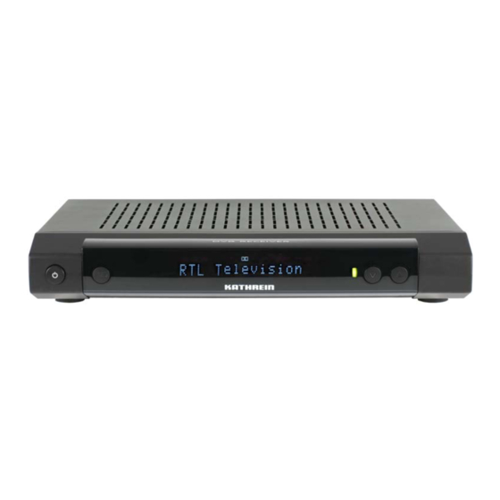
RECEIVER FEATURES/SCOPE OF SUPPLY The UFS 710si and UFS 710sw receivers are suitable for receiving digital satellite TV and radio channels. The built-in Common Interface offers space for two CA modules for pay-TV channels and ensures a guaranteed future. The receiver indicates the channel name on the 16-character alphanumeric display. The display also has 16 icons that provide information on specifi... -
Page 8: Controls, Displays And Connections
CONTROLS, DISPLAYS AND CONNECTIONS This section provides a brief description of all the controls, displays and connections. VIEW OF FRONT PANEL (FLAP FOLDED DOWN) VIEW OF REAR PANEL Front panel controls and displays On/Off switch (with mains disconnect) Display (cover folded down) Common Interface for two CA modules for Pay-TV cards * Ejection button for CA modules... -
Page 9: Connection And Set-Up
The following section is intended specifi cally for specialist dealers. You only need read this section if you are performing the installation yourself. The “Connection Examples” section provides a sample confi guration. Do not connect the unit to the mains until all installation work has been properly carried out. Refer to the information in the “Safety Instructions”... -
Page 10: Inserting Batteries Into The Remote Control
TV AND VIDEO RECORDER CONNECTION Connect the satellite receiver (TV Scart socket) and the TV set using a Scart cable (see “Connection Example”). If your TV has a stereo feature, you can receive the sound in stereo via the Scart connection. Use a further Scart cable to connect the satellite receiver (VCR/Scart socket) to the video recorder/PVR. -
Page 11: Remote Control
Sound on/off Switch on/input digits for channels, timer etc. Call up Main Menu, exit the menu and return to the TV picture (red) Call up favorites selection (green) “Current” view in the EPG Volume Exit menu step by step Changing channel in the programme guide (EPG) Transparent videotext Currently not used... -
Page 12: Remote Control Rc
For operating the fi rst receiver (address 1), press , for the second receiver , for the third receiver and for the fourth receiver (red) = Kathrein UFD 5xx code for remote control RC 400 The RC 600 and RC 650 remote controls are not interchangeable! -
Page 13: First Installation
FIRST INSTALLATION: General Before using your unit for the fi rst time, read the “Safety Instructions” and “Connection and Setup” sections. The “Connection examples” section provides a sample confi guration. Do not connect the unit to the power supply until all installation work has been properly carried out. - Page 14 FIRST INSTALLATION: General Use the buttons to select whether to replace the default channel list with one presorted for Germany, Austria, Switzerland or Italy. If you want to use the default channel list, choose “No” under “Restore Channellist”. Press the Use the buttons here to select the settings for your TV set.
- Page 15 FIRST INSTALLATION: General Picture format Here you select the type of screen display, depending on the setting of your TV format: TV format “4:3”: Pan & Scan or Letterbox TV format “16:9”: Always 16:9 or automatic TV-SCART-Output Select the type of video signal at the TV Scart socket here. Select the signal that your TV set can process. CVBS –...
- Page 16 FIRST INSTALLATION: DiSEqC™1.0 When selecting the satellite(s), make sure that your reception position is aligned to the desired satellite(s)! Number of Satellites Use the buttons to select how many satellites (max. 4) you would like to receive with your reception system.
- Page 17 FIRST INSTALLATION: DiSEqC™1.0 LNB Type Here use the buttons to select the LNB type used in your system. The choice is between “Universal” and “User-defi ned”. Universal: No further input is required, since all necessary frequency ranges are covered by a universal LNB. User-defi...
- Page 18 FIRST INSTALLATION: SIMPLE LNB Satellite and position Use the buttons to select the desired satellite whose signal is to be received by the tuner. When you have selected your desired satellite, use the buttons to switch to the selection of the “LNB Type”.
- Page 19 FIRST INSTALLATION: SIMPLE LNB User-defi ned: If you choose not to use a universal LNB, you must here set the frequency ranges for which your LNB was confi gured. Use the buttons to select the frequency range to be changed (low, high or limit frequency). Use the buttons or the digital input buttons to set the exact frequency for which your LNB was confi...
- Page 20 LNB type used in your system. The choice is between “Universal”, “Wideband” and “User-defi ned”. If in your reception system you use a single-cable LNB (e.g. UAS 481 from Kathrein), please select here the setting “Wideband”. If you use a single-cable matrix (EXU 908) or a single-cable switching matrix (EXR 501, 551, 552, 1581 or 2581) from Kathrein, the LNB you use must be a “Universal LNB”!
- Page 21 FIRST INSTALLATION: Single-cable system Universal: No further input is required, since all necessary frequency ranges are covered by a universal LNB. Wideband: No further input is necessary, since all frequency ranges are set by the Wideband LNB. User-defi ned: If you are not using a Universal or a Wideband system, you must set the frequencies here. You can fi nd the necessary information in the documentation supplied with your system.
- Page 22 FIRST INSTALLATION: Single-cable system (Automatic) If one or more receivers are already present on the system and an additional receiver is to be connected, when assigning the transmission frequency the new receiver make sure that no transmission frequencies are duplicated. No frequency can be used by more than one receiver.
- Page 23 fi tted (refer to the manuals, instructions and notes for the system and the system components). Available options: User-defi ned KATHREIN UAS 481 (single-cable feed system, max. four receivers) KATHREIN EXR 551 (single-cable switching matrix, max. four receivers) KATHREIN EXR 552 (single-cable switching matrix, max. two receivers) KATHREIN EXU 908 (single-cable matrix, max.
- Page 24 FIRST INSTALLATION: Single-cable system (Manual) Test connection When you have completed all the settings, press the buttons to switch to the “Test connection” selection fi eld and press the button. The receiver now tests whether a connection to the single-cable system can be established or not.
- Page 25 FIRST INSTALLATION: Single-cable system (Manual) Selection “UAS 481” or “EXR 551” When the “UAS 481” single-cable feed system is being used, it is essential that the LNB is set to “Wideband”! When the “EXR 551” single-cable switching matrix is being used, it is essential that the LNB is set to “Universal”! Transmission channel...
- Page 26 FIRST INSTALLATION: Single-cable system (Manual) Selection “EXR 552” When the “EXR 552” single-cable switching matrix is being used, it is essential that the LNB is set to “Universal”! Transmission channel Use the buttons to select a free available transmission channel. A maximum of two transmission channels are available (1400 and 1516 MHz).
- Page 27 FIRST INSTALLATION: Single-cable system (Manual) Selection “EXU 908” When the “EXU 908” single-cable matrix is being used, it is essential that the LNB is set to “Universal”! Transmission channel Use the buttons to select a free available transmission channel. A maximum of eight transmission channels are available (1284, 1400, 1516, 1632, 1748, 1864, 1980 and 2096 MHz).
- Page 28 FIRST INSTALLATION: Single-cable system (Manual) Selection “4 subscriber” When the “4 subscriber” single- cable switching matrix is being used, it is essential that the LNB is set to “Universal”! Transmission channel Use the buttons to select a free available transmission channel. A maximum of four transmission channels are available (1284, 1400, 1516 and 1632 MHz).
- Page 29 FIRST INSTALLATION: Single-cable system (Manual) Selection “8 subscriber” When the “8 subscriber” single- cable switching matrix is being used, it is essential that the LNB is set to “Universal”! Transmission channel Use the buttons to select a free available transmission channel. A maximum of eight transmission channels are available (1284, 1400, 1516, 1632, 1748, 1864, 1980 and 2096 MHz).
- Page 30 FIRST INSTALLATION: Channel search Execute Channel search Use the buttons to select (yes or no) whether you wish to start a channel search. It is not essential to start a channel seach; instead you can use the factory pre-programmed channels. However the channels do change from time to time (e.g.
- Page 31 FIRST INSTALLATION: Channel Search/Date and Time Use the button to move to the next step of the First Installation. The following display appears: Local time offset Use the buttons to set the time zone variation from UTC (formerly GMT) (e.g. for Germany +1 hour). Use the buttons to switch to the “Automatic clock change”...
-
Page 32: Operating Instructions
MENU CONCEPT The structure of the menu concept is based on logical operating sequences. The programme showing on the current selected channel always appears in the top right-hand corner of the screen. You will fi nd detailed descriptions of the selected menu items in the relevant sections of the operating manual! Note: The selected menus, sub-menus and positions, as well as the parameters to be set, are each... -
Page 33: Menu Tree
OPERATING INSTRUCTIONS MENU TREE Main Menu Call up the Main Menu by pressing the button... -
Page 34: Alphanumeric Inputs
ALPHANUMERIC INPUTS Use the displayed keypad (see fi gure to the right) for entry of favorites names or search expressions by selecting numerals for the desired letters/digits. You can choose between upper or lower case letters ( numeric pad to select the desired character. About two seconds after selection of the character, the cursor moves automatically to the next position. -
Page 35: On-Screen Displays (Osd)
ON-SCREEN DISPLAYS (OSD) CHANNEL MESSAGES TV CHANNEL MESSAGES $=Encrypted channel Channel number from the overall list Number of soundtracks (yellow) button Display of start time for current and next programmes Channel information is shown for a few seconds each time the channel is changed (this can be changed under “Settings”, “Adjust Displays”) or displayed continuously by pressing the RADIO CHANNEL MESSAGES The information for the current radio channel has the same layout. -
Page 36: Option Selection
ON-SCREEN DISPLAYS (OSD) the channels using the channel directly using the OPTION SELECTION Press the (yellow) button once (twice for portal channels) to view further soundtrack selection options, if these are transmitted by the channel provider. Use buttons to scroll through the available selection options. - Page 37 ON-SCREEN DISPLAYS (OSD) To the right of it you see the current channel list sort order as selected by you.The channel list can show channels sorted by various selection and sorting criteria. Selection and sorting options: Press the (red) button to call up the favorites list selection. The through the existing favorites lists.
-
Page 38: Epg - Electronic Programme Guide
EPG - ELECTRONIC PROGRAMME GUIDE CALLING UP THE EPG The EPG is called up by pressing the be shown the “Current” view, irrespective of which view you were shown the last time you exited the EPG. The following display appears (example): Channel number from the overall... -
Page 39: Current" View
EPG - ELECTRONIC PROGRAMME GUIDE Selection options: (red) button Calls up the plan recording (display of all pre-programmed recordings) button Jump the “Current” view forwards by 15 minutes (yellow) button Call up a preview of the currently highlighted channel (blue) button Call up the category selection (sorting the programmes by categories such as movies, sport, series ...) button... -
Page 40: Preview View (Programme Listings)
EPG - ELECTRONIC PROGRAMME GUIDE available you can use the button to call up further information on the desired programme. The allows you to look ahead in 15-minute steps to future programmes for the channels (press the to return to the current time). If you wish to view the programme currently being shown on a channel, you need not exit the EPG, just select the desired channel and press the current TV picture for the selected channel. -
Page 41: Categories View
EPG - ELECTRONIC PROGRAMME GUIDE CATEGORIES VIEW The “Categories” view can be called up at any time in EPG by pressing the (blue) button. In the “Categories” view you can see all programmes sorted by category and starting time. The following categories are available for selection: Movies, Series, Sport, Children’s programmes, Chat shows, News, Magazines/Reportage, Art/Culture, Science/Education, Music, Leisure and Adult programmes. -
Page 42: Search Function
EPG - ELECTRONIC PROGRAMME GUIDE SEARCH FUNCTION The search function can be called up at any time in EPG by pressing the button. The search function allows you to search for programmes based on their additional information or their name. Use the keypad to input the desired search expression (see also “Operating Instructions” “Alphanumeric Input”). -
Page 43: Additional Information (I Button)
EPG - ELECTRONIC PROGRAMME GUIDE ADDITIONAL INFORMATION (i BUTTON) The additional information can always be called up by pressing button whenever the “i symbol” appears in front of the program name (see screenshot on the right). First however the channel must be selected. The following display appears (example): The additional information available for a programme is displayed in its own window. -
Page 44: Recording (Timer)
EPG - ELECTRONIC PROGRAMME GUIDE RECORDING (TIMER) (red dot) button allows you to set up a programme at any time for recording on an external recorder. The programme to be recorded can be selected in any of the EPG views, provided the appears at the bottom of the screen display. -
Page 45: Record Once
EPG - ELECTRONIC PROGRAMME GUIDE RECORD ONCE Use the buttons to select the recording mode “once” (see screenshot item “Recording (Timer)”). Use the buttons to switch to the selection fi eld “Date” and use the recording date. Use the buttons to switch to the selection fi eld “Start” and use the pad to select the desired recording starting time. -
Page 46: Record Weekly
EPG - ELECTRONIC PROGRAMME GUIDE RECORD WEEKLY Remember that the day of the week for the desired programme is loaded in the recording schedule and you can make no further manual corrections to it! Therefore before pressing the day of the week that in future you will wish to make the weekly recording. Use the buttons to select the recording mode “weekly”... -
Page 47: Series Recording
EPG - ELECTRONIC PROGRAMME GUIDE Use the buttons to switch to the selection fi eld “End” and use the pad to select the desired recording ending time. When all settings have been made, press the recording in the Timer List view of the EPG (see item “Plan recording”). SERIES RECORDING Series recording depends on the EPG data being kept up to date at all times. -
Page 48: Plan Recording
EPG - ELECTRONIC PROGRAMME GUIDE PLAN RECORDING The “Timer List” view can be called up at any time in EPG by pressing the (red) button. The timer list view shows you all the recordings that are scheduled. buttons allow the recordings to be sorted into “once-only recording” or “Repeating” recordings. The cursor buttons ( ) allow you to select a recording. -
Page 49: Common Interface
IMPORTANT INFORMATION Always follow the operating instructions from your Pay-TV provider and the instructions supplied with the Smartcard and the CA module! Smartcards and CA modules are not included with this product! The cards and modules are issued by the respective Pay-TV providers, and contain the subscriber data and details of the channels for which the subscriber has paid. - Page 50 You can fi nd out which Conditional Access modules are in the CI slots on the UFS 710 and which Smartcard is in which CA module from the “Mainmenu” under “Settings”, and the “Common Interface” menu. Confi rmation is by pressing the Use the buttons to select one of the two slots in which the CA module is located (“Module inserted”) and then press the...
-
Page 51: Videotext (Teletext)
This symbol in the channel notifi cation shows you whether Videotext/Teletext is available for the selected channel. When you press the button, the receiver processes the broadcast Videotext/Teletext service for your TV set to display, even when the signal is encrypted. During the search, the page which is being searched for is displayed in the top left-hand corner with the time and date displayed at the top right. -
Page 52: Edit Channel List
Select the “Edit TV-Channellist” menu using the menu button Also attention bars at the bottom of the on- screen display! These provide information on what to do next. When the menu is called up, the standard setting is for the receiver to show the “All Satellites” channel list with all channels available on the satellites that are being received. -
Page 53: Editing Lists/Channels
EDITING LISTS/CHANNELS When you have selected the channel or channel list to be edited, press the the edit menu. You have the following edit options: Move: Channel can be moved within the current list to another channel slot Delete: Delete the channel from the current list Skip: Channel will be skipped when zapping through the channels Lock:... -
Page 54: Last Function" Memory
“LAST FUNCTION” MEMORY The last editing action performed is saved on the channels you will repeat the action without having to call up the edit menu again. As soon as you leave the current display, this option lapses and becomes available again only after the edit menu has been called up and an action selected. -
Page 55: Lock Channels
LOCK CHANNELS Use the buttons to select the channel to be locked in the current channel list. Press the to call up the edit menu and use the pressing the button. You are now prompted to enter the PIN code (factory default setting: 0000). The channel you previously selected is now shown with a padlock to its right. -
Page 56: Edit Favorites Lists
EDIT FAVORITES LISTS When you have selected the Favorites List to be edited (called up using the using the buttons), press the You have the following edit options: Remove from the Favorites List: The channel will be removed from the Favorites List Lock: Channel can be viewed only by inputting a PIN Rename Favorites List:... -
Page 57: Lock Channels
LOCK CHANNELS Use the buttons to select the channel to be locked from the Favorites List you have selected. Press the button to call up the edit menu and use the Confi rm the command by pressing the (factory default setting: 0000). The channel you previously selected is now shown with a padlock to its right. -
Page 58: Search Channels (Channel Search)
SEARCH CHANNELS (CHANNEL SEARCH) Select the “Search Channels” menu using the menu button Also pay attention to the bars at the bottom of the on-screen display! These provide information on what to do next. You have three options for a channel scan: Automatic Channel Search - all transponders for the satellite you selected will be scanned Manual Channel Search - only the selected transponder for the satellite you selected will be scanned Search with Service ID -... - Page 59 SEARCH CHANNELS (CHANNEL SEARCH) Satellite Select the satellite to be scanned, using the to the selected satellite. You can scan only one satellite at a time. If you have connected a multi-feed reception system (e.g. reception of ASTRA 19.2° East and HOTBIRD 13° East), you must repeat this procedure once for each satellite.
-
Page 60: Manual (Channel) Search
SEARCH CHANNELS (CHANNEL SEARCH) Newly found channels are identifi ed with the designation “new” after the channel name. After completion of the search, you will see the following message (example): Press the button. You will be asked whether you wish to save the changes or not. Selection is performed using the buttons and is confi... - Page 61 SEARCH CHANNELS (CHANNEL SEARCH) buttons allow you to select different sets of parameters for the scan. Satellite Use the buttons to select the satellite on which the transponder you wish to scan is located. Make sure your reception system is aligned to the selected satellite. You can scan only one transponder at a time.
-
Page 62: Channel Scan With Service Id
SEARCH CHANNELS (CHANNEL SEARCH) Press the button. You will be asked whether you wish to save the changes or not. Selection is performed using the buttons and is confi rmed using the button. If you select “Yes, save changes”, the newly found channels will be added to the end of the channel list. - Page 63 SEARCH CHANNELS (CHANNEL SEARCH) Press the button to move to the next selection item. Transponder Frequency Use the buttons or the numeric keypad to select the transponder frequency on which the channel being sought is transmitted. At the bottom right of the screen display, the receiver shows the current signal strength and signal quality of the selected transponder.
-
Page 64: Parental Control
Select the “Parental control” menu using the menu button . You are now prompted to enter the PIN code (factory default setting: 0000). After entering the PIN using the numeric keypad you are shown the following display: Also attention bars at the bottom of the on- screen display! These provide information on what to do next. -
Page 65: Define New Pin Code
DEFINE NEW PIN CODE Press the button to replace the old PIN with a new one. Enter the new (four-digit) PIN. For security you must repeat the new PIN code once again. Confi rm the change of PIN code by pressing the Keep your password in a safe place, so that you always have access to your channels even if you might have forgotten it. -
Page 66: Settings
The selected menus, sub-menus and positions, as well as the parameters to be set, are each highlighted in colour. The menus are to a large extent self-explanatory. Pay attention to the bar at the bottom of the on-screen display. These provide information on what to do next. -
Page 67: Tv Settings
TV SETTINGS TV ASPECT RATIO Here you can use the buttons to select the format for your TV. Either 4:3 or 16:9 format. PICTURE FORMAT Here press the buttons to select the screen display mode: • Pan & Scan • Letter-Box •... -
Page 68: Television System
VCR-SCART-OUTPUT Here you can use the the signal that your external recorder can process. When doing this, refer to the operating instructions for your recorder! • CVBS – Composite colour baseband signal (colour/picture/blanking/synchronization signal) • Y/C – S-Video signal (luminance/chrominance) TELEVISION SYSTEM Here, you can use the •... - Page 69 FUNCTIONAL RANGE Here you can confi gure the functional range of your receiver. You can choose between “Complete”, “Simple” and “Medium”. The following table shows which functions are available at each confi guration step. (red) button Complete Select favorites Simple Not assigned Medium Select favorites...
-
Page 70: Date And Time
SETTINGS DATE AND TIME Local time offset Use the buttons to set the time zone variation from UTC (formerly GMT) (e.g. for Germany +1 hour). Use the buttons to switch to the “Automatic clock change” fi eld. Automatic clock change Use the buttons to select whether the receiver should automatically change over to and from summer and winter time. -
Page 71: Service Menu
SERVICE MENU Select the “Service” menu using the menu button , the buttons on the main menu and The following display appears: Current software version Hardware version Channel list status Last update run UPDATE SOFTWARE The receiver checks in standby mode whether a new software version is available and, if it is, displays the following message the next time the receiver is started up: Use the buttons to select from the displayed options and press... - Page 72 Also attention bars at the bottom of the on- screen display! These provide information on what to do next. Update Software If new software is available (but only then), use the to load the new software that is available. If you are unsure whether you wish to load the new software, you can initially set the reply to “No”.
-
Page 73: Restore Factory Default Settings
SERVICE MENU When you have made your settings, use the buttons to select “Start Update” and press the button to start the update. The following display appears (see example on next page): RESTORE FACTORY DEFAULT SETTINGS Select the “Service” menu using the menu button , the buttons on the main menu and Use the... -
Page 74: Connecting Up The Video/Pvr
CONNECTING UP THE VIDEO/PVR For details of how to connect your external recorder to the receiver refer to the connection diagram provided at the end of this manual and the instructions for the external recorder. RECORDING In order to make a PVR recording (Record), the satellite receiver must be switched on or the timers must be pre-programmed (see “EPG”... -
Page 75: Using The Front Panel
If you have misplaced your remote control, or if the batteries are fl at, you can still operate your receiver from the front panel. BACKUP OPERATION There are three buttons on the front of the receiver. TV/R button: Pressing the TV/R button switches the receiver from TV mode to radio mode. Pressing the TV/R button a second time switches the receiver from radio mode back into TV mode. -
Page 76: Technical Appendix
16-character alphanumeric display with status icons for indication of channel names and transmitter information Common interface for two CA modules ¹ Kathrein Convenience EPG with timer programming ² Suitable for software download via satellite and PC 8 favourite channel lists for TV and 8 for... - Page 77 Sat-IF input/output (loop-through) TV/VCR output Video output Audio output (analogue) Audio digital output (electrical/optical) Data interface Common Interface General Permissible ambient temperature Unit dimensions/weight TECHNICAL APPENDIX UFS 710si 20210109/silver dBµV MSymb/s MBit/s mVss VAC/Hz V/mA 22; DiSEqC °C mm/kg UFS 710sw...
-
Page 78: Scart Socket Assignment
SCART SOCKET ASSIGNMENT Signal Right audio output Right audio input Left audio output Audio earth Blue earth Audio left input Blue signal Switching voltage Green earth Data signal Green signal Data signal Red earth Data earth Red signal (C) Blanking signal Video earth Blanking signal earth Video output (FBAS/Y) -
Page 79: Connection Example
CONNECTION EXAMPLE Digitalton AC 3 Digital audio AC 3 optisch/elektrisch optical/electrical Cinch Hi-fi system TECHNICAL APPENDIX Dolby Digital system Cinch Scart Scart PVR (VCR) Scart Scart Infra-red receiver Infrarot-Empfänger (optional) (optional) -
Page 80: Examples Single-Cable Systems
EXAMPLES single-cable systems EXR 501/551/552 Single-cable switching matrices The receiver must be programmed for single-cable commands Overvoltage protection KAZ 11/KAZ 12 TECHNICAL APPENDIX 4 x single – or 2 x twin receivers Sat IF... - Page 81 TECHNICAL APPENDIX The receiver must be programmed for single-cable commands Overvoltage protection KAZ 11/KAZ 12 UAS 481 Single-cable feed system...
- Page 82 EXR 1581/2581 Single-cable matrices Sat IF The receiver must be programmed for single-cable commands Overvoltage protection KAZ 11/KAZ 12 TECHNICAL APPENDIX...
- Page 83 EXU 908 Single-cable matrix The receiver must be programmed for single-cable commands Overvoltage protection KAZ 11/KAZ 12 TECHNICAL APPENDIX Quatro LNB UAS 484/584 Sat IF...
-
Page 84: Short Technical Guide
SHORT TECHNICAL GUIDE CHANNEL PACKAGE The channel package for a digital transponder normally includes several TV and radio channels. Each channel package has a fi xed assignment for the transponder transmission frequency, for polarisation (horizontal or vertical), for the symbol rate and for the Viterbi rate or error rate. DISEQC™... -
Page 85: Symbol Rate
SHORT TECHNICAL GUIDE The PID (Packet IDentifi cation) number is an identifi cation number for video signals and audio signals in the digital data stream of DVB-MPEG-2 signals. The receiver uses the PID number to create a unique assignment for the video and audio data transmission. The PCR PID is the identifi cation number for the synchronization signal. -
Page 86: Glossary
Clock function for pre-programmed switch on and off times Timeshift function Time-shifted playback Transponder See “Short technical guide” UFO ® micro and Kathrein-specifi c satellite signal processing systems UFO ® mini VCR connection Video recorder connection Viterbi rate See “Short technical guide”... -
Page 87: Troubleshooting
In the event of a malfunction, fi rst check all the cable connections and operating states: 1. Receiver and TV set power plugs are connected to the wall socket 2. Antenna cables are located on the receiver input 3. Receiver and TV set correctly interconnected by a Scart or cinch cable 4. - Page 88 Internet: http://www.kathrein.de KATHREIN-Werke KG • Anton-Kathrein-Straße 1 - 3 P.O. Box 100 444 • 83004 Rosenheim GERMANY...
Need help?
Do you have a question about the UFS 710si and is the answer not in the manual?
Questions and answers