Table of Contents
Advertisement
Quick Links
Advertisement
Table of Contents

Subscribe to Our Youtube Channel
Related Manuals for Kathrein MSK 24


Summary of Contents for Kathrein MSK 24
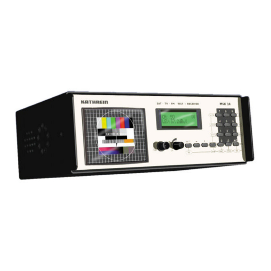
- Page 1 Operating Manual Satellite / TV / Radio Test Receiver MSK 24 Order No. 208 323...
-
Page 3: Preface
As of August 2000 Dear Customer, Kathrein-Werke KG has made every effort to ensure that this manual is correct and complete. No liability can be assumed for any mistakes that may still be contained in the manual or for any damage resulting from such mistakes. -
Page 4: Table Of Contents
General Notes... 6 Explanation of symbols ... 6 Safety instructions ... 6 How it operates... 7 Overview of functions... 8 Block diagram of MSK 24... 9 Technical Data ...10 Operating and display elements ...12 Display elements ...12 LC display ...12 TFT colour screen ...12... - Page 5 Customer service...45 Technical Appendix...46 Signal-to-noise distance...46 DiSEqC commands for Kathrein matrices ...47 Command set for Kathrein matrix 9xx-series ...47 Command set for Kathrein matrix EXR 20...47 Command set for Kathrein matrix EXR 22...47 Channel tables ...48 Channel and frequency table for B/G standard (frequency in MHz)...48 Channel and frequency table for L standard (frequency in MHz)...49...
-
Page 6: General Notes
• Do not apply a low-frequency AC voltage to the HF socket The receiver is also live when disconnected. Use only the power supply unit supplied to power the MSK 24. A voltage of between 10 V and 20 V is available at the RF input socket depending on the programming. -
Page 7: How It Operates
How it operates How it operates The MSK 24 is designed as a universal portable test receiver for TV, SAT and FM radio for both battery and mains operation. A built-in lead battery with 2.8 Ah and a plug-in power unit for 230 V AC are included with the receiver. -
Page 8: Overview Of Functions
Overview of functions Overview of functions Function Mains and battery operation Level measurement by entering frequency Level measurement by entering channel Level-dependent acoustic signal Loudspeaker for acoustic check Reception of multiple standards (B/G, D/K, I, L, Nicam, M/N, M1) Nicam audio reception and L standard Audio carrier setting Audio carrier measurement Adjustable LNB voltage supply... -
Page 9: Block Diagram Of Msk 24
Block diagram of MSK 24 Block diagram of MSK 24... -
Page 10: Technical Data
Technical Data Technical Data Power supply Mains operation Battery operation Capacity Dimensions Weight Safety standards Display Temperature range Frequency range Channel allocation Frequency tuning Measuring errors RF input RF input separator Level measurement range Measuring bandwidth Measuring detector Return loss FM threshold Audio IF bandwidth Audio deemphasis... - Page 11 Technical Data Audio processing SAT FM audio processing FM + Nicam in quasi parallel audio mode AM in parallel mode (only L standard) B/G standard D/K standard I standard M/N standard M1 standard L standard B/G standard I standard FM audio processing Audio carrier measurement Nicam decoder Audio carrier distance...
-
Page 12: Operating And Display Elements
The colour screen has a diagonal of 4“ and a resolution of 238 x 480 pixels. The light intensity is 250 cd/m². MSK 24 Sat-Ctrl Level Ch-Frq Sat/TV 2ndF... -
Page 13: Overview Of The Keyboard Commands
Ch-Freq No function DVB/analogue switch-over Scan Search for a satellite irrelevant of frequency Level Spect Setup Keyboard of MSK 24: Sat-Ctrl See above for details Level Ch-Frq Sat/TV 2ndF Brief description of the function for Switch-over to SAT reception... -
Page 14: Connections
Otherwise the battery of the MSK 24 will be discharged! The visual and audio signals are available at the Scart socket on the right side of the MSK 24 for assessment on an external monitor. -
Page 15: Starting Up
Turn the on/off switch towards the right. Set the desired volume. The LC display shows the software version and serial number of the MSK 24 for approx. 1 second. Then the LC display indicates the capacity of the battery for approx. 3 seconds. -
Page 16: Setup Menu
In the next menu you are requested to set the mute function by pressing button [1] or [2]. Select "ON" to mute the MSK 24 as long as the input signal on the RF input is below 30 dBìV. -
Page 17: Mains And Battery Operation
Mains and battery operation Mains operation Battery operation The MSK 24 can be powered from the mains or the built-in battery. Use only the batttery charger/power supply unit supplied for mains operation. Connect the power supply unit to the voltage supply socket on the right side of the receiver. -
Page 18: Sat Measurement
1=ANALOG 2=DIGITAL(DVB) Standard menu FR:1288.0MHz LEV: 66.5dBuV Display for DVB measurement In the SAT mode the MSK 24 can be set to receive the following types of signal: analogue and digital (DVB). [2ndF] [STD] Call up standard switch-over menu: [1]...[2]... -
Page 19: Frequency Display And Entering Frequency
Mode: SAT Level: 86.5 dBìV A + or – in the display means that MSK 24 has not been tuned in exactly to the desired carrier. Use the [+] and [-] buttons to adjust the frequency for the best possible reception. When a vertical line appears in the display, the frequency has the best possible setting. -
Page 20: Level Measurement
Sat measurement Level Measurement FR:1508.0MHz LEV: 86.5dBuV Level Overflow and Underflow FR:1508.0MHz LEV: __._dBuV FR:1508.0MHz LEV: dBuV Note only Once you have set a frequency, the level is measured automatically and displayed in dBìV or dBmV (depending on the basic configuration) on the LC display. -
Page 21: Tracking Satellites
Sat measurement Tracking Satellites Overview of commands in SCAN ë LEV-Range:2 > Example The "SCAN" function can search for satellites whose exact transponder frequencies are unknown. The frequency range from 1000 to 2100 MHz is scanned continuously to detect signals. If signals are received, the reception level is indicated in a bar display. -
Page 22: Tracking For Single Frequencies
Sat measurement Tracking for Single Frequencies Overview of commands in Tracking ë LEV-Range:2 > Example In the "LEVEL " function you can align an antenna by tracking to receive the maximum signal. The level tendency can be indicated in the bar display. -
Page 23: Audio Carrier Frequency
Audio carrier bandwidth: narrow = 150 kHz Mode: SAT After the SAT mode has been called up, the MSK 24 is always set to the audio carrier 7.02 MHz. Changes made to the frequency of the audio carrier are only retained until you exit the SAT mode. -
Page 24: Lnb Voltage And 22 Khz / 60 Hz Switch-Over
Sat measurement LNB Voltage and 22 kHz / 60 Hz Switch-Over Overview of commands in LNB Voltage ë Example LNB:14,0V 150mA Note The LNB supply voltage is available at the RF socket. This is confirmed by the LED next to the RF socket which lights up when the voltage supply is switched on. - Page 25 Sat measurement Example LNB:14,0V 22kHz 150mA Note Switch on the 22 kHz signal. Press button [8]. LC display: LNB voltage 14 V Current consumption 150 mA The 22 kHz signal is switched on. By pressing button [8], you can switch off the 22 kHz signal. By calling up another function, e.g.
-
Page 26: Diseqc (Digital Satellite Equipment Control)
Framing Address parity bit The MSK 24 can also transmit signals to DiSEqC 1.0 but it cannot receive them. [2ndF] [SAT-CTRL] Call up the DiSEqC menu [0]...[9] Enter the code words in hexadecimal code 0...9 [.] [0]...[5]... -
Page 27: Overview Of Commands In Framing Byte
Note Overview of commands in Framing Byte ë You want to test the Kathrein matrix EXR 22. The command set for the matrix EXR 22 is E0 00 24 (LNB High) and E0 00 20 (LNB Low). Call up DiSEqC: Press buttons [2ndF] [SAT-CTRL] Press button [3] to call up the DiSEqC control. -
Page 28: Overview Of Commands In Address Byte
Sat measurement Overview of commands in Address Byte ë Hex byte Description All equipment Every LNB, matrix or SMATV LNB with loop-through Matrix (switcher) Matrix (switcher) with loop-through SMATV Every polarizer Maximum rotation (full skew) with lineal polarization Set polarizer in steps Every positioner Polar / Azimuth positioner Elevation positioner... -
Page 29: Overview Of Commands In Command Byte
Overview of commands in Command Byte ë The MSK 24 can send commands in accordance with DiSEqC 1.0 but it cannot receive them. All commands that require DiSEqC 2.0 (to send and receive) are shown in grey in the table. - Page 30 Sat measurement B inactive) Set S3A Call up matrix S3 input A (input B inactive) Set S4A Call up matrix S4 input A (input B inactive) Set S1B Call up matrix S1 input B (input A inactive) Set S2B Call up matrix S2 input B (input A inactive) Set S3B Call up matrix S3 input B (input...
-
Page 31: Overview Of Commands In Data Byte
Sat measurement Overview of commands in Data Byte ë Simple Tone Burst DiSEqC Overview of commands in Simple DiSEqC ë An appropriate data byte only needs to be sent when the command byte requires data byte(s). You can see this in the above command byte table. You can find out which data byte has to be sent to which command byte in the data sheets for the relevant receiver. - Page 32 Sat measurement Example SAT-CTRL LNB=1 V-SEC=2 DiSEqC=3 SAT-CTRL menu DiSEqC-Framing DiSEqC menu DiSEqC-SIMPLE 0 Tone BURST > Simple DiSEqC menu Call up Simple DiSEqC: Press buttons [2ndF] [SAT-CTRL] Press button [3] to call up DiSEqC control. The cursor must be positioned on the left with the [-] button. Press button [0] or [1] to call up the Simple DiSEqC menu.
-
Page 33: V-Sec (Vario-Satellite Equipment Control)
Sat measurement V-SEC (Vario-Satellite Equipment Control) Overview of commands in V-SEC ë Example SAT-CTRL LNB=1 V-SEC=2 DiSEqC=3 SAT-CTRL menu SAT-CTRL LNB=1 V-SEC=2 DiSEqC=3 V-SEC menu Overview of commands in V-SEC V-SEC provides unidirectional communication between satellite receivers and peripheral components in a satellite receiving system and serves to control intelligent multiswitches with several inputs, coaxial relays or rotation systems. -
Page 34: Tv Measurement
2=DIGITAL(DVB) 1. Standard menu 1=BG 3=DK 5=MN 6=M1 2. Standard menu Note In the TV mode the MSK 24 can measure the following standards: B/G standard L standard D/K standard I standard M/N standard M1 standard (Japan) [2ndF] [STD] Call up standard switch-over menu [0]...[6]... -
Page 35: Channel Display And Entering Channel
TV measurement Channel Display and Entering Channel Overview of commands in Entering Channel (TV) ë Example CH:S.11. LEV: 62.5dBuV Note To measure the level of a received TV signal, you must first enter the desired channel. The following channels can be set: Band I / III CH 01 to CH 12 in the 7 MHz raster Band IV / V CH 21 to CH 70 in the 8 MHz raster Special channel... -
Page 36: Frequency Display And Entering Frequency
Once you have called up the frequency menu, you only need to enter the figures to enter the frequency again. The last frequency setting is retained even when the MSK 24 is switched off provided it was made using "numerical entries" and concluded with... -
Page 37: Level Measurement (Tv)
TV measurement Level Measurement (TV) CH: .05. LEV: 86.5dBuV Level Overflow and Underflow CH: .05. LEV:___._dBuV CH: .05. LEV: . dBuV Note Once you have set a channel or a frequency, the level is measured automatically and indicated in dBìV or dBmV (depending on the configuration of the receiver) on the LC display. -
Page 38: Tracking For Single Frequencies
TV measurement Tracking for Single Frequencies Overview of commands in Tracking ë LEV-RANGE:2 > Example In the "LEVEL " function you can align an antenna by tracking to receive the maximum signal. The level tendency can be indicated in the bar display. -
Page 39: Audio Carrier Distance And Level
TV measurement Audio Carrier Distance and Level Overview of commands in Measuring Audio Carrier Frequency ë Example SC: 5.50MHz LEV: -13.0dB SC: 5.50MHz LEV: 58.5dBuV TV transmitters can use a second audio carrier to transmit information using FM modulation (analogue) or in Nicam format (digital). Different frequencies are allocated to the audio carriers depending on the standard being used (see table). -
Page 40: Measuring The Audio Carrier Distance And Level Of Nicam Audio Carriers
TV measurement Measuring the Audio Carrier Distance and Level of Nicam Audio Carriers: Note NICAM – Measuring Audio Bit Error Rates Example Calling up Measuring Audio Bit Error Rates: SC: 5.85 MHz BER=2.145E-05 As above. Press button [2] during the audio carrier display. As above. -
Page 41: Fm Measurement
Once you have called up the FM menu, you only need to enter the figures to enter the frequency again. The last frequency setting is retained even when the MSK 24 is switched off provided it was made using "numerical entries" and concluded with "MHz". -
Page 42: Tracking For Single Frequencies
FM measurement FR:104,80MHz LEV:¯¯¯.¯dBuV Tracking for Single Frequencies Overview of commands in Tracking ë LEV-RANGE:2 > Example The LC display shows an overflow level of >120 dBìV. Frequency: 104.8 MHz Mode: TV Level: overflow In the "LEVEL " function you can align an antenna by tracking to receive the maximum signal. -
Page 43: Spectrum Measurement
Spectrum measurement Spectrum measurement Sat Spectrum SAT-Full TV Spectrum To assess a receiving system you can display the frequency spectrum for Sat, TV and FM on the screen. You can call up Spectrum Measurement from the relevant mode (Sat, TV or FM). -
Page 44: Fm Spectrum
Spectrum measurement Overview of commands in TV Spectrum ë TV full TV narrow FM Spectrum FM CCIR LC displays and ranges: FULL SPAN = entire TV range (44…867 MHz) VHF (44…467 MHz) UHF (467…867 MHz) NARROW (e.g. 634…659 MHz) You can select and measure the FM spectrum as described above. It covers 87…108 MHz. -
Page 45: Maintenance
Beware that the polarity of the battery is correct. Battery: YUASA NP2.8-12 12V / 2.8Ah Send the receiver to the following address for any service work: ESC - GmbH Bahnhofstr.108 83224 Grassau Tel.: +49 (0)8641 / 9545-0 Fax: +49 (0)8641 / 9545-35 Internet: www.esc-kathrein.de... -
Page 46: Technical Appendix
(set parabola antenna so that no satellite signal is received) max. receiving level bandwidth correction. This gives the following formula: Measured bandwidth of MSK 24 6 MHz RF bandwidth of receiving signal Receiving signal level Background noise level Carrier-to-noise distance C/N... -
Page 47: Diseqc Commands For Kathrein Matrices
POS. B (Satellite 2) Range Low band Vert. DiSEqC E0 00 38 F4 command Command set for Kathrein matrix EXR 20 EXR 20 Range POS. A DiSEqC E0 00 22 command Command set for Kathrein matrix EXR 22 EXR 22... -
Page 48: Channel Tables
266.25 273.25 280.25 287.25 294.25 Channel raster: 7 MHz for VHF and USB/OSB - 8 MHz for UHF and ESB The channel, display on the MSK 24 and frequency are shown in the table. UHF-CCIR 471.25 479.25 487.25 495.25 503.25 511.25... -
Page 49: Channel And Frequency Table For L Standard (Frequency In Mhz)
223.25 Video and audio assessment and level measurement of the audio carrier are not possible for the channels marked with *. The channel, display on the MSK 24 and frequency are shown in the table. 21 471.25 22 479.25 23 487.25 24 495.25... -
Page 50: Channel And Frequency Table For D/K Standard (Frequency In Mhz)
R-XI 11 215.25 R-XII 12 223.25 50.00 60.00 70.00 75.00 80.00 90.00 175.00 200.00 The channel, display on the MSK 24 and frequency are shown in the table. 471.25 479.25 487.25 495.25 503.25 511.25 519.25 527.25 535.25 543.25 551.25 559.25 567.25... -
Page 51: Channel And Frequency Table For I Standard (Frequency In Mhz)
207.25 215.25 223.25 231.25 239.25 247.45 50.00 60.00 70.00 75.00 80.00 90.00 175.00 The channel, display on the MSK 24 and frequency are shown in the table. 471.25 479.25 487.25 495.25 503.25 511.25 519.25 527.25 535.25 543.25 551.25 559.25 567.25 575.25... -
Page 52: Channel And Frequency Table For M1 Japan Standard (Frequency In Mhz)
S13 S13 295.25 S14 S14 301.25 S15 S15 307.25 S16 S16 313.25 S17 S17 319.25 S18 S18 325.25 S19 S19 331.25 The channel, display on the MSK 24 and frequency are shown in the table. 471.25 477.25 483.25 489.25 495.25 501.25 507.25... -
Page 53: Channel And Frequency Table For M/N Standard (Frequency In Mhz)
181.25 A09 09 187.25 A10 10 193.25 A11 11 199.25 A12 12 205.25 A13 13 211.25 The channel, display on the MSK 24 and frequency are shown in the table. 471.25 477.25 483.25 489.25 495.25 501.25 507.25 513.25 519.25 525.25 531.25... -
Page 54: Channel And Frequency Table For M/N Standard (Frequency In Mhz)
KK 47 S39 361.25 LL 48 367.25 MM 49 S41 373.25 NN 50 S42 379.25 The channel, display on the MSK 24 and frequency are shown in the table. Special channels OO 51 385.25 PP 52 391.25 QQ 53 397.25 RR 54 403.25... -
Page 55: Notes
Notes Notes... - Page 56 KATHREIN-Werke KG ž Telephone +49 (0) 80 31 18 40 ž Fax +49 (0) 80 31 18 43 06 Anton-Kathrein-Strasse 1-3 ž Postfach 10 04 44 ž D-83004 Rosenheim...
Need help?
Do you have a question about the MSK 24 and is the answer not in the manual?
Questions and answers