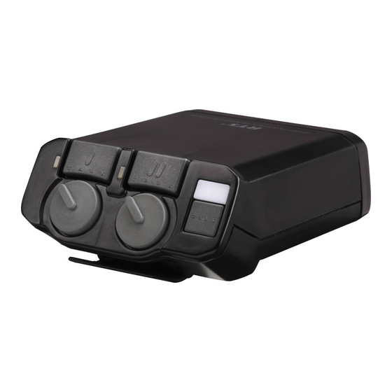
RTS BP325 User Manual
Belt-pack intercom station
Hide thumbs
Also See for BP325:
- Specifications (2 pages) ,
- User manual (28 pages) ,
- User manual (16 pages)
Table of Contents
Advertisement
Quick Links
Advertisement
Table of Contents

Related Manuals for RTS BP325


Summary of Contents for RTS BP325
- Page 1 USER MANUAL MODEL BP325 Belt-Pack Intercom Station ™ 9350-5690-00 Rev H 8/02...
- Page 3 4. Limited Liability: The liability of the Company for any claims arising out of this License based upon the Software, regardless of the form of action, shall not exceed the greater of the license fee for the Software or $50. 38109-709 Rev A 10/97 BP325 User Manual...
- Page 4 This warranty is the sole and exclusive express warranty Upon completion of any repair the equipment will be given with respect to RTS products. It is the responsibility returned via United Parcel Service or specified shipper of the user to determine before purchase that this product collect.
-
Page 5: Table Of Contents
GENERAL ............5 METHOD 1: ONE CHANNEL OPERATION WITH A NON-RTS POWER SUPPLY ....5 METHOD 2: TWO CHANNEL OPERATION WITH A NON-RTS POWER SUPPLY . - Page 6 Figure 1. BP325 Reference View BP325 User Manual...
-
Page 7: Connections And Operation
CONNECTIONS AND OPERATION This section describes operation of the BP325 as supplied from the factory. Use of an RTS power supply to power the intercom system is assumed. For options and use of an alternate power source, see “Programmable Options”, page 3 and “Alternate Powering Methods, page 6. -
Page 8: Programmable Options
Set W1 to “off” to disable channel 1 intercom audio listen to the left headphone. Set DIP switch 4 to “on” to disable channel 1 talk. (See option note 6.) Setup the left channel for program input. (See option note 2.) BP325 User Manual... - Page 9 To use program audio input: Unplug the LINE LOOP connector from J6, and plug it into J5. (Refer to the label inside the BP325 rear cover.) If you are using a stereo headset: set W3 and/or W4 to “on” to route the program audio to the left headphone, right headphone or both headphones.
-
Page 10: Sidetone Adjustment
TALK button(s). Release the mic switch to turn off the TALK button(s). Note: the TALK buttons may still be turned on or off from the BP325; however, the external mic switch will not work unless the TALK buttons are first turned on at the BP325. -
Page 11: Alternate Powering Methods
GENERAL When using an RTS power supply to power the intercom system, power is carried to the BP325 on pin 2 of the LINE INPUT connector along with the channel 1 audio. Pin 1 is the DC return. The unique design of RTS power supplies permits power to be carried on an audio channel. - Page 12 Pin 2, Ch 1 +Audio TO BP325 LINE INPUT 200 Ohms 200 Ohms TO INTERCOM CHANNELS 10mF / 50V 10mF / 50V Pin 1, Common Figure 5. LINE INPUT Connector Wiring for 2-Channel Operation with Non-RTS Power Supply BP325 User Manual...
-
Page 13: Specifications
0 dBm = 1 milliwatt Monaural Dynamic-mic Headset Connector XLR-4-31 receptacle (J13) Pin 1 - Microphone low All product information and specifications subject to Pin 2 - Microphone high change without notice. Pin 3 - Common Pin 4 - Headphone high BP325 User Manual... - Page 14 REPLACEMENT PARTS ELECTRICAL PARTS WHERE TO OBTAIN PARTS ELECTRICAL PARTS Ref No. Description RTS Part No. Parts may be obtained directly from RTS at: Telex/RTS Systems C102 Capacitor, Elect, 22uF, 50V 1513-R226-4I 12000 Portland Avenue South C103 Capacitor, Elect, 22uF, 50V...
- Page 15 D312 Diode, Signal, 1N914B 1601-0914-0B R115 Resistor, Carbon, 100K, 5%, 1/4W 1402-1003-5D D314 Diode, Rectifier, 7A, MR752 1601-0752-00 R116 Resistor, Carbon, 2.2M, 5%, 1/4W 1402-2204-5D D315 Diode, Signal, 1N914B 1601-0914-0B R117 Resistor, Carbon, 1.0M, 5%, 1/4W 1402-1004-5D BP325 User Manual...
- Page 16 Resistor, Carbon, 470 ohm, 5%, 1/4W 1402-4700-5D U401 Voltage Regulator, LM317HVK 1603-0009-00 R323 Resistor, Metal Film, 42.2K, 1%, 1/4W 1403-4222-2D U402 IC, Dual Op-amp, NE5532N 1603-5532-0N R325 Resistor, Metal Film, 100 ohm, 1%, 1403-1000-2D U601 IC, Dual Op-amp, NE5532N 1603-5532-0N 1/4W BP325 User Manual...
- Page 17 Date: 8/12/02 Time : 02:41:05 PM Title: c:\home\cms\benedil\view\AS6634_01.CAL...
- Page 18 Date: 8/12/02 Time : 02:50:15 PM Title: c:\home\cms\benedil\view\AS6635_01.CAL...
- Page 19 Date: 8/12/02 Time : 02:52:12 PM Title: c:\home\cms\benedil\view\AS6736_01.CAL...
- Page 20 Date: 8/12/02 Time : 02:53:16 PM Title: c:\home\cms\benedil\view\AS6737_01.CAL...
- Page 21 Date: 8/12/02 Time : 02:54:14 PM Title: c:\home\cms\benedil\view\AS6738_01.CAL...
- Page 22 Date: 8/12/02 Time : 02:55:23 PM Title: c:\home\cms\benedil\view\SD6634_01.CAL...
- Page 23 Date: 8/12/02 Time : 02:37:17 PM Title: c:\home\cms\benedil\view\SD6635_01.CAL...
- Page 24 Date: 8/12/02 Time : 02:39:57 PM Title: c:\home\cms\benedil\view\SD6635_02.CAL...
Need help?
Do you have a question about the BP325 and is the answer not in the manual?
Questions and answers