Table of Contents
Advertisement
Quick Links
Advertisement
Table of Contents

Related Manuals for RTS BP-6000


Summary of Contents for RTS BP-6000
- Page 1 Universal Beltpack Technical Manual BP-6000 Rev. 03 May/2018 F.01U.350.550...
- Page 2 Universal Beltpack – BP-6000 Proprietary Notice The product information and design disclosed herein were originated by and are the property of Bosch Security Systems, Inc. Bosch reserves all patent, proprietary design, manufacturing, reproduction, use and sales rights thereto, and to any article disclosed therein, except to the extent rights are expressly granted to others.
- Page 3 Universal Beltpack – BP-6000 Important Safety Instructions Read these instructions. Keep these instructions. Heed all warnings. Follow all instructions. Do not use this apparatus near water. Clean only with dry cloth. Do not block any ventilation openings. Install in accordance with the manufacturer’s instructions.
- Page 4 Universal Beltpack – BP-6000...
-
Page 5: Table Of Contents
System Configuration .........................13 Power ..............................13 Channel Power ...............................13 Local Power ..............................15 INITIAL SETUP AND CONFIGURATION ................17 Initial BP-6000 Setup ..........................17 Setup Mode Indication ........................18 Firmware Version ..........................18 Programming the Beltpack ........................19 Enter Program Menu ..........................19 Exit Program Menu ..........................19 Menu System ............................ - Page 6 Universal Beltpack – BP-6000 OPERATION AND MAINTENANCE ..................27 Operation ...............................27 Adjust the Volume ..........................27 Change the Channel ........................... 27 Maintenance ............................28 Replace the Beltclip ........................... 28 Set Local Power ..........................29 Notes ..............................31...
-
Page 7: Introduction
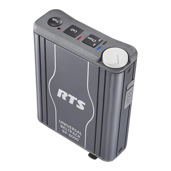
CHAPTER 1 Introduction The BP-6000 is a portable user station compatible with Audiocom and Clear-Com party line systems. It is only available as a 2-channel version. The BP-6000 is a 2-channel beltpack equipped with a mode- sensing system configuration, meaning it determines what type of system it is installed into and configures itself according to the system. -
Page 8: Reference View
8 Introduction Universal Beltpack – BP-6000 Reference View Reference View FIGURE 1. -
Page 9: External Connections And Controls
Mode Menu” on page 21 Headset Connector: The connector accepts an RTS headset with a boom microphone. Line Connector: The BP-6000 intercom channel is connected via a 6-pin female connector and is powered through the intercom system power supply. -
Page 10: Connector Description
10 Introduction Universal Beltpack – BP-6000 Connector Description XLR (6-Pin Switchcraft) The BP-6000 Beltpack uses a IMPORTANT: Switchcraft 6-pin layout. This layout differs from the legacy Neutrik 6-pin layout used in previous models. The adapter cables are a available for purchase (see Figure 2). -
Page 11: Specifications
Universal Beltpack – BP-6000 Introduction 11 Specifications Frequency Response 200Hz – 8kHz Power Requirements Noise Contribution Max. Operating Current (unbalanced) <-60 dBu 50 mA Total Harmonic Distortion Max. Operating Current (balanced) <1.0% 55 mA Terminating Impedance Channel Supplied Balanced 18–33 VDC ... - Page 12 12 Introduction Universal Beltpack – BP-6000 Call Signaling Send DC only Receive DC only Total Harmonic Distortion <1.0% Headphone Amplifier Maximum Output >140 mW into 150 load Frequency Response 200 Hz -8 kHz ±3dB Audible Alert 1 kHz Total Harmonic Distortion <1.0%...
-
Page 13: System Configuration And Power
Balanced Audio – Uses differential mode signalling. Power The BP-6000 use an external power supply unit, such as a PS-20, PS-2001L, PS-4001, etc to power the beltpacks. Power is passed through the beltpacks via the Intercom Channel Connector (See Figure 1 on page 8). - Page 14 14 Introduction Universal Beltpack – BP-6000 Single Power Supply System FIGURE 3. Two Power Supply System FIGURE 4.
-
Page 15: Local Power
Universal Beltpack – BP-6000 Introduction 15 Two Local Power Settings in a System FIGURE 5. Local Power The Local Power setting is used to isolate the DC power (voltage) so line noise is reduced without losing signal voltage. Use the local power setting when you have two power supplies feeding a system of beltpacks over a long distance (up to 1000 feet supported). - Page 16 16 Introduction Universal Beltpack – BP-6000...
-
Page 17: Initial Setup And Configuration
LEDs upon power up or through the program menu. The factory setting for the BP-6000 is Audiocom mode. For more information on the different modes of operation, see “System Configuration” on page 13. -
Page 18: Setup Mode Indication
18 Initial Setup and Configuration Universal Beltpack – BP-6000 Setup Mode Indication When power is applied to beltpack, the LED lights blink to indicate the setup mode it is currently running. Audiocom – LEDs blink six times in three seconds Clear-Com –... -
Page 19: Programming The Beltpack
Universal Beltpack – BP-6000 Initial Setup and Configuration 19 Programming the Beltpack Enter Program Menu To enter the program menu, do the following: Put the headset on your head. Press and hold the TALK and CALL buttons simultaneously for three seconds. -
Page 20: Menu System
20 Initial Setup and Configuration Universal Beltpack – BP-6000 Menu System... -
Page 21: Talk Mode Menu
Universal Beltpack – BP-6000 Initial Setup and Configuration 21 Talk Mode Menu The Talk Mode menu is used to program how the TALK button operates. Available menu options are: Switched (d) – The TALK button toggles on and off as long as the button press is less the 400msec. If the TALK button is held longer, the button does not latch on. -
Page 22: Mic Gain Menu
22 Initial Setup and Configuration Universal Beltpack – BP-6000 Mic Gain Menu The Mic Gain menu is used to set the mic gain for the beltpack. Mic gain adjusts the audio level being sent out on the line. Available options for this menu are 1, 2, 3, 4, and 5. -
Page 23: Incoming Call Beep Menu
Channel Lock Menu The Channel Lock menu is used to program whether the BP-6000 has access to one or two channels. When channel lock is used, the beltpack only operates on the locked channel. For example, if channel 1 is locked, the beltpack only operates on channel 1. -
Page 24: Power Source Menu (Audiocom Only)
24 Initial Setup and Configuration Universal Beltpack – BP-6000 Power Source Menu (Audiocom Only) The Power Source menu is used to select which channel the beltpack draws power. By distributing the power draw, more beltpacks can be used on the same party-line. -
Page 25: Send Mic Kill Menu (Audiocom Mode Only)
Universal Beltpack – BP-6000 Initial Setup and Configuration 25 Send Mic Kill Menu (Audiocom Mode Only) The Send Mic Kill menu is used to send a shut off signal to a microphone on a beltpack, user station, or master station that has been left on. A 24 kHz signal is sent to the party-line where the beltpack with the microphone left on, signalling it to shut off. -
Page 26: Factory Reset
26 Initial Setup and Configuration Universal Beltpack – BP-6000 Factory Reset The Factory Reset menu is used to reset the beltpack to its original, factory settings. Available options are Yes or No. The default for this menu is Off. To perform a factory reset on the beltpack, do the following: While in the program menu, navigate to Factory Reset. -
Page 27: Operation And Maintenance
CHAPTER 3 Operation and Maintenance Operation Adjust the Volume To adjust the volume on the beltpack, do the following: On the top panel of the beltpack, turn the volume knob clockwise to increase the volume. > Turn the volume knob counterclockwise to decrease the volume. Change the Channel To change the channel on the beltpack, do the following: On the top panel of the beltpack, press the CH 1/2 button once. -
Page 28: Maintenance
28 Operation and Maintenance Universal Beltpack – BP-6000 Maintenance Replace the Beltclip To replace the beltclip on the beltpack, do the following: Using a screwdriver, remove the two locking washers and screws holding the beltclip in place. Set the washers and screws aside for later use. -
Page 29: Set Local Power
Universal Beltpack – BP-6000 Operation and Maintenance 29 Set Local Power Local Power is set by shorting pins on the J3, J4 and J5 jumper located on the PCBA board. The board must be removed from the beltpack housing to make this adjustment. For more information on Local power, see “Local Power”... - Page 30 30 Operation and Maintenance Universal Beltpack – BP-6000 Being careful not to pull the connectors from the headers, attach jumpers to J3, J4 and J5 on the board, as described in Table 3. If you need to move the connector wires to access the J4 jumper, gently push them to IMPORTANT: either side.
-
Page 31: Notes
Universal Beltpack – BP-6000 Operation and Maintenance 31 Notes... - Page 32 Bosch Security Systems, Inc. 12000 Portland Avenue South Burnsville, MN 55337 U.S.A. www.rtsintercoms.com...
Need help?
Do you have a question about the BP-6000 and is the answer not in the manual?
Questions and answers