
Related Manuals for RTS BP300


Summary of Contents for RTS BP300
-
Page 1: User Manual
User Manual MODEL BP-300 Portable Belt Pack User Station 9350-1786-00 Rev H 09/2006... -
Page 2: Copyrightnotice
OTICE The product information and design disclosed herein were originated by and are the property of Telex Communications, Inc. Telex reserves all patent, proprietary design, manufacturing, reproduction, use and sales rights thereto, and to any article disclosed therein, except to the extent rights are expressly granted to others. -
Page 3: Table Of Contents
TABLE OF CONTENTS ........... . PROPRIETARYNOTICE . - Page 4 MICROPHONE Page...
-
Page 5: Section 1: Description And Specifications
The user talks and listens using the headset (or a handset). The headset con- nects to the BP300 via a four conductor cable and connector (optionally five or six pin). The BP300 connects to the system using a three conductor "microphone"... - Page 6 1.3 BP300 SPECIFICATIONS Input DC Voltage Mode 18 to 35 volts DC 15 to 35 volts DC LP Option Battery 12 to 35 volts DC (reduced performance) DC Current Drawn from TW Line (Note: LP Option draws no current from TW line)
-
Page 7: Section2.Installation
Below that voltage, a safety circuit disables the microphone switch on the CC33 board. Twe of System The BP300 can be installed in a (1) three wire system, (2) two wire system, or (3) special two wire system. Method... -
Page 8: Choosing Headsets
Practically, the impedance has a larger effect with present day headsets. Impedance Low impedance headphones are louder, causing the BP300 to draw more current from the power supply. High impedance headphones are not as loud, drawing less current from the power supply. -
Page 9: Cablingrequlrements
PS31 power supply the maximum operating distance is 322,181160 milliamperes 5370 feet (1652 meters). The maximum operating distance using a PS8 power supply and a BP300 with 25 ohm phones (37 185,874137 5024 feet (1531 meters). > . ' 2.4.2... -
Page 10: Mechanical
Model 214 Crosstalk Cancellation Device. 2 5 Mechanical The BP300 user station is either clipped to a user's clothing for portable operation, or mounted on a structure, camera or vehicle. For permanent installation, temporarily remove the electronics from the case. Drill, deburr and fasten the case as necessary, then reinstall the electronics. - Page 11 25 dB to 35 dB Television Studio Voice, Whisper Typical Operating Environments, Sound Pressure Level, Source Maximum Allowable Impulse Exposure 140 dB LH267 BP300, 10 db below Clipping DT109 BP300, 120 dB 10 db below Clipping 110 dB LH268 BP300, 10 db below Clipping...
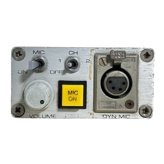
- Page 12 Figure 3-1A Front Panel, Model BP300 Portable Belt Pack User Station CAR6 MIC H D S T ~ Figure 3-1U Rcar Pancl, Modcl BP300 Portablc Bclt Pack Uscr Station Page...
-
Page 13: Section3.Operation
SECTION OPERATION Operating Controls And Connectors Table 3-1 below lists the Model BP300 user station controls and connectors. The reference numbers in Table 3-1 correspond to the circled numbers in Figure 3-1A and Figure 3-1B. Ref No. Name CHannel Select Switch 1 2 Selects 1 of 2 channels (standard) or 1 of... - Page 14 Figure 3-2 I%lock Iliagram, Model RI'300 Page 14...
-
Page 15: Section 4: Replacement Parts
SECTION 4: REPLACEMENT PARTS 4.1 WHERE TO OBTAIN PARTS Parts may be obtained directly from Telex at: TelexIRTS Systems 12000 Portland Ave. S. Burnsville, 55337 877-863-4169 Fax: 800-323-0498 4.2 MECHANICAL PARTS FINAL ASSEMBLY (Refer to Drawing #AS1786 for ltem No. locations) item NO. - Page 16 CC-33 CIRCUIT BOARD ASSEMBLY Ref. No. Description Capacitor, CM, Rad, 0.01 pF, 200v C28,C29 Capacitor, EL, 10 pF, 50V Diode, Signal 1 N6263 D1-D3 Diode, 1 N5231 B D5,D6 Diode, 1 N4004, I A , 400V Diode, 1 N5245B Zener, Voltage Reg l 5 V Diode, 1 N5365B Zener, Voltage Reg 36V...
- Page 17 CC-40145 CIRCUIT BOARD ASSEMBLY Description Ref. Resistor, CF, 100 Ohm, 1/2W, 5% Resistor, CF, loOK, 114W, 5% Resistor, CF, loOK, 114W, 5% Resistor, CF, 22K, 114W, 5% Resistor, CF, 150 Ohm, 114W, 5% Resistor, CF, 2.7 Ohm, 1/4W, 5% Resistor, CF, 22K, 114W, 5% Resistor, CF, 36 Ohm, 1/2W, 5% R4 1 Resistor, CF, 1.3K, 114W, 5%...
- Page 18 This page intentionally left blank. Page...
-
Page 19: Section 5: Diagrams 1 Drawings
Schematic Diagram, Phase 3 User Stations, sheet 1 of 2 . SD1427~00 Schematic Diagram, Phase 3 User Stations, sheet 2 of 2 Call Light Option used by both Model BP300 User Stations with CC33 card (Standard units and units with Call Light Option). SD1470... - Page 20 WEIGHT: 1 .OLBS (.45kg) ALL DIMENSIONS: INCHES(mrn) OD3415 Outline Drawing, BP300 Page 20...
- Page 21 > 2 " > > To Supply Cable Wiring Diagram Two Channel System Channel 2 Common Channel 1 Common Drain Wires - - - - c - To Station Page > > >...
- Page 22 > Bl k N.C. N.C. 4 . 1 Common To Supply Cable Wiring Diagram Three Channel System Channel 3 Drain Wires Common . Page 22 > N.C. To Station...
- Page 23 12V Battery Operation...
- Page 26 P.C.B. CC - 4 0 DYNAMIC MIC CONNECTOR X L R - 4 STANDARD MOMENTARY SD1427-01 (Simplified) Schematic Diagram, Phase 1 1 1 User Stations (CC-40) DYNAMIC M I C CONNECTOR Hp HPHI LAST USED' C43,CR8,J4,83,R44,55, V R 3 NOT USED: CI,C18,CZI,C22)C33-C41,CRI,Q2, R 2 , R 1 3 , R 2 7 , R 3 0 - R 3 5 , R37,...
- Page 27 Assembly Diagram, P.C.B. CC40/45 Layout...
- Page 29 E OPTION CC-45 ONLY -RHC (*M) O P T I O N O P T I O N (*B) XLR-5-32 A 5 F CONNECTION CC-45 ONLY MS6 O P T I O N (FOR SD1427-00 Schematic Diagram, Pl~ase User Stations, Sheet 2 of 2 Page...
- Page 32 BLUE 9" DETAIL A DETAIL B I T EM 17fI8 ARE TW/STED W I E S . PART NUMBERS O€SCR/P7'ION S E l SEPARATE PARTS 9 0 2 0 - /787-OCd REVlSlONS RIV. DCIOlWmOU REV/JED PER /266 > REQD SEE DETAIL O A n A??noWO 7.5084...
- Page 33 MISTED PAlR MISTED PAlR GRN 9' MISTED PAlR (PIN (PIN 1) (PIN 3) DETAIL A SEE DETAIL A SEE DETAIL B...
Need help?
Do you have a question about the BP300 and is the answer not in the manual?
Questions and answers