Table of Contents
Advertisement
Quick Links
Download this manual
See also:
User Manual
Advertisement
Table of Contents

Related Manuals for Atag A200SOV


Summary of Contents for Atag A200SOV
- Page 1 I n s t a l l a t i o n & S e r v i c i n g Instructions A200SOV Open vent heat only boiler Boiler G.C No A200SOV 41-310-15 CE PIN 0063BT3195 These instructions to be retained by user.
- Page 2 Explanation of the control panel display and keys Flame Indication that the boiler is on Bell Error indication Spanner Service-mode or blocking Radiator Indication that the boiler is on LCD display with backlight Heating program ba r °C ( OK ) Directly operated soft cushion keys ( ESC) Scroll and +/-function...
-
Page 3: Table Of Contents
Content Introduction ............................4 Rules ............................4 Delivery package ..........................6 Boiler description ..........................6 Mounting the boiler .........................7 Dimensions .........................8 Connecting the boiler ........................9 Open vent heating system ....................9 Heating systems with plastic pipes ...................10 Gas connection ......................... 11 Condensation drain pipe ....................11 Flue gas exhaust system and air supply system ..............13 6.5.1 Dimensioning of the flue gas and air intake duct ............17 Electrical connection ........................18... -
Page 4: Introduction
Bord Gais installers in connection with the installation and putting into operation of ATAG boilers. It is advisable to read these instructions thoroughly, well in advance of installation. Separate instructions for use are supplied with the boiler for users of ATAG central heating boilers. - Page 5 British Standards. The ATAG A boiler is a certified appliance and must not be modified or installed in any way contrary to this Installation Manual. Manufacturers instructions must not be taken in any way as overriding statutory obligations.
-
Page 6: Delivery Package
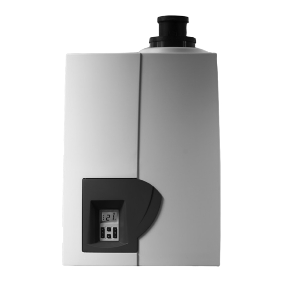
Circulation pump • Programmer, room thermostat and cylinder thermostat. Boiler description The ATAG A is a room sealed, condensing and modulating CH boiler. Room sealed boiler The boiler retrieves its The boiler is equipped with a compact stainless steel heat exchanger with smooth pipes. -
Page 7: Mounting The Boiler
Mounting the boiler The room where the boiler will be placed must always be frost free. The boiler casing is splash water tight (IPX4D) and is suitable to be installed in e.g. a bathroom. It is NOT necessary to have a purpose provided air vent in the room or internal space in which the boiler is installed. -
Page 8: Dimensions
5.1 Dimensions Top view Left side view Front view ceiling minimum 250mm Bottom view keteltype A200SOV Flue gas / Air intake 60/100 ½" Gas connection int. CH Flow connection CH Return connection Condensate drain connection connection diameters tabel 2 dimensions (in mm) Figure 2... -
Page 9: Connecting The Boiler
Connecting the boiler The boiler has the following connection pipes; The central heating pipes. These can be connected to the installation by means of compression fittings / adapter fittings; The gas pipe. It is provided with a female thread into which the tail piece of the gas isolation valve can be screwed;... -
Page 10: Heating Systems With Plastic Pipes
Additives in the installation water are only permitted in consultation with the country distributor. ATAG Heating UK Ltd recommend the use of either Fernox or Sentinel products. 6.2 Heating systems with plastic pipes... -
Page 11: Gas Connection
Make sure that the gas pipe work does not contain dirt, particularly with new pipes. When the boiler has to be converted from natural gas to LPG, ATAG provides special kits for this purpose. Special instructions are supplied with the kit. - Page 12 Terminate as close to the ground or drain as possible (below the grating and above the water level) while still allowing for safe dispersal of the condensate. Connection of a condensate drainage pipe to a drain may be subject to local building controls.
-
Page 13: Flue Gas Exhaust System And Air Supply System
6.5 Flue gas exhaust system and air supply system The flue gas exhaust system and air supply system consists of: Flue gas pipe; Air supply pipe; Roof or wall terminal. The flue gas exhaust system and air supply system must comply with: United Kingdom: The flue gas outlet and air supply installation must comply with the current regulation requirements. - Page 14 The appliance concentric connection diameter is 60/100 mm, to which the flue gas outlet and air supply system can be fitted, with or without elbow pieces. The maximum permissible pipe length is set out in Table 5. Boiler conversion from concentric to parallel It is also possible to use a parallel pipe connection of 2x 80mm.
- Page 15 Monopass Flue system literature. The ATAG flue gas system is meant and designed solely for the use on ATAG central heating boilers adjusted to Nat gas or LPG. The maximum flue gas temperatures are below 70°C (full load 80/60°C)
- Page 16 In certain weather conditions condensation may also accumulate on the outside of the air inlet pipe. Such conditions must be considered and where necessary insulation of the inlet pipe may be required. In cold and/or humid weather water vapour may condense on leaving the flue terminal. The effect of such ‘plumeing’...
-
Page 17: Dimensioning Of The Flue Gas And Air Intake Duct
A longer flue gas length can be achieved by increasing the diameter to ø 100mm. Example: An A200SOV with Explanation table 1: a concentric flue gas system Two pipe flue gas system: maximum noted length = distance between boiler and ø80/125mm has according... -
Page 18: Electrical Connection
Lead the cables from the controls along the the hing bracket and through the cable feed through in the back part of the boiler. For more detailed questions about components that have not been supplied by ATAG, contact the vendor concerned. -
Page 19: Electrical Diagram
7.2 Electrical diagram Figure 10... -
Page 20: Filling The System
Filling the system 8.1 CH Installation The CH installation should be filled with potable water. For filling the CH installation, use the the feed and expansion header tank. Filling is done as follows: 1 Ensure all system and boiler drain points are closed; 2 Open all isolation and motorised valves;... -
Page 21: Boiler Controls
If the supply temperature is below the T-set value of 20°C the boiler will immediately start. The ATAG A is equipped with boiler sensors of 10kOhm. The resistance value and corresponding temperature are shown in the accompanying table. -
Page 22: Explanation Of The Control Keys
9.1 Explanation of the control keys Hot water Not applicable Central heating Setting the CH water temperature: Briefly press + or - ; the display will show the flashing preset value; Briefly press + or – to change the set value. Each change becomes active directly. CH program OFF: Press –... -
Page 23: Commissioning The Boiler
Commissioning the boiler Before putting the boiler into operation make sure that the system has been filled and fully bled of any air and that the gas supply is turned on and has been purged. The boiler requires no adjustment of the burner pressure and quantity, because it is self-regulative and has been set in the factory and should not be reset. -
Page 24: Settings
There may be cases that the settings have to be changed, for example: Lower supply temperature Use the parameter chapter to set the boiler according to the situation. If in doubt, check with ATAG Heating Ltd. To change a setting, proceed as follows: Changing the settings Press the OK key for 3 seconds. -
Page 25: Activating The Factory Setting (Green Key Function)
Parameter-chapter PARA Factory Description Range Gradient speed CH 0 - 15 Do not change 0 - 10 K Do not change 10 - 40 max. Maximum power CH in % 0 - max Can only be reduced. 0 = low load Do not change 651* 1 - 3... -
Page 26: Isolating The Boiler
Switching on with the + key takes place in reverse order. ATAG recommends to leave the plug in the wall socket, so that the circulation pump is activated automatically once every 24 hours in order to prevent jamming. -
Page 27: Checking The O
12.1 Checking the O The O percentage is set in the factory. This has to be checked during inspection, maintenance and in case of a failure. This can be verified by means of the following action: Set the external controls to call for heat; Make sure the boiler is operational and can get rid of the heat it produces;... -
Page 28: Maintenance Activities
12.2 Maintenance activities In order to perform maintenance, the following actions have to be taken: switch off the boiler; remove the screws from the 4 quick fasteners A, B, C and D (see fig. 13); unlock the 4 quick fasteners A, B, C and D and remove the cover in a forward motion. Air box/cover The cover also doubles as air box: Clean the air box/cover with a cloth and a non-abrasive cleaner;... - Page 29 Ignition electrode Replacing the ignition electrode is necessary when the pins are worn. If the inspection hole is damaged, the entire ignition electrode has to be replaced. It is replaced as follows: disconnect the plug connections on the ignition electrode; push the clips on either side of the electrode outwards and pull out the electrode assembly;...
-
Page 30: Maintenance Frequency
12.3 Maintenance frequency ATAG advises an inspection of the boiler every year with a full service to be carried out at least every 4 years, depending on the operational hours listed in the warranty conditions. 12.4 Warranty For the warranty refer to the Warranty Card that is supplied with the boiler. -
Page 31: Technical Specifications
Technical specifications ATAG A-Series Solo Boiler type A200S OV Input Hs CH Input Hi CH Efficiency class according BED Efficiency according EN677 109,2 (36/30°C part load, Hi) Efficiency according EN677 97,9 (80/60°C full load, Hi) Modulation range CH 4,4 - 17,6 (capacity 80/60°C) -
Page 32: Parts Of The Boiler
Parts of the boiler boiler parts ATAG A figure 20 Heat exchanger Flue gas exhaust Ignition unit Combustion air supply Fan unit Data plate Air supply damper Gas valve Automatic air vent Control Management System Control panel Gas pipe Flow sensor Return sensor Flow pipe CH... -
Page 33: Declaration Of Conformity
Declaration of conformity CE DECLARATION OF CONFORMITY Hereby declares ATAG Verwarming Nederland BV that, the condensing boiler types: ATAG A200SOV are in conformity with the provisions of the following EC Directives, including all amendments, and with national legislation implementing these directives:... -
Page 34: Kiwa Certificate
Kiwa certificate... -
Page 35: Benchmark Checklist
Failure to install and commission according to the manufacturer’s instructions and complete this Benchmark Commissioning Checklist will invalidate the warranty. This does not affect the customer’s statutory rights. If yes, and if required by the manufacturer, has a water scale reducer been fitted? Condensing Boilers only The condensate drain has been installed in accordance with the manufacturer’s instructions and/or BS5546/BS6798 If the condensate pipe terminates externally has the pipe diameter been increased and weatherproof insulation fitted? -
Page 36: Service Record
service record It is recommended that your heating system is serviced regularly and that the appropriate Service Interval Record is completed. service Provider Before completing the appropriate Service Record below, please ensure you have carried out the service as described in the manufacturer’s instructions. - Page 40 ATA G H e a t i n g U K L t d . • U n i t 3 • B e a v e r Tr a d e P a r k • Q u a r r y L a n e C h i c h e s t e r W e s t S u s s e x P O 1 9 8 N Y Phone: 01243 815 770 • Fax 01243 839 596 • E-mail: info@atagheating.co.uk • Internet: www.atagheating.co.uk E.
Need help?
Do you have a question about the A200SOV and is the answer not in the manual?
Questions and answers