Nonin 7500 Operator's Manual
Pulse oximeter
Hide thumbs
Also See for 7500:
- Operator's manual (44 pages) ,
- Quick manual (2 pages) ,
- Quick start up manual (2 pages)
Table of Contents
Advertisement
Advertisement
Table of Contents

Subscribe to Our Youtube Channel
Related Manuals for Nonin 7500


Summary of Contents for Nonin 7500
- Page 1 Operator’s Manual Model 7500 Pulse Oximeter English 0123 0123...
- Page 2 MPS, Medical Product Service GmbH Borngasse 20 D-35619 Braunfels, Germany References to “Nonin” in this manual shall imply Nonin Medical, Inc. Nonin, PureLight, and nVISION are registered trademarks or trademarks of Nonin Medical, Inc. © 2016 Nonin Medical, Inc. 7928-001-04...
-
Page 3: Table Of Contents
Pulse Rate Display ....................6 Numeric LEDs ......................6 Indicators and Icons ....................7 Model 7500 Front Panel Buttons ................8 Operating the Model 7500 ................9 Operating Modes and Defaults..............10 Setup Mode, Viewing Limits and Setting Time ............. 10 Factory Defaults .................... - Page 4 Contents (Continued) Clearing Patient Memory ...................23 Playing Back Memory Data ................23 Connecting the Device into a Medical System ............24 Service, Support, and Warranty..............25 Warranty........................25 Parts and Accessories.................26 Troubleshooting ...................27 Technical Information ..................29 Manufacturer’s Declaration ...................29 Equipment Response Time...................32 Testing Summary ....................33 Accuracy Testing ..................33 Pulse Rate Motion Testing.................33 Low Perfusion Testing ..................33...
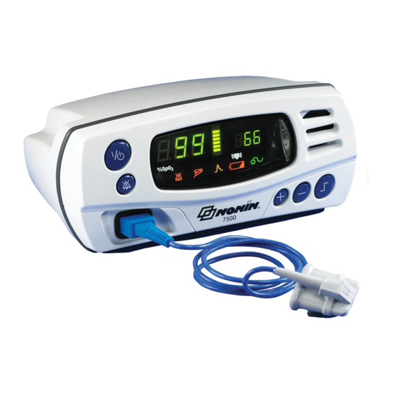
- Page 5 Figures Figure 1. Model 7500 Front View ................6...
- Page 6 Tables Table 1. Symbols ....................... 4 Table 2. Factory Default Settings................10 Table 3. Basic Functions..................13 Table 4. Limits Display Sequence................13 Table 5. Advanced Options..................14 Table 6. Patient Alarms.................... 18 Table 7. Equipment Alarms..................18 Table 8. Real-time Data Output ................21 Table 9.
-
Page 7: Indications For Use
Verify all alarm settings and limits during system startup to ensure that they are set as intended. A hazard can exist if different presets are used on multiple 7500 monitors in one care area. Do not use this device in or around water or any other liquid, with or without AC power. -
Page 8: Cautions
In some circumstances, however, the device may still interpret motion as good pulse quality. This device is a precision instrument and must be repaired by Nonin Technical Service. Field repair of the device is not possible. Do not attempt to open the case or repair the electronics. Opening the case may damage the device and void the warranty. - Page 9 Indications for Use Cautions (Continued) This device is designed to determine the percentage of arterial oxygen saturation of functional hemoglobin. Factors that may degrade pulse oximeter performance or affect the accuracy of the measurement include the following: - excessive ambient light - anemia or low hemoglobin concentrations - excessive motion - cardiogreen and other intravascular dyes...
-
Page 10: Guide To Symbols
Guide to Symbols Guide to Symbols This table describes the symbols that are found on the Model 7500. Detailed information about functional symbols can be found in “Operating the Model 7500.” Table 1: Symbols Symbol Description Caution! Consult instructions for use. - Page 11 Guide to Symbols Table 1: Symbols (Continued) Symbol Description Federal law (USA) restricts this device to sale by or on the order of a licensed practitioner. Lot Number Protected against spraying water and against access to hazardous parts with a IP33 tool, per IEC 60529.
-
Page 12: Displays, Indicators And Controls
Pulse Rate Display The pulse rate display is located on the right-hand side of the Model 7500 front panel and is identified by the symbol. This display shows the pulse rate in beats per minute, from 18 to 321. The numeric displays blink during pulse rate alarm conditions. -
Page 13: Indicators And Icons
Low Battery LED This amber LED indicates a low battery charge when blinking, and a critical battery charge when lit solidly. This LED does not indicate that the Model 7500 is running on battery power. WARNING: This device turns off after approximately 30 minutes when in low battery... -
Page 14: Model 7500 Front Panel Buttons
Model 7500 Front Panel Buttons ON/STANDBY Button Pressing this button once turns on the Model 7500. Holding this button for at least 1 second shuts down the 7500, putting it into Standby mode. In Standby mode, all device functions are shut off, with the following exceptions: •... -
Page 15: Operating The Model 7500
Verify that all LEDs illuminate and the unit beeps three times during the first phase of the initialization sequence. If any LED is not lit (except the AC Power Supply LED), do not use the Model 7500. Contact Nonin Technical Service for assistance. -
Page 16: Operating Modes And Defaults
In Factory Defaults, all adjustable parameters are set as indicated in the table below. This is the Model 7500’s default operating setting. The Model 7500 is shipped with factory defaults active. To revert to Factory Default alarm limits from the User-Defined Default alarm limits, simultaneously press the alarm silence and minus (-) buttons. -
Page 17: User-Defined Defaults
When the Model 7500 is turned on in Patient Security mode, “SEC on” is displayed in the display area, and three informational tones sound. The upper alarm limits are then displayed, followed by the lower alarm limits. -
Page 18: Viewing And Changing Patient Security Mode
Operating Modes and Defaults Viewing and Changing Patient Security Mode Enter Patient Security Mode – With the device off, press and hold the Alarm Silence button while turning the device on. Exit Patient Security Mode – With the device off, press and hold the Alarm Silence and Limits buttons while turning the device on. -
Page 19: Operator Functions
Operator Functions Operator Functions The Model 7500 has several easy-to-use basic functions. Most involve pressing only a single button. Table 3: Basic Functions Function Button Instruction Press the ON/STANDBY button to turn on the Model 7500. Press and hold the button for at least one Turn the Model 7500 second to turn off the Model 7500. -
Page 20: Table 5. Advanced Options
Select the Model 7500 option in nVISION software. NOTE: Alarm limits cannot be changed when the Model 7500 is in Patient Security mode. Patient Security mode prevents accidental changes to critical parameters. The Model 7500 allows users to lock and unlock alarm limits, volume settings, and time settings... -
Page 21: Function Button
Operator Functions Table 5: Advanced Options (Continued) Function Button Instruction Enter Patient To enter Patient Security mode, press and hold the Security Mode Alarm Silence button while turning on the device. Exit Patient Security To exit Patient Security mode, press and hold the Alarm Mode Silence and Limits buttons while turning on the device. -
Page 22: Care And Maintenance
5 years. Field repair of the Model 7500 circuitry is not possible. Do not attempt to open the Model 7500 case or repair the electronics. Opening the case may damage the Model 7500 and void the warranty. If the Model 7500 is not functioning properly, see “Troubleshooting.”... -
Page 23: Alarms And Limits
Alarms and Limits Alarms and Limits The Model 7500 is equipped with audio and visual alarm indicators to alert the operator to provide immediate patient attention or to abnormal device conditions. The intended operator’s position for correctly perceiving a visual alarm signal and its priority is 1 meter (3.3 feet), per IEC 60601-1-8. -
Page 24: Alarm Summary
Alarms and Limits Alarm Summary The Model 7500 detects both patient and equipment alarms. In general, patient alarms are identified as high priority, while equipment alarms are identified as medium priority. High priority alarms always take priority over medium priority alarms. Alarm indicators remain active for as long as the alarm condition is present. -
Page 25: Reviewing And Setting Volume And Alarm Limits
Reviewing and Setting Volume and Alarm Limits Reviewing and Setting Volume and Alarm Limits NOTE: Alarm limits reset themselves to default values each time the unit is powered up–unless the unit is in Patient Security mode. In Patient Security mode, alarm limits and volumes cannot be adjusted;... -
Page 26: Recalling Previous Settings
2. If the error persists, disconnect all power, and then reconnect the power and turn the unit back on. If the error still persists, note the error code and contact Nonin Technical Service at (800) 356-8874 (USA and Canada), +1 (763) 553-9968, or +31 (0)13 - 79 99 040 (Europe). -
Page 27: Memory And Data Output Features
Nonin, may be used to connect the Model 7500 to the receiving computer. The information from the Model 7500 is sent in an ASCII serial format at 9600 baud with 8 data bits, 1 start bit, and 2 stop bits. Each line is terminated by CR/LF. -
Page 28: Analog Output
Memory and Data Output Features Analog Output The Model 7500 provides analog output signals for SpO , pulse rate, and event markers. Each output level conforms to the specifications shown below: Output Specification Output Analog Range 0 - 1.0 VDC (representing 0-100%) 1.27 VDC (out of track) -
Page 29: Memory Features
Playing back the data does not clear the data from memory. 1. With the unit off, connect the serial connector port of the Model 7500 to the back of your computer using the 7500SC cable, which is available from Nonin. -
Page 30: Connecting The Device Into A Medical System
Memory and Data Output Features Connecting the Device into a Medical System Incorporating the device into a medical system requires the integrator to identify, analyze, and evaluate the risks to patient, operators, and third parties. Subsequent changes to the medical system after device integration could introduce new risks and will require additional analysis. -
Page 31: Service, Support, And Warranty
Accordingly, any sign or evidence of opening the Model 7500, field service by non-authorized personnel, tampering, or any kind of misuse or abuse of the Model 7500, shall void the warranty in its entirety. All non-warranty work shall be done according to Nonin standard rates and charges in effect at the time of delivery to Nonin. -
Page 32: Parts And Accessories
For more information about Nonin parts and accessories: • See the Parts and Accessories List on the Operator’s Manual CD. • Contact your distributor or Nonin at (800) 356-8874 (USA and Canada), +1 (763) 553 9968, or +31 (0)13 - 79 99 040 (Europe). -
Page 33: Troubleshooting
Plug in the AC power supply. activate. Model 7500 will not The battery pack is not charged. Plug in the Model 7500 AC power supply operate on batteries. to charge the battery pack. The battery pack is inoperable. Contact Nonin Technical Service for repair or replacement. - Page 34 Contact your distributor or Nonin Technical Service for repair or replacement. If these solutions do not correct the problem, please contact Nonin Technical Service at (800) 356-8874 (USA and Canada), +1 (763) 553-9968, or +31 (0)13 - 79 99 040 (Europe).
-
Page 35: Technical Information
Technical Information Technical Information NOTE: This product complies with ISO 10993, Biological Evaluation of Medical Devices Part 1: Evaluation and Testing. CAUTION: A functional tester cannot be used to assess the accuracy of a pulse oximeter monitor or sensor. CAUTION: All parts and accessories connected to the serial port of this device must be certified according to at least IEC Standard EN 60950, IEC 62368-1, or UL 1950 for data-processing equipment. -
Page 36: Table 10. Electromagnetic Immunity
Technical Information Table 10: Electromagnetic Immunity Electromagnetic Immunity Test IEC 60601 Test Level Compliance Level Environment—Guidance This device is intended for use in the electromagnetic environment specified below. The user of this device should ensure that it is used in such an environment. Electrostatic ±8 kV contact ±8 kV contact... -
Page 37: Table 11. Guidance And Manufacturer's Declaration-Electromagnetic Immunity
Technical Information Table 11: Guidance and Manufacturer’s Declaration—Electromagnetic Immunity IEC 60601 Test Compliance Immunity Test Electromagnetic Environment—Guidance Level Level This device is intended for use in the electromagnetic environment specified below. The user of this device should ensure that it is used in such an environment. Portable and mobile RF communications equipment should be used no closer to any part of the device, including cables, than the recommended separation distance calculated from the equation applicable to the frequency of the transmitter. -
Page 38: Equipment Response Time
Technical Information Table 12: Recommended Separation Distances This table details the recommended separation distances between portable and mobile RF communications equipment and this device. This device is intended for use in an electromagnetic environment in which radiated RF disturbances are controlled. -
Page 39: Testing Summary
Specific to this example: • The response of the 4-beat average is 1.5 seconds. Testing Summary accuracy, motion, and low perfusion testing were conducted by Nonin Medical, Inc., as described below: Accuracy Testing During motion and no-motion conditions at an independent research laboratory, SpO... -
Page 40: Principles Of Operation
Alarm Silenced: LED, amber Numeric Displays: 3-digit, 7-segment LEDs, green Low Battery: LED, amber Accuracy - Sensors: Declared accuracy for compatible sensors can be found in Nonin’s Sensor Accuracy document. Alarm Volume: High: 75 dBA Low: 63 dBA Informational Tone Volume:... - Page 41 Technical Information Power Requirements (Mains): 100-240 VAC 50-60 Hz Internal Power: Battery: 7.2 volt NiMH battery pack Operating Life (fully charged battery): 16 hours minimum Storage Life: 21 days minimum Recharge Rate: 4 hours maximum Dimensions: Approximately 219 mm (8.6”) W x 92 mm (3.6”) H x 142 mm (5.6”) D Weight: Approximately 900 grams (2 lbs) with battery...
Need help?
Do you have a question about the 7500 and is the answer not in the manual?
Questions and answers