Nonin 7500FO Operator's Manual
Hide thumbs
Also See for 7500FO:
- Quick manual (2 pages) ,
- Operator's manual (49 pages) ,
- Instructions for use (2 pages)
Table of Contents
Advertisement
Quick Links
Advertisement
Table of Contents

Subscribe to Our Youtube Channel
Related Manuals for Nonin 7500FO


Summary of Contents for Nonin 7500FO
- Page 1 Operator’s Manual Model 7500FO Pulse Oximeter English...
- Page 2 MPS, Medical Product Service GmbH Borngasse 20 D-35619 Braunfels, Germany References to “Nonin” in this manual shall imply Nonin Medical, Inc. Nonin, PureLight and nVISION are registered trademarks or trademarks of Nonin Medical, Inc. ® ® Microsoft and Windows are registered trademarks of Microsoft Corporation.
-
Page 3: Table Of Contents
Display....................... 6 Pulse Rate Display ....................6 Numeric LEDs ......................6 Indicators and Icons ....................7 Model 7500FO Front Panel Buttons ............... 8 Operating the Model 7500FO ..............10 Operating Instructions ................11 Operating in the MR Environment ................ 11 Operating Modes and Defaults.............. - Page 4 Contents (Continued) Analog Output Calibration..................24 Memory Features ....................25 Clearing Patient Memory ...................25 Playing Back Memory Data ................25 Connecting the Device into a Medical System ............26 Parts and Accessories.................27 Service, Support, and Warranty..............28 Warranty........................28 Troubleshooting ...................29 Technical Information ..................31 Manufacturer’s Declaration ...................31 Essential Performance..................31 Equipment Response Time...................33 Testing Summary ....................34...
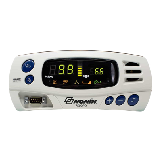
- Page 5 Figures Figure 1. Model 7500FO Front View ................6...
- Page 6 Tables Table 1. Symbols ....................... 4 Table 2. Factory Default Settings................12 Table 3. Basic Functions..................15 Table 4. Limits Display Sequence................15 Table 5. Advanced Functions .................. 16 Table 6. Electromagnetic Emissions................ 31 Table 7. Electromagnetic Immunity................32...
-
Page 7: Indications For Use
To avoid patient injury, use only Nonin-branded PureLight pulse oximeter sensors. These sensors are manufactured to meet the accuracy specifications for Nonin pulse oximeters. Using other manufacturers’ sensors can result in improper pulse oximeter performance. To prevent improper performance and/or patient injury, verify compatibility of the monitor, sensor(s), and accessories before use. -
Page 8: Cautions
To avoid injury or potential equipment damage, always keep the oximeter, battery charger and metal end of fiber optic cable beyond the distance of magnetic attraction. To ensure safe operation of the 7500FO in the MR environment, the monitor must be located outside the 200 Gauss line of the MR room and must be firmly attached to a fixed object. - Page 9 Follow local, state and national governing ordinances and recycling instructions regarding disposal or recycling of the device and device components, including batteries. Use only Nonin-approved battery packs. In compliance with the European Directive on Waste Electrical and Electronic Equipment (WEEE) 2002/96/EC, do not dispose of this product as unsorted municipal waste.
-
Page 10: Guide To Symbols
Guide to Symbols Guide to Symbols This table describes the symbols that are found on the Model 7500FO. Detailed information about functional symbols can be found in “Operating the Model 7500FO.” Table 1: Symbols Symbol Description Caution! Consult Instructions for Use. - Page 11 Guide to Symbols Table 1: Symbols (Continued) Symbol Description RoHS Compliant (China) Federal law (USA) restricts this device to sale by or on the order of a licensed practitioner. Protected against vertically falling water drops when enclosure is tilted up to IPX2 15 degrees, per IEC 60529.
-
Page 12: Displays, Indicators And Controls
Pulse Rate Display The pulse rate display is located on the right-hand side of the Model 7500FO front panel and is identified by the symbol. This display shows the pulse rate in beats per minute, from 18 to 321. -
Page 13: Indicators And Icons
This amber LED indicates when a sensor has become disconnected, has failed, or is not compatible with this monitor. NOTE: In the 7500FO, the Sensor Alarm LED latches. Sensor must be properly attached to patient and alarm silence button must be toggled to clear LED. -
Page 14: Model 7500Fo Front Panel Buttons
Model 7500FO Front Panel Buttons ON/STANDBY Button Pressing this button once turns on the Model 7500FO. Holding this button for at least 1 second shuts down the unit, putting it into Standby mode. In Standby mode, all device functions are shut off, with the following exceptions: •... - Page 15 Displays, Indicators and Controls Plus (+) and Minus (-) Buttons These buttons adjust values for many Model 7500FO functions. The Plus (+) and Minus (-) buttons are used to adjust time, date, volume and upper and lower alarm limits, except in Patient Security mode.
-
Page 16: Operating The Model 7500Fo
• Before using the Model 7500FO, the battery must be charged for four (4) hours. • When the Model 7500FO reaches critical battery, a medium priority alarm will sound. To clear the alarm: charge the battery and turn the device off and back on. -
Page 17: Operating Instructions
(1/4-20 thread) on the bottom of the device. • If interference is suspected to the MR image or to the 7500FO, contact Nonin Technical Service at (800) 356-8874, +1 (763) 553-9968, or +31 (0)13 - 79 99 040 (Europe) for assistance. -
Page 18: Operating Modes And Defaults
In Factory Defaults, all adjustable parameters are set as indicated in the table below. This is the Model 7500FO’s default operating setting. The Model 7500FO is shipped with factory defaults active. To revert to factory default alarm limits from the user-defined default alarm limits, simultaneously press the alarm silence and minus (-) buttons. -
Page 19: User-Defined Defaults
When the Model 7500FO is turned on in Patient Security mode, “SEC on” is displayed in the display area, and three informational tones sound. The upper alarm limits are then displayed, followed by the lower alarm limits. -
Page 20: Viewing And Changing Patient Security Mode
Operating Modes and Defaults Viewing and Changing Patient Security Mode Enter Patient Security Mode – With the device off, press and hold the Alarm Silence button while turning the device on. Exit Patient Security Mode – With the device off, press and hold the Alarm Silence and Limits buttons while turning the device on. -
Page 21: Operator Functions
Operator Functions Operator Functions The Model 7500FO has several easy-to-use basic functions. Most involve pressing only a single button. Table 3: Basic Functions Function Button Instruction Turn the Model Press the ON/STANDBY button to turn on the Model 7500FO on and off. -
Page 22: Table 5. Advanced Functions
The Model 7500FO features a number of advanced options, which are intentionally more difficult to activate. These functions are recommended only for trained operators and require multiple button presses to prevent accidental activation. - Page 23 Button Instruction NOTE: Alarm limits cannot be changed when the Model 7500FO is in Patient Security mode. Patient Security mode prevents accidental changes to critical parameters. The Model 7500FO allows users to lock and unlock alarm limits, volume settings, and time settings.
-
Page 24: Care And Maintenance
Nonin Technical Service. Field repair of the Model 7500FO circuitry is not possible. Do not attempt to open the Model 7500FO case or repair the electronics. Opening the case may damage the Model 7500FO and void the warranty. -
Page 25: Alarms And Limits
Alarms and Limits Alarms and Limits The Model 7500FO is equipped with audio and visual alarm indicators to alert the operator to provide immediate patient attention or to abnormal device conditions. The intended operator’s position for correctly perceiving a visual alarm signal and its priority is 1 meter (3.3 feet), per IEC 60601-1-8. -
Page 26: Alarm Summary
Alarms and Limits Alarm Summary The Model 7500FO detects both patient and equipment alarms. In general, patient alarms are identified as high priority, while equipment alarms are identified as medium priority. High priority alarms always take priority over medium priority alarms. Alarm indicators remain active for as long as the alarm condition is present. -
Page 27: Reviewing And Setting Volume And Alarm Limits
Reviewing and Setting Volume and Alarm Limits Reviewing and Setting Volume and Alarm Limits NOTE: Alarm limits reset themselves to default values each time the unit is powered up—unless the unit is in Patient Security mode. In Patient Security mode, alarm limits and volumes cannot be adjusted;... -
Page 28: Recalling Previous Settings
2. If the error persists, disconnect all power, and then reconnect the power and turn the unit back on. If the error still persists, note the error code and contact Nonin Technical Service at (800) 356-8874 (USA and Canada), +1 (763) 553-9968, or +31 (0)13 - 79 99 040 (Europe). -
Page 29: Memory And Data Output Features
Nonin, may be used to connect the Model 7500FO to the receiving computer. The information from the Model 7500FO is sent in an ASCII serial format at 9600 baud with 8 data bits, 1 start bit, and 2 stop bits. Each line is terminated by CR/LF. -
Page 30: Analog Output
Memory and Data Output Features Analog Output The Model 7500FO provides analog output signals for SpO , pulse rate, and event markers. Each output level conforms to the specifications shown below: Output Specification Output Analog Range 0 - 1.0 VDC (representing 0-100%) 1.27 VDC (out of track) -
Page 31: Memory Features
Playing back the data does not clear the data from memory. 1. With the unit off, connect the serial connector port of the Model 7500FO to the back of your computer using the 7500 SC cable, which is available from Nonin. -
Page 32: Connecting The Device Into A Medical System
Memory and Data Output Features Connecting the Device into a Medical System Incorporating the device into a medical system requires the integrator to identify, analyze, and evaluate the risks to patient, operators, and third parties. Subsequent changes to the medical system after device integration could introduce new risks and will require additional analysis. -
Page 33: Parts And Accessories
Parts and Accessories Parts and Accessories For more information about Nonin parts and accessories: • Contact your distributor or Nonin at (800) 356-8874 (USA and Canada), +1 (763) 553 9968, or +31 (0)13 - 79 99 040 (Europe). • Visit www.nonin.com. -
Page 34: Service, Support, And Warranty
Accordingly, any sign or evidence of opening the Model 7500FO, field service by non-authorized personnel, tampering, or any kind of misuse or abuse of the Model 7500FO, shall void the warranty in its entirety. All non-warranty work shall be done according to Nonin standard rates and charges in effect at the time of delivery to Nonin. -
Page 35: Troubleshooting
Model 7500FO will not The battery pack is not charged. Plug in the Model 7500FO AC Adapter to operate on batteries. charge the battery pack. The battery pack is inoperable. Contact Nonin Technical Service for repair or replacement. - Page 36 Contact your distributor or Nonin Technical Service for repair or replacement. If these solutions do not correct the problem, please contact Nonin Technical Service at (800) 356-8874 (USA and Canada), +1 (763) 553-9968, or +31 (0)13 - 79 99 040 (Europe).
-
Page 37: Technical Information
Accuracy, and Limit Alarm Conditions or generation of a Technical Alarm Condition. Accuracies or alarms may be affected as a result of exposure to electromagnetic disturbances that are outside of the environments listed in the Indications For Use. If issues are experienced, move Nonin system away from the source of electromagnetic disturbances. -
Page 38: Table 7. Electromagnetic Immunity
Technical Information Table 7. Electromagnetic Immunity Immunity Test Compliance Level This device is intended for use in the electromagnetic environment specified in the Indications For Use. Electrostatic Discharge (ESD) ±8 kV contact IEC 61000-4-2 ±15 kV air Electrical Fast Transient/Burst ±2 kV for power supply lines IEC 61000-4-4 ±2 kV for input/output lines... -
Page 39: Equipment Response Time
Technical Information Equipment Response Time If the signal from the sensor is inadequate, the last measured SpO and pulse rate values freeze for 10 seconds and are then replaced with dashes. Values Average Latency Standard/Fast Averaged SpO 4 beat exponential 2 beats Pulse Rate Values Response Latency... -
Page 40: Testing Summary
Specific to this example: • The response of the 4-beat average is 1.5 seconds. Testing Summary accuracy, and low perfusion testing were conducted by Nonin Medical, Inc., as described below: Accuracy Testing During motion and no-motion conditions at an independent research laboratory, SpO... -
Page 41: Principles Of Operation
Technical Information Principles of Operation Pulse oximetry is a non-invasive method that passes red and infrared light through perfused tissue and detects the fluctuating signals caused by arterial pulses. Well-oxygenated blood is bright red, while poorly oxygenated blood is dark red. The pulse oximeter determines functional oxygen saturation of arterial hemoglobin (SpO ) from this color difference by measuring the ratio of absorbed red and infrared light as volume fluctuates with each pulse. - Page 42 Technical Information Altitude (Operating): Up to 4,000 meters (13,123 feet) Hyperbaric Pressure: Up to 4 atmospheres Power Requirements: Mains: 100-240 VAC 50-60 Hz DC Input: 12 VDC 1.5A AC adapter (in MR use battery operation only) Internal Power: Battery: 7.2 volt NiMH battery pack Operating Life (fully charged battery): 30 hours minimum Operating Life (when using 5V, 250 mA accessory power supply [Pin 9]): 10 hours...
Need help?
Do you have a question about the 7500FO and is the answer not in the manual?
Questions and answers