Advertisement
OPERATING & MAINTENANCE MANUAL
WARNING: ALL OPERATING AND MAINTENANCE PROCEDURES SHOWN ON THE NEXT
PAGE OF THIS MANUAL MUST BE FOLLOWED DAILY FOR PROPER OPERATION OF
YOUR WASCOMAT MACHINE.
PLEASE ENTER THE FOLLOWING INFORMATION AS IT APPEARS ON THE MACHINE(S)
DATA PLATE(S).
MACHINE TYPE OR MODEL
MACHINE SERIAL NUMBER(S)
ELECTRICAL CHARACTERISTICS: ________ VOLTS, _______ PHASE, _______ HZ.
MAKE CERTAIN TO KEEP THIS MANUAL IN A SECURE PLACE FOR FUTURE
REFERENCE.
WASCOMAT SELECTA
S28/125
S28/185
471 1562-69/03
00.23
Advertisement
Chapters

Related Manuals for Wascomat Selecta S28/125


Summary of Contents for Wascomat Selecta S28/125
- Page 1 00.23 WARNING: ALL OPERATING AND MAINTENANCE PROCEDURES SHOWN ON THE NEXT PAGE OF THIS MANUAL MUST BE FOLLOWED DAILY FOR PROPER OPERATION OF YOUR WASCOMAT MACHINE. PLEASE ENTER THE FOLLOWING INFORMATION AS IT APPEARS ON THE MACHINE(S) DATA PLATE(S). MACHINE TYPE OR MODEL MACHINE SERIAL NUMBER(S) ELECTRICAL CHARACTERISTICS: ________ VOLTS, _______ PHASE, _______ HZ.
- Page 3 S28/185 WARNING: ALL OPERATING AND MAINTENANCE PROCEDURES SHOWN ON THE NEXT PAGE OF THIS MANUAL MUST BE FOLLOWED DAILY FOR PROPER OPERATION OF YOUR WASCOMAT MACHINE. PLEASE ENTER THE FOLLOWING INFORMATION AS IT APPEARS ON THE MACHINE(S) DATA PLATE(S). MACHINE TYPE OR MODEL MACHINE SERIAL NUMBER(S) ELECTRICAL CHARACTERISTICS: ________ VOLTS, _______ PHASE, _______ HZ.
- Page 4 To remove the top panel on models on which it is secured by one or two keylocks, use the keys originally shipped in the drum package. Be certain to relock after remounting the top panel. MANUFACTURED BY WASCATOR DISTRIBUTED BY WASCOMAT INWOOD, NEW YORK, USA 471 7662-02 LOCATED ON THE DOOR: WARNING !
- Page 5 Be sure to keep the machine(s) in proper working order: Follow all maintenance and safety procedures. Further information regarding machine safety, service and parts can be obtained from your dealer or from Wascomat through its Teletech Service Hotline - 516/371-0700.
-
Page 7: Table Of Contents
Wascomat Selecta S28/125 • S28/185 Contents Introduction ..............1 Technical data ..............2 Installation ................ 5 Safety rules ..............14 Operating instructions ............ 15 Mechanical and electrical design ........19 Maintenance ..............36 Trouble-shooting ............37 The manufacturer reserves the right to make changes to design and material specifications, without notifications. -
Page 8: Introduction
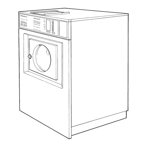
Introduction Introduction The Selecta 28 model washer/extractor has been developed to meet the Fig. heavy duty requirements of hotels, motels, nursing homes, hospitals, pro- fessional laundries, restaurants, airlines, ships, schools, colleges and all on-premises laundries where flexibility and quick formula variation, coupled with high quality automatic washing, are required. -
Page 9: Technical Data
Technical data Technical data Wascomat Selecta S28/125 Dry load capacity up to 35 lbs Overall dimensions Width 745 mm 29 5/16 in Depth (at the top) 915 mm 36 in Height 1196 mm 47 4/6 in Net weight 210 kg... - Page 10 Technical data Technical data Wascomat Selecta S28/185 Dry load capacity up to 50 lbs Overall dimensions Width 827 mm 32 9/16 in Depth (at the top) 960 mm 37 13/16 in Height 1315 mm 51 3/4 in Net weight 264 kg...
- Page 11 Technical data Outline and dimensions S28/125 S28/185 inches inches A 1196 47 1/16 1315 51 3/4 18 5/16 21 1/4 29 5/16 32 9/16 37 13/16 8 1/16 8 1/16 6 5/16 6 5/16 G 1040 40 15/16 1160 45 5/8...
-
Page 12: Installation
A template showing the size of the foundation and positioning of the foundation bolts can be provided by Wascomat. For installation on an existing concrete floor, the floor must be at least 8" thick and of good quality. - Page 13 Installation Mechanical installation • Before mounting the machine place wide steel Fig. shims on the concrete foundation over the steel bolts. shim • Lift the machine and lower it in position. Never use the door or the door handle to lift or lower the machine since this can damage the door and door interlock.
- Page 14 Installation Electrical installation All electrical installations are to be carried out by licensed personnel. Fig. Although the machines are fitted with a thermal overload in the motor windings a separate three- phase common-trip circuit breaker must be installed for all three-phase machines. For proper overcurrent protection, check the data plate at the rear of the machine.
- Page 15 Fig. 3/4" reinforced rubber hosing not to exceed 6 ft in length. Hang the hosing in a large loop. S28/125 Do not use rigid piping. Never force a hose onto the threads or you may cause cross-threading and leaks. If this occurs,...
- Page 16 NOTE To simplify installation, Wascomat has made available the following hose kits: 1833 For S28/125 – part. No. 002008 For S28/185 – part. No. 002009 These kits contain inlet hoses, drain hose, hose clamps and washers. Start-up and safety checklist...
- Page 17 Installation Installing top-mount manifold for connection of liquid supplies Remove the lid and lid support from over the soap box. Pull the manifold knobs up and forward. The Fig. small hinged lid shall be mounted towards the front. 1. Loosen both knobs so that one side of the Fig.
- Page 18 Installation 1. Drop the knob into the larger opening in the Fig. supply injector manifold. 2. Tighten securely. Do not overtighten! Do not use pliers or other tools to tighten the knobs! Fig. 1. Select the correct size rubber ring which will fit snugly on the chemical tube you are using.
- Page 19 IMPORTANT: Door safety interlock must be checked 1853 daily in accordance with above procedure. WARNING: Before servicing Wascomat equipment, disconnect electrical power. IMPORTANT: Le verrouillage de sûreté de la porte doit être vérifié tous les jours selon la procédure ci-dessus.
- Page 20 Fig. registration card, a copy of the warranty policy and other pertinent material. The warranty card should be completed and sent to Wascomat. All other items should be placed in a safe place for future reference. The machine should be cleaned when the instal-...
-
Page 21: Safety Rules
Safety rules Safety instructions • The machine is designed for water washing only. • The machine must not be used by children. • All installation operations are to be carried out by qualified personnel. Licensed personnel are necessary for all electric power wiring. -
Page 22: Operating Instructions
Operating instructions Fig. The keypad has seven program buttons, two programs option buttons and a combined start, pause and rapid advance button. A display panel with illuminated symbols shows the chosen program, the functions that have already occured, those still to occur, and the remaining wash time. If a fault occurs then indicators will refer the user to the fault list found under Service Information in this handbook. - Page 23 Operating Instructions Preparation Sort the wash according to the choices shown on the control panel. Check washing tips on garment labels. Make sure all pockets are empty and zips are closed. Open drum door, load articles and close door. Wash-program start •...
- Page 24 Operating Instructions Fig. • Press START. A clock dial will now appear in the display panel and two figures will show remaining wash time in minutes. A colon will flash for five minutes. The machine can be restarted during this time with no loss of detergent.
- Page 25 Operating Instructions Rapid Advance Phases of the program can be bypassed by using Rapid advance. Fig. • Hold the RAPID ADVANCE button depressed until the indicators have gone past the unwanted stages. Restarting If you discover, within five minutes of starting, that a wrong program has been selected, or that, for example a wrong garment has been put in with the wash, then the machine can be restarted without...
- Page 26 Mechanical and electrical design General The door and the electronic timer with display and program-selection buttons are fitted at the front of the machine. All control and indicating components, i.e. relays, level control, etc are assembled under the top cover, easily accessible at the top of the machine for simplified servicing.
- Page 27 Mechanical and electrical design Machine construction Outer shell The outer shell is made of heavy gauge surgical steel and is Fig. attached to a heavy duty, rigid head casting (back gable). The whole assembly is mounted on a heavy gauge fabricated steel base, galvanized for long life and corrosion resistance.
-
Page 28: Mechanical And Electrical Design
The extension of the bearing trunnion housing supports the rear bearing holding the shaft. A grease seals is mounted to prevent escape of grease. The bearings are permanently lubricated and need no maintenance. S28/125 C-clamp Rear bearing Bearing housing... - Page 29 Mechanical and electrical design Door NOTE The door consists of: a door skirt (1), door frame Fig. Do not attempt repair to a faulty (2), glass (3) and gasket (4). The skirt and door door lock. The individual frame are both made of enameled aluminium. The skirt is bolted directly to the outer shell of the components are not available.
-
Page 30: Control Unit
Mechanical and electrical design Control unit The keypad (1), includes all items necessary to operate the machine. Fig. These include an information display and wash cycle display window, control lights and selection buttons. The electronic timer is mounted just behind the control panel. Relays (2), transformer (3) and level control (4) are located at the top of the machine, easily accessible for service, as are the motor capacitors (5) on 1-phase models. - Page 31 Mechanical and electrical design Relays The S28 Selecta models employ three relays to Fig. energize the windings of the wash/extract motor. The relays control: • the reversing action of the motor at wash speed (1 and 2). • the action of the motor at extraction speed (3). Construction The body of the relay holding the stationary Fig.
- Page 32 Mechanical and electrical design Water level controls One pressure switch is used to control the correct water levels Fig. during various cycles of the washing program. Adjustment All pressure switches are factory-calibrated to meet specific requirements. The trip level for any one pressure switch can be changed only within narrow limits because each trip range requi- res a different set of springs.
-
Page 33: Drive Motor
Mechanical and electrical design Drive motor Description in general The motor is mounted on an axle with rubber Fig. dampeners. The V-belt is tightened by turning the motor on Fig. the axle and locking it in place using the tightener on the rear side of the motor. - Page 34 Principal wiring and points of measuring on single-phase motors. Fig. The numbers at the connection points refer to the terminal num- bers at the motor connector plug. The numbers in circles indicate points of ampere measurements. Fig. S28/125 208-240 V 60 Hz single-phase 1700...
- Page 35 Mechanical and electrical design S28/185 208-240 V 60 Hz single-phase 1791...
- Page 36 A burned out motor can be re-wound. NOTE Before connecting a separate overload protector consult the local code. Single-phase S28/125 and S28/185 machines are also equipped with a manually resettable 0304 overload protector mounted on the extract relay in the control unit. This overload protector protects the motor during the start-up of the extraction.
- Page 37 Mechanical and electrical design Inlet valves for S28/125 and detergent valve for S28/185 Construction Each valve has a single-inlet with either one, two or three outlets, each with its own solenoid coil. Fig. The body is made of heat-resistant polyamid plastic and the solenoids encased in water-tight plastic.
- Page 38 Mechanical and electrical design Repair instructions Limescale can block the hole in the valve diaph- ragm and interfere with the function of the valve. It is therefore advisable to dismantle and clean Fig. the valve at certain regular intervals. The fre- quency depends on operating conditions and the level of contamination in the water.
- Page 39 Mechanical and electrical design Inlet valve for S28/185 (from S/N 9508/011935) The water inlets have brass bodies with larger Fig. cross section of the outlet in order to achieve a shorter filling time for the machine. Construction Fig. The valve housing is made of pressed brass. The spring-loaded plunger is made of stainless steel and located at its lower end.
- Page 40 Mechanical and electrical design Inlet valve for S28/185 (up to S/N 9508/011934) The water inlets have brass bodies with larger Fig. cross section of the outlet in order to achieve a shorter filling time for the machine. Construction The valve housing is made of pressed brass. The spring-loaded plunger is made of stainless steel and located at its lower end is a rubber gasket for the pilot valve.
-
Page 41: Drain Valve
Mechanical and electrical design Drain valve Description Fig. The drain valve is steered using the pressure in the cold water intake. A hose (1) is connected between the cold water intake and a solenoid valve (2). When the solenoid valve is activated, it opens and allows water to flow into the feeder hose (3). - Page 42 Mechanical and electrical design Soap supply box The three-compartment soap supply box is located at the top of the machi- Fig. ne. Viewed from the front, the compartments marked with figures 1, 2 and 3 are used as follows: For liquid Supplies: Compartment 2 only is used in conjunction with a top mount supply manifold.
-
Page 43: Maintenance
Maintenance Maintenance Preventive maintenance has been reduced to a minimum by the careful design of reliable components and material. However, the following measures should be taken at regular intervals and in proportion to the hours of service. IMPORTANT! Make certain that all electrical power to the machine is shut off before removing top or rear panels. -
Page 44: Trouble-Shooting
Trouble shooting The purpose of the trouble-shooting guide is to facilitate the location and correction of the most common machine problems. Before the top panel is removed, power to the machine must be switched off at the main source or at the separate circuit breaker. At each trouble-shooting attempt, the plug in connectors on the control panel should be moved in and out in order to eliminate improper contact due to faulty connection. -
Page 45: Trouble Shooting
Trouble shooting Trouble shooting If the machine does not start Fig. A Check circuit breaker in the power feed line to the machine. B Check the door safety switches. C Check the glass cartridge fuses. D Check electrical auxiliary contact on extract relay. - Page 46 Trouble shooting If machine does not extract A Check extract relay and relay coil for proper Fig. operation. If the motor does not operate at wash speed A Check wash relays. Fig. B Check motor and V-belt. C Review procedures outlined under section "If machine does not start"...
- Page 47 Trouble shooting If machine runs slowly on wash speed or there is a slapping or thumping noise Fig. A Replace the V-belts. If a metallic noise can be heard at rear of machine Fig. A Tighten the pulley on the motor shaft. If the door is leaking Fig.
- Page 48 Trouble shooting If there is a leaking around the glass Fig. A Replace door gasket if worn. If water does not enter the machine A Check the valve coils on inlet valves. B Check wires leading to valve coils. Fig. C Be sure manual shut-off valves are in open position.
- Page 49 Trouble shooting If water continues to fill without stopping Fig. A Check hose attached to level control unit. B Check inlet valves for dirt underneath the valve diaphragm. To localize, shut off power. If water continues to flow, inlet valves have foreign material in them and should be thoroughly cleaned.
-
Page 50: Installation
Trouble shooting If machine vibrates excessively Fig. Tighten mounting bolts. Check that the shipping security has been remo- ved. Refer to mechanical installation, page 6. 1140... -
Page 51: Service Information
Service Information Service Information If there is a mains power failure the machines' Fig. memory will remember the selected program for about 8-10 minutes. The machine will restart automatically when power is restored. Program error is indicated by a number code in the display panel. - Page 52 Built in service program Built in service program In order to facilitate function checks or possible fault finding, a service program has been built into the machine. This program should only be used by qualified service personnel. Setting of service position •...
- Page 53 Built in service program Function checks The program indicator on the display window Fig. indicates certain inputs by lighting arrows. For example, arrow number 5 is lit when the door closes. This shows that the door's micro switch is operating correctly. The table below shows the inputs displayed by the program indicator.
- Page 54 Built in service program Code Function Detergent supply 1 Detergent supply 2 Detergent supply 3 Detergent supply 4 Detergent supply 5 Connection valve, hot water Connection valve, cold water Connection valve, hard water Heating (The temperature itself is shown in the display window, not the 19 code).
- Page 55 Fault-finding Circuit Board...
- Page 56 Fault-finding Fault-finding Contents PCB completely dead PCB functioning, but display dead Arrow 10 is not lit on display Wash program cannot be selected Machine will not start Machine displays error code 01E Machine displays error code 02E Machine displays error code 03E Machine displays error code 04E Machine displays error code 05E Machine displays error code 06E...
-
Page 57: Pcb Completely Dead
Fault-finding PCB completely dead Change control fuse Is control fuse OK? Change PCB Are fuses Each fuse's F1-F3 OK? VDR OK? Change fuse Are fuses Adjust fuse holder correctly fitted, with no play in holder? Is transformer Change transformer Are transformer connected for connections voltages OK? -
Page 58: Pcb Functioning, But Display Dead
Fault-finding PCB functioning, but display dead Change PCB Each fuse's Are fuses F2 VDR OK? and F3 OK? Change fuse Are fuses Adjust fuse holder correctly fitted, with no play in holder? Change transformer Is transformer Are transformer connections connected for voltages OK? correct voltage? -
Page 59: Arrow 10 Is Not Lit On Display
Fault-finding Arrow 10 is not lit on display Change PCB Does display show SE? Is the service Change setting of switch in program service switch position? Change PCB 95.08... -
Page 60: Wash Program Cannot Be Selected
Fault-finding Wash program cannot be selected Connect panel plate Are only some Is panel plate correctly buttons not correctly functioning? connected? Clean it Is connector clean? Change PCB Is cable connector for Rectify panel plate correctly fitted and clean? Change panel plate 95.08... -
Page 61: Machine Will Not Start
Fault-finding Machine will not start when start button is activated Does PCB Close door Is the door start up, but closed? nothing more happens? Are micro- Rectify microswitch switch and wiring or wiring for "door closed" Is edge Rectify edge connector connector on PCB OK? - Page 62 Fault-finding Continued from page 6 Is voltage Change door lock Is the door from programmer lock locking? to door lock absent? Is wiring Change wiring between programmer and door lock OK? Change PCB Are microswitch Rectify microswitch and wiring for or wiring "door locked"...
-
Page 63: Machine Displays Error Code 01E
Fault-finding Machine displays Required water level not reached within 10 min. error code 01E Turn on tap Is the tap on? Fault in coil, Voltage absent Can valves change coil at valve? open in SE? Is relay for Check and Check wiring and valve on PCB not clean filter... -
Page 64: Machine Displays Error Code 02E
Fault-finding Machine displays Microswitch "door closed" (S3) not closed when wash program in progress. In the error code 02E service program, closed microswitch is indicated by program indicator arrow 5 being lit. Close door and restart Is the door closed? Is microswitch Rectify/adjust in door OK? -
Page 65: Machine Displays Error Code 03E
Fault-finding Machine displays Fault or resistance too high in temperature sensor. Threshold value is approx. 17.4 k Ω error code 03E (-3 ° C). At 20 ° C the sensor's resistance is approx. 5.8 k Ω . Does sensor Change sensor have correct resistance? Change wiring... -
Page 66: Machine Displays Error Code 04E
Fault-finding Short-circuit or resistance too low in Machine displays temperature sensor.Threshold at approx. error code 04E 350 Ω (+98 ° C). Sensor resistance at 20 ° C is approx. 5.8 k Ω . Does sensor Change sensor have correct resistance? Is there a short-circuit between: Are all... -
Page 67: Machine Displays Error Code 05E
Fault-finding Machine displays Water level indicated right at start of program error code 05E Is machine Empty water and try empty of water again at start of program? Is dis- charge sy- Clean discharge stem free of system. For pump foreign matter machine, check also (clear passage... - Page 68 Fault-finding Continued from page 12 Is level hose Change level hose free of foreign matter? Is level hose Blow level hose clear free of drops of water? connections Does level to level control Clean control work clean and free of in SE? foreign matter? Change PCB...
-
Page 69: Machine Displays Error Code 06E
Fault-finding Machine displays Something wrong with machine EPROM. Code read from EPROM incorrect for some error code 06E reason. Is the machine Change EPROM EPROM turned and turn it the the right way? right way Are all the Rectify EPROM pins correctly in the holder? Is the EPROM... -
Page 70: Machine Displays Error Code 07E
Fault-finding Machine displays Machine heating water too slowly, less than 5 ° C in 20 min. error code 07E Can the relay Change PCB Is the relay on Is there a voltage operate in SE? the programmer supply? operating? Note! Note! •... -
Page 71: Machine Displays Error Code 08E
Fault-finding Machine displays Machine emptying too slowly, allocated time not sufficient to discharge water. error code 08E Does water flow have clear Rectify passage through pipe couplings and restrictors? Clean discharge discharge system. For pump system free of machine, check also foreign matter (clear pump housing (coins, passage for... - Page 72 Fault-finding Continued from page 16 Does drain Rectify, possibly by valve open fully/ changing valve/pump does pump rotate? Change level hose Is level hose free of foreign matter? Is level Blow level hose clear hose free of drops of water? Does level Change level control control work...
- Page 73 Fault-finding Continued from page 17 connections Clean to level control clean and free of foreign matter? Is there Change PCB water in machine at program start? Empty water and try again 95.08...
-
Page 74: Machine Displays Error Code 09E
Fault-finding The imbalance switch indicates imbalance Machine displays (closed microswitch) on changeover from wash error code 09E stage to drain stage. In the service program, closed microswitch is indicated by program indicator arrow 4 being lit. Is the sensing pin Rectify on the micro- switch positioned... -
Page 75: Machine Displays Error Code 10E
Fault-finding Machine displays Timer receives signal that the extraction error code 10E relay has operated, even though timer has given command for wash speed. This check takes place every time command for wash speed has been issued during wash stage (not during drain or extraction stages).
Need help?
Do you have a question about the Selecta S28/125 and is the answer not in the manual?
Questions and answers