Advertisement
Quick Links
Download this manual
See also:
User Manual
MAKING MODERN LIVING POSSIBLE
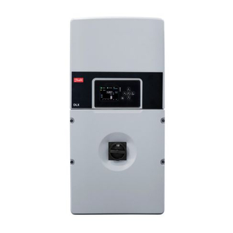
DLX
Installation Guide
DLX 2.0 UL - DLX 2.9 UL - DLX 3.8 UL - DLX 4.4 UL
SOLAR INVERTERS
Advertisement

Subscribe to Our Youtube Channel
Related Manuals for Danfoss DLX 2.0 UL


Summary of Contents for Danfoss DLX 2.0 UL
-
Page 1: Installation Guide
MAKING MODERN LIVING POSSIBLE Installation Guide DLX 2.0 UL - DLX 2.9 UL - DLX 3.8 UL - DLX 4.4 UL SOLAR INVERTERS... - Page 2 D Danfoss and the D Danfoss logo otype are reg gistered trad demarks of Danfoss A/S S. All rights r reserved. Copyright t ©: Danfoss, , 2012 es L00410624-0 Installation Gu uide DLX UL serie...
- Page 4 Installation Gu u ide DLX UL serie e s L00410624-0 01...
- Page 5 ntents Product O verview ....................... 6 1.1. arning Symbo ols ..........................6 1.2. oduct Label ............................6 1.3. npacking and d Inspection ......
- Page 7 Table 1 1.2: Symbols app earing on the pr oduct label Symb Description Discharge time e: High voltag es may be pre esent inside th e inverter for 1 1 hour after witch OFF Refer to User G Guide DLX UL series: The saf fety precautio ns and instruc...
- Page 16 2.3.2. . Overcu urrent Prot tection De evices Overc current prote ection devices s, fuses or ci rcuit breake ers, protect th he circuit con nductors and preve ent overheati ng as a result t of overload , short circuit t or ground fa ault.
- Page 19 The bra acket consists of three parts A. Inve erter Bracket B. Spac cer (Optional) C. Strin ngbox bracket Figure e 2.2: Wall brack ket components • The e bracket is de esigned to su upport 176.4 lbs. / 80 kg. •...
- Page 20 4. Ass semble the St tringbox brac cket (C) with the spacer (B B) by putting the spacer in nto the acket opening 5. Fas sten the spac cer by pulling g it over the s lit until it is fa astened.
- Page 22 2.6.1. . Connec ctions Are 1. CAN bus terminal 2. RS-4 485 terminal 3. Ethe ernet port 4. Inter rnal DC termin nal blocks, +POS S and -NEG 5. Inter rnal DC ground d terminal, GND/ D/PE 6. Inter rnal AC termin nal block 7.
- Page 23 Figure e 2.7: Hole cover rs on the Stringbo Figure 2.8 8: Removing the hole covers • Use e a 1” hole saw w to remove the knockou ts for the ” ” fittings and ” hole s saw to move the knoc ckouts for the e 1”...
- Page 24 NOTIC Follow t the guideline es from the co onduit manu ufacturer rega arding conne ection, ground ing and tight tening torque 2.6.3. . DC Term minals Figure e 2.10: DC termi nal blocks The in ncoming PV c conductors s hall be termi nated at the 1.Unground...
- Page 27 Nega ative Ground ed PV String Positiv ve Grounded P PV String Figure e 2.14: Negative grounded Figure 2. .15: Positive grou unded To ch hange from N Negative gro ound to Posi tive ground • Term minate the p ositive cond ductors at the e terminal blo...
- Page 33 2.6.7. . Networ rk Connec ctions The in nverter is equ uipped with t three commu unication inte erfaces: Ether rnet, CAN, an d RS-485. Ether rnet provides s communica ation betwee n the integra ated web serv ver and a com mputer, eithe direct tly connected...
- Page 34 NOTIC If multip ple inverters are connecte ed together, a all inverters m must be conn nected to the CAN bu us before Star rt Up to benef fit from singl e installation n setup. • Eth ernet: Use CA AT5 or better r, with size 24 4 AWG / 0.21...
- Page 35 • Be c careful not to o bend the pi ns when rem moving or inst talling the jum mper! Table 2 2.5: Jumper posit tion for the termi ination resistanc nection Area Jumpe er Position Pins The pins s are termina ated.
- Page 37 3. St tart Up This c chapter provi des instructio ons to ensure e a safe start- - up of the DL LX UL inverte rs. A minim mum voltage of 184V nd 230V nd a power g reater than 7 is requir red from the PV sys...
- Page 38 2. RS- -485 • Con nnecting the inverters via the RS-485 b bus enables c communicatio on with certa ain 3 party uipment. In an n RS-485 netw work, the 3 party equipm ment will act as a master, w while all inve erters will bec...
- Page 39 3.1.2 .2. LEDs There e are three LE EDs next to th he display scr reen. The upp per one is red d, the middle is yellow and the lo ower one is g reen. Table 3 3.1: LEDs. mbol Func ction Action...
- Page 40 3.1.3. . Start In nstallation At firs st power-up, and with suff ficient AC po o wer, the disp play shows th he Start Instal llation screen 1. Sta Left – – Cancel Right t – Ok Enter r – Confirm 2.
- Page 41 4. Tim HH.M M (24 H) Enter r – Call up the d date Up – I Increase prese ent digit Down n – Decrease p resent digit Left – – Select previo us digit Right t – Select next digit Enter r –...
- Page 42 6. Ma aster Unit Defau ult – No Enter r – Call up the o options Up – Y Down n – No Enter r – Confirm Left – – Back Right t – Next Enter r – Confirm If the inverter is se et to master, d data must be...
- Page 43 Instal ller password d, which may only be obta ained for instal lers and grid operators by y contacting D Danfoss. • The se elected grid c configuration n must match h that on the actual install lation site; otherw...
- Page 45 10. Si Enter r – Call up the k keyboard The ke eyboard enab bles typing of a a site name. Left – – Back Right t – Next Enter r – Confirm 11. U nit Name Enter r – Call up the keyboard The u unit name help...
- Page 46 13. O Owner Passw word Enter r – Call up the d digits Defau ult – 0003. Chang ge the passwo ord to 4 option nal digits Left – – Back Right t – Finish Enter r – Confirm NOTIC With se veral inverte rs connected...
- Page 47 4. Co onnec tion b etwee en Inve erter a nd PC The s ite performan nce can be ch hecked remo otely by using g a computer r. The connec ction can be achie ved between n the inverter r and the com mputer either r directly or v...
- Page 48 5. In nternal l Web Server The in nverter has a n internal, on nboard web S Server provid ding detailed information about the opera ation, warnin g/alarms and d energy prod duction from m the inverter/ /plant. • The e web page is s best viewed d in Firefox 6.0...
- Page 49 6. Tr rouble eshoot ting This c chapter conta ains useful inf formation if t the inverter m malfunctions s during start- -up or opera ation. Start by y checking th hat the install ation is carrie ed out correc ctly,and the d display inform...
- Page 50 Table 6 6.1: Description o of messages appe earing in the disp play during inver rter failure Disp play Message Description Action Pane el fault (W/A – E01) PV module fai ilure - Contact the supplier* Inpu t circuit break er open (A DC switch is o open...
- Page 51 Disp play Message Description Action Failu ure on AC side (W/A – Inverter failur e on the AC - Failure o on the AC side . Other W/A E11) side are also shown - If the inv verter is in Shu utdown, turn off the A AC side and the...
- Page 52 Disp play Message Description Action Micro oprocessor fau ult (W/A – - If the inv verter is in Shu utdown, turn E20) off the A AC side and the en the DC side. Wa ait for 30 secon nds, then turn on the A AC side and the en the DC side...
- Page 53 Disp play Message Description Action Grid fault, still runn ning (W – Fault ride-thro ough - Contact the supplier* E28) - Contact fault DC side ( (W – E29) The varistors o on the DC side the supplier fo or new parts are damaged.
- Page 54 D DLX UL series. Danfoss is co ommitted to i its policy of e environmenta respo onsibility, and d therefore ap ppeals to end...
- Page 56 Integral D DC switch PV ground ding Field configurable e for ungrounded d, positive & negat tive grounded Topology High fre equency transform mer, galvanic isola ation Performa nce monitoring Graph hical colour displa ay with 6 touch se nse buttons, 3x LE EDs for visual stat indication, Build- in Web Server...
- Page 57 8.2. F Field Ad djustab le Trip L Levels Table 8 8.1: 208Vac Trip D Details VALUE DEFAUL LT SETTING MIN. LEVE X. LEVEL ACCURACY Vac Over voltage 47.1 V 208.0 V 47.1 V ±2.5V high trip level Vac Over voltage 20 ms 50 ms...
- Page 59 Danfoss can accept no responsibility for possible errors in catalogues, brochures and other printed material. Danfoss reserves the right to alter its products without notice. This also applies to products already on order provided that such alterations can be made without subsequential changes being necessary in specifications already agreed.
Need help?
Do you have a question about the DLX 2.0 UL and is the answer not in the manual?
Questions and answers