Table of Contents
Advertisement
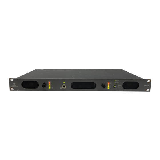
VMDA Series
(VMDA-1 and VMDA-4)
1U Monitor Speaker Unit with 1 or 4
AES/EBU Digital Inputs, 1 or 4 Analog
Stereo Inputs, Selected Analog Outputs,
Speaker Muting, Headphone Output,
Phase Indication, and Level Meters
Document P/N 821115 Rev-D
Title and Contents ...........................................................
Important Safety Instructions and Introduction ............................
Installation ..................................................................................
Description and Features ...........................................................
General Specifications ...............................................................
Section 1: Operation ......................................................
Front Panel Controls and Indicators ...........................................
Rear Panel Connectors and Settings ............................................
Section 2: Technical Information .............................
Service and Troubleshooting Guide ............................................
Main PCB Circuit Description ....................................................
VMDA-1 and VMDA-4 Block Diagrams ...................................
User Manual
CONTENTS
1
2
3
4
5
7
8
12
15
16
16
18
Advertisement
Table of Contents

Related Manuals for Wohler VMDA-1


Summary of Contents for Wohler VMDA-1
-
Page 1: Table Of Contents
General Specifications ............... Section 1: Operation ............Front Panel Controls and Indicators ........... Rear Panel Connectors and Settings ..........Section 2: Technical Information ......Service and Troubleshooting Guide ..........Main PCB Circuit Description ............ VMDA-1 and VMDA-4 Block Diagrams ........ - Page 2 Introduction Congratulations on your selection of a Wohler Technologies VMDA Series audio monitor unit. We are confident it represents the best performance and value available, and we guarantee your satisfaction with it. If you have questions or comments you may contact us at: Wohler Technologies, Inc.
-
Page 3: Installation
The universal AC input (100-240VAC, 50/60Hz) switching power supply is a self-resetting sealed type, with automatic over-voltage and over-current shutdown . There is no user-replaceable fuse in either the primary or secondary circuit. © 2006 Wohler Technologies Inc. ALL rights reserved... - Page 4 The single-rackspace VMDA series monitors permit selectable monitoring of from one to four stereo analog or four AES audio sources, with excellent full-range fidelity far exceeding that of an ordinary monitor. The VMDA-1 monitors one stereo analog or AES audio source while the VMDA-4 can monitor up to four stereo analog or AES audio sources.
-
Page 5: General Specifications
Units are certified to meet, at time of manufacture, all currently applicable product safety and EMC requirements, such as those of UL and CE. 0 dbV ref. 0.775V RMS. Features and specifications subject to improvement without notice. © 2006 Wohler Technologies Inc. ALL rights reserved... - Page 6 VMDA Series User Manual P/N 821115 Rev-C.5 (This page left intentionally blank) © 2006 Wohler Technologies Inc. ALL rights reserved...
-
Page 7: Section 1: Operation
VMDA Series User Manual P/N 821115 Rev-C.5 Section 1: Operation Front Panel Controls and Indicators Rear Panel Connectors and Settings © 2006 Wohler Technologies Inc. ALL rights reserved... - Page 8 Mute: To mute the speakers at any time, the button is briefly tapped once, the button blinks to indicate it is in mute mode. A second single tap unmutes the speakers. (Continued) © 2006 Wohler Technologies Inc. ALL rights reserved...
- Page 9 VMDA Series User Manual P/N 821115 Rev-C.5 VMDA-1 Front Panel VMDA-4 Front Panel Figure 1a.- VMDA Front Panel Controls and Indicators © 2006 Wohler Technologies Inc. ALL rights reserved...
- Page 10 While it is normal for stereo signals to contain some intermittant instanateous out-of-phase and in- phase conditions (small LEDs), a steady red glow of the larger center LED almost always indicates an out-of- phase alarm condition. (Continued) © 2006 Wohler Technologies Inc. ALL rights reserved...
- Page 11 VMDA Series User Manual P/N 821115 Rev-C.5 VMDA-1 Front Panel VMDA-4 Front Panel Figure 1a.- VMDA Front Panel Controls and Indicators © 2006 Wohler Technologies Inc. ALL rights reserved...
- Page 12 These Phoenix style, Mini-Combicon, dual vertical, 6-position terminal block connectors receive standard analog stereo signals. On the VMDA-4, there are a total of four (4) connectors while on the VMDA-1 there is one connector. Each connector has two inputs, with three positions per input. For each connector, the top three positions are the left input;...
- Page 13 VMDA Series User Manual P/N 821115 Rev-C.5 VMDA-1 Front Panel VMDA-4 Front Panel Figure-1b. VMDA Rear Panel Connectors and Settings © 2006 Wohler Technologies Inc. ALL rights reserved...
- Page 14 VMDA Series User Manual P/N 821115 Rev-C.5 (This page left intentionally blank) © 2006 Wohler Technologies Inc. ALL rights reserved...
-
Page 15: Section 2: Technical Information
VMDA Series User Manual P/N 821115 Rev-C.5 Section 2: Technical Information Service and Toubleshooting Guide Audio Circuit Description Interconnect Block Diagram © 2006 Wohler Technologies Inc. ALL rights reserved... -
Page 16: Service And Troubleshooting Guide
(IC22) by the transistor Q4. 5) IC15 can reset the codec by toggling pin 16. The codec is controlled by IC15’s serial port. The serial control lines are on pins 15, 18, 23 and 24. (Continued) © 2006 Wohler Technologies Inc. ALL rights reserved... - Page 17 P2 and P3 are used to adjust the signal to the correct level for the codec (IC20). Refer to the interconnect block diagrams on he following pages, for assistance in tracing the signal path through the detailed schematic. © 2006 Wohler Technologies Inc. ALL rights reserved...
- Page 18 VMDA Series User Manual P/N 821115 Rev-C.5 VMDA-1 Block Diagram © 2006 Wohler Technologies Inc. ALL rights reserved...
- Page 19 VMDA Series User Manual P/N 821115 Rev-C.5 VMDA-4 Block Diagram © 2006 Wohler Technologies Inc. ALL rights reserved...
- Page 20 Technologies, Inc. Phone: (510) 589-5676 31055 Huntwood Avenue Fax: (510) 870-0811 Hayward, CA 94544 US Toll-Free: 1-888-596-4537 web: www.wohler.com Phone: (510) 870-0810 e-mail: support@wohler.com Fax: (510) 870-0811 US Toll-Free: 1-888-596-4537 www.wohler.com support@wohler.com © 2006 Wohler Technologies Inc. ALL rights reserved...
Need help?
Do you have a question about the VMDA-1 and is the answer not in the manual?
Questions and answers