Table of Contents
Advertisement
Quick Links
VMQ Series
VMQ-4 / VMQ-2D / VMQ-SDI
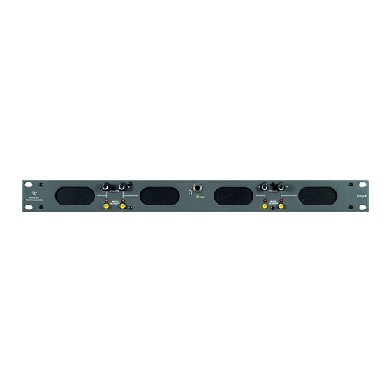
1U Monitor Speaker Unit with 4 Analog Inputs
or 2 AES/EBU Inputs or 1 SDI Input, with
4 Analog Outputs, 4 Separate Volume Controls
w/mutes, and 4 Signal Indication LEDs
Document P/N 821504 Rev-D
Title and Contents ...............................................................
Introduction .................................................................................
Section 1: Features and Specifications...................
Description and Features .............................................................
Applications, Specifications, and Rear Panel Configurations ...........
Section 2: Operation .........................................................
Installation ...................................................................................
Front Panel Features ...................................................................
Rear Panel Features ....................................................................
Section 3: Technical Information ..............................
General Mechanical Observations ................................................
Audio Circuit Description ............................................................
Interconnect Block Diagrams .......................................................
© 2006 Wohler Technologies Inc. ALL rights reserved
User Manual
CONTENTS
1
2
3
4
5
7
8
10
12
15
16
16
17
1
Advertisement
Table of Contents

Related Manuals for Wohler VMQ-4


Summary of Contents for Wohler VMQ-4
-
Page 1: Table Of Contents
Applications, Specifications, and Rear Panel Configurations ... Section 2: Operation ............Installation ................... Front Panel Features ..............Rear Panel Features ..............Section 3: Technical Information ......General Mechanical Observations ..........Audio Circuit Description ............Interconnect Block Diagrams ............© 2006 Wohler Technologies Inc. ALL rights reserved... -
Page 2: Introduction
Introduction Congratulations on your selection of a Wohler Technologies VMQ Series audio monitor unit. We are confident it represents the best performance and value available, and we guarantee your satisfaction with it. If you have questions or comments you may contact us at: Wohler Technologies, Inc. - Page 3 VMQ Series User Manual P/N 821504 Rev-D Section 1 General Features and Specifications Description Features Applications Specifications Rear Panel Configurations © 2006 Wohler Technologies Inc. ALL rights reserved...
-
Page 4: Section 1: Features And Specifications
A separate volume control is provided for each of the four monitored channels. Also, each channel has an LED, which illuminates when a signal is "active" in that channel. This allows the operator to easily determine which VMQ-4 channels are currently active, and is very helpful when quick volume adjustments are required. Separate mute buttons are provided for each channel. - Page 5 Units are certified to meet, at time of manufacture, all currently applicable product safety and EMC requirements, such as those of UL and CE. 0 dbV ref. 0.775V RMS. Features and specifications subject to improvement without notice. © 2006 Wohler Technologies Inc. ALL rights reserved...
- Page 6 VMQ Series User Manual P/N 821504 Rev-D (This page left intentionally blank) © 2006 Wohler Technologies Inc. ALL rights reserved...
-
Page 7: Section 2: Operation
VMQ Series User Manual P/N 821504 Rev-D Section 2 Operation Installation Front Panel Features Rear Panel Features © 2006 Wohler Technologies Inc. ALL rights reserved... - Page 8 The internal circuitry common is connected to the chassis. In the VMQ-4 (standard analog inputs), unbalanced sources may also be applied to the balanced inputs. For analog input signals, the gain is 6 dB greater with a single-ended source connected across both “hot”...
-
Page 9: Audio Connections
1) The internal circuitry common is connected to the chassis. 2) If RCA phono inputs (unbalanced) were ordered for the VMQ-4 unit, they have approximately 12dB more gain than the XLR (balanced) connectors for use with equipment which has "consumer" line level outputs (-10 to-15 dBv). - Page 10 The Power Indicator LED signals the operating condition of the power supply. The LED glows green to indicate the VMQ-4 is connected to mains power and an operation voltage is present. AES/EBU Signal Indication - Red/Green Bi-color LED (VMQ-2D Only) These two LEDs each glow green to indicate the presence of valid AES/EBU signals (one for each of two inputs) and each will glow red to indicate the absence of such signals in the associated input.
- Page 11 VMQ Series User Manual P/N 821504 Rev-D Section 2: Operation Figure-2a: VMQ Series Front Panel Features © 2006 Wohler Technologies Inc. ALL rights reserved...
- Page 12 (100K Ohm) connections. Either Phoenix (standard) or XLR (optional) connectors may be specified at the time of ordering the VMQ-4. Inputs are labeled 1 through 4. XLR connectors are 3-pin female and Phoenix Connectors are standard 3-pin type. Pin-out information for Phoenix connectors are silk-screened above each connector.
- Page 13 VMQ Series User Manual P/N 821504 Rev-D Section 2: Operation Figure-2b: VMQ Series Rear Panel Features © 2006 Wohler Technologies Inc. ALL rights reserved...
- Page 14 VMQ Series User Manual P/N 821504 Rev-D (This page left intentionally blank) © 2006 Wohler Technologies Inc. ALL rights reserved...
-
Page 15: Section 3: Technical Information
General Mechanical Observations Main Audio PCB - General Ciurcuit Description VMQ-4 System Block Diagram VMQ-2D System Block Diagram VMQ-SDI System Block Diagram NOTE: PCB layout and schematic support documentation is available upon request. © 2006 Wohler Technologies Inc. ALL rights reserved... -
Page 16: Audio Circuit Description
C10/R9-R11 filter any high-level low frequency transients, which might otherwise affect Q1 and Q2. Note that for this sensing circuit to work, the headphones MUST have a DC resistance not greater than about 1K ohm. © 2006 Wohler Technologies Inc. ALL rights reserved... - Page 17 VMQ Series User Manual P/N 821504 Rev-D Section 3: Tecnical Information VMQ-4 - System Block Diagram © 2006 Wohler Technologies Inc. ALL rights reserved...
- Page 18 VMQ Series User Manual P/N 821504 Rev-D Section 3: Tecnical Information VMQ-2D - System Block Diagram © 2006 Wohler Technologies Inc. ALL rights reserved...
- Page 19 VMQ Series User Manual P/N 821504 Rev-D Section 3: Tecnical Information VMQ-SDI - System Block Diagram © 2006 Wohler Technologies Inc. ALL rights reserved...
- Page 20 Technologies, Inc. Phone: (510) 589-5676 31055 Huntwood Avenue Fax: (510) 870-0811 Hayward, CA 94544 US Toll-Free: 1-888-596-4537 Phone: (510) 870-0810 web: www.wohler.com Fax: (510) 870-0811 e-mail: support@wohler.com US Toll-Free: 1-888-596-4537 www.wohler.com support@wohler.com © 2006 Wohler Technologies Inc. ALL rights reserved...
Need help?
Do you have a question about the VMQ-4 and is the answer not in the manual?
Questions and answers