Table of Contents
Advertisement
AMP1-VS and AMP1-VSA
1U Digital Audio Speaker Monitors
with One SDI Input and One SDI Output on BNC, Four Analog
Outputs (From SDI Input) on Phoenix, Four Analog Inputs
on Phoenix (-VSA Only), Two Analog Outputs of the
Left/Right Channel Selections on XLR, Summable Channel
Assignment, Four 26-Segment Level Meters, and Phase Indication
Title and Contents ..............................................................
Important Safety Instructions and Introduction ..................................
Description and Features .................................................................
Applications and Specifications ........................................................
Installation ......................................................................................
Section 2: Operation ........................................................
Front Panel Features ...................................................................
Rear Panel Features ....................................................................
Audio Amplifier and Speaker Configuration ................................
Section 3: Technical Information ................................
General Technical Observations ..................................................
SDI to Analog Converter Module PCB (919068) ..........................
SDI D/A Gain Calibration Fine Adjustment (919068) ...................
Level Meter Rear Panel 6-Position DIP Switch Settings ................
Level Meter Internal 10-Position DIP Switch Settings ..................
Level Meter DIP Switch Locations ...............................................
Level Meter Alternative Scales ....................................................
AMP1-VS Interconnect Block Diagram ........................................
AMP1-VSA Interconnect Block Diagram .....................................
© 2006 Wohler Technologies Inc. ALL rights reserved
Document P/N 821613 Rev-B
User Manual
CONTENTS
1
2
3
4
5
6
7
8
10
14
15
16
17
18
19
20
21
22
23
24
1
Advertisement
Table of Contents

Related Manuals for Wohler AMP1-VS


Summary of Contents for Wohler AMP1-VS
-
Page 1: Table Of Contents
Level Meter Rear Panel 6-Position DIP Switch Settings ....Level Meter Internal 10-Position DIP Switch Settings ....Level Meter DIP Switch Locations ..........Level Meter Alternative Scales ............ AMP1-VS Interconnect Block Diagram ........AMP1-VSA Interconnect Block Diagram ........© 2006 Wohler Technologies Inc. ALL rights reserved... - Page 2 Introduction Congratulations on your selection of a Wohler Technologies product. We are confident it represents the best performance and value available, and we guarantee your satisfaction with it. If you have questions or comments you may contact us at: Wohler Technologies, Inc.
-
Page 3: Section 1: Features, Specs, And Installation
AMP1-VS and AMP1-VSA User Manual P/N 821613, Rev-B Section 1 Features, Specs, and Installation Description Features Applications Specifications Installation © 2004 Wohler Technologies Inc. ALL rights reserved... - Page 4 The rear panels of both the AMP1-VS and AMP1-VSA feature one SDI input and one SDI output on unbalanced BNC connectors, four analog outputs (de-embedded from the SDI source) on four Phoenix connectors, and left and right analog outputs (of the channels assigned to the left and right speakers) on two balanced XLR connectors.
- Page 5 The AMP1-VS and AMP1-VSA are ideally suited for use in VTR bays, mobile production vehicles, teleconferencing installations, multimedia systems, satellite links and cable TV facilities, and on-air radio studios. Designed and manufactured in the U.S., the AMP1-VS and AMP1-VSA are backed by a strong warranty and a satisfaction guaranteed return policy.
-
Page 6: Installation
Connection of the audio feeds is straightforward. Please refer to the system interconnect block diagrams on pages 23 and 24 for clarification of the general signal paths into and out of the AMP1-VS and AMP1-VSA units. Care should be exercised to avoid mismatched cable types and other similar causes of undesired reflections in RF signal systems. -
Page 7: Section 2: Operation
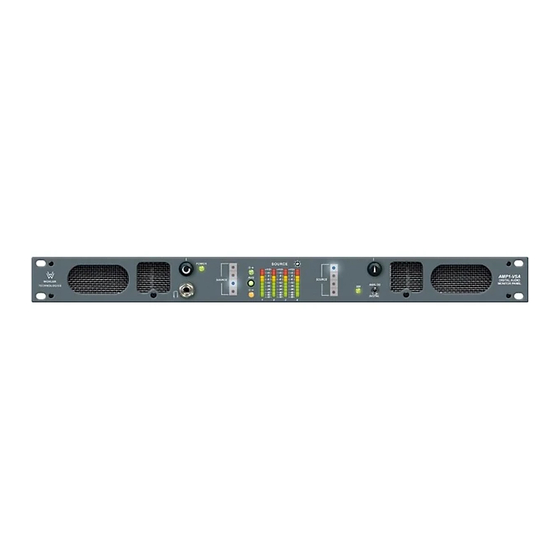
AMP1-VS and AMP1-VSA User Manual P/N 821613, Rev-B Section 2 Operation Front Panel Features Rear Panel Features Audio Amplifier and Speaker Configuration Balance Control Characteristics © 2004 Wohler Technologies Inc. ALL rights reserved... - Page 8 Section 2: Operation Front Panel Features Please refer to Figure-2a on the facing page to familiarize yourself with the front panel features of the AMP1-VS and AMP1-VSA units. The following sections describe these features and are referenced, by number, to Figure-2a.
- Page 9 AMP1-VS and AMP1-VSA User Manual P/N 821613, Rev-B Section 2: Operation AMP1-VS AMP1-VSA Figure-2a: Front Panel Features © 2004 Wohler Technologies Inc. ALL rights reserved...
- Page 10 AMP1-VS and AMP1-VSA User Manual P/N 821613, Rev-B Section 2: Operation Front Panel Features (Continued) Phase Indication LEDs These three LEDs indicate the instantaneous and average phase (polarity) conditions between the source(s) assigned to the left speaker channel and the source(s) assigned to the right speaker channel. The larger LED labeled AVG indicates the average phase condition between the left and right speaker channels.
- Page 11 AMP1-VS and AMP1-VSA User Manual P/N 821613, Rev-B Section 2: Operation AMP1-VS AMP1-VSA Figure-2a: Front Panel Features © 2004 Wohler Technologies Inc. ALL rights reserved...
- Page 12 Section 2: Operation Rear Panel Features Please refer to Figure-2b on the facing page to familiarize yourself with the rear panel features of the AMP1-VS and AMP1-VSA unit. The following sections describe these features and are referenced, by letter, to Figure-2b.
- Page 13 AMP1-VS and AMP1-VSA User Manual P/N 821613, Rev-B Section 2: Operation AMP1-VS AMP1-VSA Figure-2b: Rear Panel Features © 2004 Wohler Technologies Inc. ALL rights reserved...
- Page 14 AMP1-VS and AMP1-VSA User Manual P/N 821613, Rev-B Section 2: Operation Audio Amplifier and Speaker Configuration General Description All models in the AMP Series contain high performance transducers (speakers) driven by three power amplifiers; two amplifier/ driver combinations handle midrange and high frequency information in the left and right (stereo) speaker channels, while the third amplifier channel sums the left and right channel information below the 500 Hz crossover point in the two woofer (bass) speakers.
-
Page 15: Section 3: Technical Information
AMP1-VS and AMP1-VSA User Manual P/N 821613, Rev-B Section 3 Technical Information General Technical Observations SDI to Analog Converter Module PCB (919068) SDI D/A Gain Calibration Fine Adjustment (919068) Level Meter Rear Panel 6-Position DIP Switch Settings Level Meter Internal 10-Position DIP Switch Settings... - Page 16 AMP1-VS and AMP1-VSA User Manual P/N 821613, Rev-B Section 3: Technical Information General Technical Observations General Mechanical Observations Elimination of cabinet and component sympathetic vibrations (resonances) requires considerable attention to mechanical details. Because of this, and the physical constraints of the speaker’s acoustic enclosures, even minor changes to any of the mechanical details of the unit can seriously impair its acoustic performance.
- Page 17 The 919068 demultiplexes (extracts) the audio data from the video data, and converts it to analog. In the AMP1-VS and AMP1-VSA models, SDI channels one and two (first subgroup) and channels three and four (second subgroup) from Group I.D. #1 are demuxed for conversion to analog. Access to SDI Group I.D. #2, #3, or #4 is optional and may be specified at the time of order.
- Page 18 AMP1-VS and AMP1-VSA User Manual P/N 821613, Rev-B Section 3: Technical Information SDI D/A Gain Calibration Fine Adjustment (919068 PCB) The digital gain calibration is set at the factory for +4 dB (analog) = -20 dBFS (digital). Three other values (+8 = -20, +6 = -9, and 0 = -18) may also be user selected via a DIP switch on the rear panel (Item C, page 12).
- Page 19 AMP1-VS and AMP1-VSA User Manual P/N 821613, Rev-B Section 3: Technical Information Level Meter Rear Panel 6-Position DIP Switch Settings Line Level (Auto) Calibration, Reference Level, and Display Mode This 6-section DIP switch sets the Line Level Calibration, Reference Level, and PPM/VU Display Mode. See below.
- Page 20 (a special option specified at time of order) or by removing power and then reapplying power to the unit (unplug/replug power cord). Contact Wohler Technologies for more information about this feature. Contact Wohler Technologies for information about custom scales.
- Page 21 AMP1-VS and AMP1-VSA User Manual P/N 821613, Rev-B Section 3: Technical Information Level Meter DIP Switch Locations Rear Panel Level Meter 6-Position DIP Switch Module (see page 19) 919174 PCB Internal Level Meter 10-Position DIP Switch Module (see page 20)
- Page 22 Level Meter Alternative Scales The standard scale used on the level meters (26-segment) for the AMP1-VS and AMP1-VSA units is the Extended VU scale (see diagram below). However, if alternative scale characteristics are selected for the level meters using the Level Meter Internal 10-Position DIP Switch (page 20), it is recommended that a label with the appropriate scale be applied to the front panel LED bargraph level meters.
- Page 23 AMP1-VS and AMP1-VSA User Manual P/N 821613, Rev-B Section 3: Technical Information © 2004 Wohler Technologies Inc. ALL rights reserved...
- Page 24 AMP1-VS and AMP1-VSA User Manual P/N 821613, Rev-B © 2004 Wohler Technologies Inc. ALL rights reserved...
- Page 25 AMP1-VS and AMP1-VSA User Manual P/N 821613, Rev-B Notes: NOTE: PCB layout and schematic support documentation is available upon request. Wohler Technologies, Inc. Wohler Technologies, Inc. 31055 Huntwood Avenue 31055 Huntwood Avenue Hayward, CA 94544 Hayward, CA 94544 Phone: (510) 589-5676 Fax: (510) 870-0811...
- Page 26 AMP1-VS and AMP1-VSA User Manual P/N 821613, Rev-B Wohler Technologies, Inc. Wohler Technologies, Inc. 31055 Huntwood Avenue 31055 Huntwood Avenue Hayward, CA 94544 Hayward, CA 94544 Phone: (510) 589-5676 Phone: (510) 870-0810 Fax: (510) 870-0811 Fax: (510) 870-0811 US Toll-Free: 1-888-596-4537 US Toll-Free: 1-888-596-4537 www.wohler.com support@wohler.com...
Need help?
Do you have a question about the AMP1-VS and is the answer not in the manual?
Questions and answers