Table of Contents
Advertisement
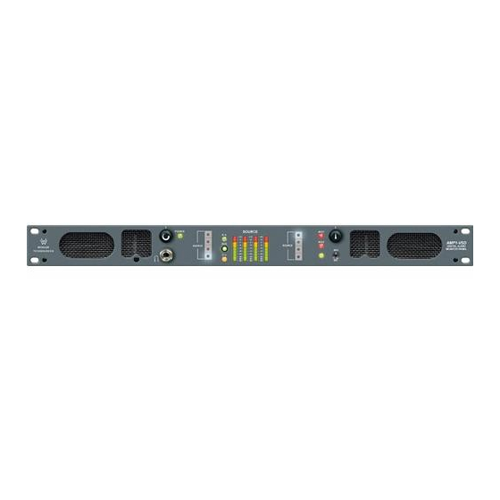
1U Digital Audio Speaker Monitors
with One SDI Input and One SDI Output on BNC,
Two AES Inputs on BNC, Two AES Outputs From SDI
Input on BNC, Two Analog Outputs of the Left/Right Channel
Selections on XLR, Four Analog Outputs From Selected
Digital Source, Summable Channel Assignment,
Four 26-Segment Level Meters, and Phase Indication
Title and Contents .............................................................
Introduction ...............................................................................
Section 1: Features, Specs, and Installation ...........
Description and Features .............................................................
Applications and Specifications ...................................................
Installation .................................................................................
Section 2: Operation ........................................................
Front Panel Features ...................................................................
Rear Panel Features ....................................................................
Audio Amplifier and Speaker Configuration ................................
Section 3: Technical Information ................................
General Technical Observations ..................................................
AES to Analog Converter Module (919050 PCB) .........................
AES Error Indication Jumper Locations (919050 PCB) .................
SDI to AES Converter Module (919096 PCB) ..............................
Level Meter Rear Panel 6-Position DIP Switch Settings ................
Level Meter Internal 10-Position DIP Switch Settings ..................
Level Meter DIP Switch Locations (919174 PCB) .........................
Level Meter Alternative Scales ....................................................
AMP1-VSD Interconnect Block Diagram .....................................
© 2004 Wohler Technologies Inc. ALL rights reserved
AMP1-VSD
Document P/N 821615 Rev-A
User Manual
CONTENTS
ECO-2784 (11/17/04)
1
2
3
4
5
6
7
8
12
16
17
18
19
20
21
22
23
24
25
26
27
1
Advertisement
Table of Contents

Related Manuals for Wohler AMP1-VSD


Summary of Contents for Wohler AMP1-VSD
-
Page 1: Table Of Contents
Level Meter Rear Panel 6-Position DIP Switch Settings ....Level Meter Internal 10-Position DIP Switch Settings ....Level Meter DIP Switch Locations (919174 PCB) ......Level Meter Alternative Scales ............ AMP1-VSD Interconnect Block Diagram ........ECO-2784 (11/17/04) © 2004 Wohler Technologies Inc. ALL rights reserved... -
Page 2: Introduction
Introduction Congratulations on your selection of a Wohler Technologies product. We are confident it represents the best performance and value available, and we guarantee your satisfaction with it. If you have questions or comments you may contact us at: Wohler Technologies, Inc. -
Page 3: Section 1: Features, Specs, And Installation
AMP1-VSD User Manual P/N 821615, Rev-A Section 1 Features, Specs, and Installation Description Features Applications Specifications Installation © 2004 Wohler Technologies Inc. ALL rights reserved... -
Page 4: Description And Features
The rear panel of the AMP1-VSD features one SDI input and one SDI output on unbalanced BNC connectors, two AES outputs (de-embedded from the SDI source) on two BNC connectors, two AES inputs on BNC connectors, four analog outputs (de- embedded from the selected digital source) on four Phoenix connectors, and left and right analog outputs (of the channels assigned to the left and right speakers) on two balanced XLR connectors. -
Page 5: Applications And Specifications
The AMP1-VSD is ideally suited for use in VTR bays, mobile production vehicles, teleconferencing installations, multimedia systems, satellite links and cable TV facilities, and on-air radio studios. Designed and manufactured in the U.S., the AMP1-VSD is backed by a strong warranty and a satisfaction guaranteed return policy. -
Page 6: Installation
Connection of the audio feeds is straightforward. Please refer to the system interconnect block diagram on page 27 for clarifica- tion of the general signal paths into and out of the AMP1-VSD unit. Care should be exercised to avoid mismatched cable types and other similar causes of undesired reflections in RF signal systems. -
Page 7: Section 2: Operation
AMP1-VSD User Manual P/N 821615, Rev-A Section 2 Operation Front Panel Features Rear Panel Features Audio Amplifier and Speaker Configuration Balance Control Characteristics © 2004 Wohler Technologies Inc. ALL rights reserved... - Page 8 Section 2: Operation Front Panel Features Please refer to Figure-2a on the facing page to familiarize yourself with the front panel features of the AMP1-VSD unit. The following sections describe these features and are referenced, by number, to Figure-2a. Speakers The AMP1-VSD features two mid-range speakers (left and right) and two woofer speakers.
- Page 9 AMP1-VSD User Manual P/N 821615, Rev-A Section 2: Operation Figure-2a: Front Panel Features © 2004 Wohler Technologies Inc. ALL rights reserved...
- Page 10 H14 and H18 of the AES-to-Analog Converter Module (919050 PCB). See page 21 for component locations. Balance Control Pot This adjusts the volume balance between the left and right speakers or headphones. See page 16 for more information about the AMP1 Series balance control characteristics. © 2004 Wohler Technologies Inc. ALL rights reserved...
- Page 11 AMP1-VSD User Manual P/N 821615, Rev-A Section 2: Operation Figure-2a: Front Panel Features © 2004 Wohler Technologies Inc. ALL rights reserved...
- Page 12 Section 2: Operation Rear Panel Features Please refer to Figure-2b on the facing page to familiarize yourself with the rear panel features of the AMP1-VSD unit. The following sections describe these features and are referenced, by letter, to Figure-2b. Power Connector Attach a standard IEC-320 power cord between this connector and mains power (100 - 250VAC, 50/60 Hz).
- Page 13 AMP1-VSD User Manual P/N 821615, Rev-A Section 2: Operation Figure-2b: Rear Panel Features © 2004 Wohler Technologies Inc. ALL rights reserved...
- Page 14 AES/SDI Source Select Switch on the front panel (Item 5, page 8). These connectors are 3-pin male Phoenix terminal block connectors and are configured for low impedance connections. Pinout information is silk-screened just below output connector 1. © 2004 Wohler Technologies Inc. ALL rights reserved...
- Page 15 AMP1-VSD User Manual P/N 821615, Rev-A Figure-2b: Rear Panel Features © 2004 Wohler Technologies Inc. ALL rights reserved...
- Page 16 See the simplified diagram below for placement of the balance control in the audio amplifier circuit. The converse of the above is true if the balance control is rotated to the right. © 2004 Wohler Technologies Inc. ALL rights reserved...
-
Page 17: Section 3: Technical Information
• Level Meter Rear Panel 6-Position DIP Switch Settings • Level Meter Internal 10-Position DIP Switch Settings • Level Meter DIP Switch Locations (919174 PCB) • Level Meter Alternative Scales • AMP1-VSD Interconnect Block Diagram © 2004 Wohler Technologies Inc. ALL rights reserved... - Page 18 (common) OR THE GROUNDED LEAD OF ANY TEST EQUIPMENT so as not to short out the power amps. The side speaker outputs are single-ended, so these precautions are not necessary for them. © 2004 Wohler Technologies Inc. ALL rights reserved...
- Page 19 AES to Analog Converter Module (919050 PCB) Description The 919050 Digi-2 (Dual Input AES to Analog Converter) module allows selected Wohler Technologies products to receive input signals in the AES or SPDIF digital audio data formats. Sampling rate and format selection are sensed and set automatically.
- Page 20 AES/EBU to Analog Module PCB (919050) Digital Gain Calibration Trim Pot Locations P4 - Adjusts Channel 1 P3 - Adjusts Channel 2 P2 - Adjusts Channel 3 P1 - Adjusts Channel 4 © 2004 Wohler Technologies Inc. ALL rights reserved...
- Page 21 AES Error Indication Jumper Locations (919050 PCB) To disable indication of faulty AES data (and leave only indi- cation of faulty reception), place jumpers on both H14 and H18. See Item 11, page 10 for more information. © 2004 Wohler Technologies Inc. ALL rights reserved...
- Page 22 SDI to AES Converter Module PCB (919096) The 919096 (Serial Digital to AES Converter) module allows selected Wohler Technologies audio monitoring systems to be connected directly to a serial digital video signal containing embedded audio. Two levels of component signals (eg., D1, D5, and Digi Betacam type) are currently supported;...
- Page 23 Example: Using the standard Extended VU scale, a meter calibrated for a +4 dBu nominal level will actually turn the zero LED segment of the level meter on at +3.5 dBu (and so all segments will turn on at 0.5 dBu before that segment’s silk- screened scale indication). © 2004 Wohler Technologies Inc. ALL rights reserved...
- Page 24 (a special option specified at time of order) or by removing power and then reapplying power to the unit (unplug/replug power cord). Contact Wohler Technologies for more information about this feature. Contact Wohler Technologies for information about custom scales.
- Page 25 Section 3: Technical Information Level Meter DIP Switch Locations (919174 PCB) Rear Panel Level Meter 6-Position DIP Switch Module (see page 23) 919174 PCB Internal Level Meter 10-Position DIP Switch Module (see page 24) © 2004 Wohler Technologies Inc. ALL rights reserved...
- Page 26 Level Meter Alternative Scales The standard scale used on the level meters (26-segment) for the AMP1-VSD units is the Extended VU scale (see diagram below). However, if alternative scale characteristics are selected for the level meters using the Level Meter Internal 10-Position DIP Switch (page 24), it is recommended that a label with the appropriate scale be applied to the front panel LED bargraph level meters.
- Page 27 AMP1-VSD User Manual P/N 821615, Rev-A Section 3: Technical Information © 2004 Wohler Technologies Inc. ALL rights reserved...
- Page 28 713 Grandview Drive 31055 Huntwood Avenue South San Francisco, CA 94080 Hayward, CA 94544 650 589-5676 Fax: 650 589-1355 Phone: (510) 870-0810 Fax: (510) 870-0811 web: www.wohler.com US Toll-Free: 1-888-596-4537 e-mail: support@wohler.com www.wohler.com support@wohler.com © 2004 Wohler Technologies Inc. ALL rights reserved...
Need help?
Do you have a question about the AMP1-VSD and is the answer not in the manual?
Questions and answers