Table of Contents
Advertisement
Quick Links
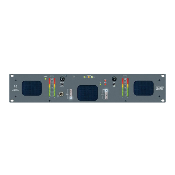
2U Digital Audio Speaker Monitor
With SDI Input and Output on BNC, Two AES Inputs on
BNC and XLR, Two AES Outputs From SDI on BNC, Four
Analog Inputs on XLR, Two Selected Analog Stereo Outputs
on XLR, Two Mechanical VU (AV) or PPM (AM) Level Meters,
Summable Channel Assignment, and Phase Indication
Title and Contents .......................................................................
Introduction .........................................................................................
Section 1: Features, Specs, and Installation ....................
Description and Features ......................................................................
Applications and Specifications ............................................................
Installation ...........................................................................................
Section 2: Operation .................................................................
Front Panel Features ............................................................................
Rear Panel Features ..............................................................................
Audio Amplifier and Speaker Configuration .........................................
Section 3: Technical Information .........................................
General Technical Observations ............................................................
SDI to AES Converter PCB (919096) ....................................................
AES to Analog Converter PCB (919050) ...............................................
AES Digital Gain Calibration Fine Adjustment (919050) ........................
AES Error Jumper Location (919050 PCB) ............................................
PPM Meter Specifications and Level Threshold Settings ........................
VU Meter Specifications and Level Threshold Adjustment......................
AMP2-VSDA/AM and
AMP2-VSDA/AV
Document P/N 821576 Rev-B
User Manual
CONTENTS
ECO-2501 (08/03/04)
1
2
3
4
5
6
7
8
12
16
17
18
19
20
21
22
23
23
24
Advertisement
Table of Contents

Related Manuals for Wohler AMP2-VSDA/AM


Summary of Contents for Wohler AMP2-VSDA/AM
-
Page 1: Table Of Contents
AES to Analog Converter PCB (919050) ..........AES Digital Gain Calibration Fine Adjustment (919050) ......AES Error Jumper Location (919050 PCB) ..........PPM Meter Specifications and Level Threshold Settings ......VU Meter Specifications and Level Threshold Adjustment...... AMP2-VSDA/AV and AMP2-VSDA/AM Interconnect Block Diagram ..ECO-2501 (08/03/04) -
Page 2: Introduction
AMP2-VSDA/AV and AMP2-VSDA/AM User Manual P/N 821576 Rev-B Introduction Congratulations on your selection of a Wohler Technologies AMP2-VSDA/AV or AMP2-VSDA/AM audio monitor unit. We are confident it represents the best performance and value available, and we guarantee your satisfaction with it. -
Page 3: General Features
AMP2-VSDA/AV and AMP2-VSDA/AM User Manual P/N 821576 Rev-B Section 1 General Features and Specifications Description Features Applications Specifications Installation © 2004 Wohler Technologies Inc. ALL rights reserved... -
Page 4: Section 1: Features, Specs, And Installation
AMP2-VSDA/AM Series Front Panel Description The AMP2-VSDA/AV and AMP2-VSDA/AM are exceptionally high quality stereo audio monitoring systems in compact, two rackspace cabinets. All AMP2 Series units contain three audiophile-quality drivers and three power amplifiers; two amplifiers (and two speakers) that reproduce midrange and high frequency information in stereo, and a third amp/driver combination (and speaker) that handles summed Low Frequency (LF) information below the 500 Hz crossover point. -
Page 5: Applications And Specifications
Section 1: Features, Specs, and Installation Applications The AMP2-VSDA/AV and AMP2-VSDA/AM are ideally suited for use in VTR bays, mobile production vehicles, teleconferencing installations, multimedia systems, satellite links and cable TV facilities, and on-air radio studios. Designed and manufactured in the U.S., both models are backed by a strong warranty and a satisfaction guaranteed return policy. -
Page 6: Installation
AMP2-VSDA/AV and AMP2-VSDA/AM User Manual P/N 821576 Rev-B Section 1: Features, Specs, and Installation Installation Mounting The unit should be mounted where convenient for operating persons, ideally at approximately ear/eye level for best high frequency response and visual observation of the level meters. Its superior magnetic shielding eliminates concerns about locating it adjacent to most types of CRT monitors, including even high-resolution color monitors. -
Page 7: Section 2: Operation
AMP2-VSDA/AV and AMP2-VSDA/AM User Manual P/N 821576 Rev-B Section 2 Operation Front Panel Features Rear Panel Features Audio Amplifier and Speaker Configuration © 2004 Wohler Technologies Inc. ALL rights reserved... - Page 8 Front Panel Features Please refer to Figure-2a on the facing page to familiarize yourself with the front panel features of the AMP2-VSDA/AV and AMP2-VSDA/AM units. The following sections describe these features and are referenced, by number, to Figure-2a. Speakers The monitor features two mid-range speakers (left and right) and one woofer speaker. Two amplifier/driver combinations handle midrange and high frequency information in the left and right (stereo) speaker channels, while the third channel reproduces and sums the left and right channel information below the 500 Hz crossover point in the woofer (bass) speaker(s).
- Page 9 AMP2-VSDA/AV and AMP2-VSDA/AM User Manual P/N 821576 Rev-B Section 2: Operation Figure-2a: Front Panel Features © 2004 Wohler Technologies Inc. ALL rights reserved...
- Page 10 AMP2-VSDA/AV and AMP2-VSDA/AM User Manual P/N 821576 Rev-B Section 2: Operation Front Panel Features (Continued) Phase Indication LEDs These three LEDs indicate the instantaneous and average phase (polarity) conditions between the two signals in the channel pair (or downmix) assigned to the left and right speaker channels. The two smaller LEDs labeled FAST show instantaneous phase relationships in the signal.
- Page 11 AMP2-VSDA/AV and AMP2-VSDA/AM User Manual P/N 821576 Rev-B Section 2: Operation Figure-2a: Front Panel Features © 2004 Wohler Technologies Inc. ALL rights reserved...
- Page 12 AMP2-VSDA/AV and AMP2-VSDA/AM User Manual P/N 821576 Rev-B Section 2: Operation Rear Panel Features Please refer to Figure-2b on the facing page to familiarize yourself with the rear panel features of the AMP2-VSDA/AV and AMP2- VSDA/AM unit. The following sections describe these features and are referenced, by letter, to Figure-2b.
- Page 13 AMP2-VSDA/AV and AMP2-VSDA/AM User Manual P/N 821576 Rev-B Section 2: Operation Figure-2b: Rear Panel Features © 2004 Wohler Technologies Inc. ALL rights reserved...
- Page 14 Section 2: Operation AMP2-VSDA/AV and AMP2-VSDA/AM User Manual P/N 821576 Rev-B Rear Panel Features (Continued) AES Input Level Gain Calibration DIP Switch Input Level Gain Calibration, the analog level which corresponds to a given digital input value, is settable via this DIP switch.
- Page 15 Section 2: Operation AMP2-VSDA/AV and AMP2-VSDA/AM User Manual P/N 821576 Rev-B Figure-2b: Rear Panel Features © 2004 Wohler Technologies Inc. ALL rights reserved...
- Page 16 AMP2-VSDA/AV and AMP2-VSDA/AM User Manual P/N 821576 Rev-B Section 2: Operation Audio Amplifier and Speaker Configuration General Description All models in the AMP Series contain high performance transducers (speakers) driven by three power amplifiers; two amplifier/ driver combinations handle midrange and high frequency information in the left and right (stereo) speaker channels, while the third amplifier channel sums the left and right channel information below the 500 Hz crossover point in the woofer (bass) speaker(s).
-
Page 17: Section 3: Technical Information
AMP2-VSDA/AV and AMP2-VSDA/AM User Manual P/N 821576 Rev-B Section 3 Technical Information General Technical Observations SDI to AES Converter Module PCB (919096) AES to Analog Converter Module PCB (919050) AES Digital Gain Fine Adjustment (919050) AES Error Jumper Locations (919050) -
Page 18: General Technical Observations
AMP2-VSDA/AV and AMP2-VSDA/AM User Manual P/N 821576 Rev-B Section 3: Technical Information General Technical Observations General Mechanical Observations Elimination of cabinet and component sympathetic vibrations (resonances) requires considerable attention to mechanical details. Because of this, and the physical constraints of the speaker’s acoustic enclosures, even minor changes to any of the mechanical details of the unit can seriously impair its acoustic performance. -
Page 19: Sdi To Aes Converter Pcb (919096)
SDI to AES Converter Module PCB (919096) The 919096 (Serial Digital to AES Converter) module allows selected Wohler Technologies audio monitoring systems to be connected directly to a serial digital video signal containing embedded audio. Two levels of component signals (eg., D1, D5, and Digi Betacam type) are currently supported;... -
Page 20: Aes To Analog Converter Pcb (919050)
AES to Analog Converter Module PCB (919050) Description The 919050 Digi-2 (Dual Input AES to Analog Converter) module allows selected Wohler Technologies products to receive input signals in the AES or SPDIF digital audio data formats. Sampling rate and format selection are sensed and set automatically. -
Page 21: Aes Digital Gain Calibration Fine Adjustment (919050)
AMP2-VSDA/AV and AMP2-VSDA/AM User Manual P/N 821576 Rev-B Section 3: Technical Information AES Digital Gain Calibration Fine Adjustment (919050) The digital gain calibration is set at the factory for +4 dB (Analog) = -20 dBFS (Digital). Three other values (+8 = -20, +6 = -9, and 0 = -18) may also be user selected via a DIP switch on the rear panel (Item H, page 14). -
Page 22: Aes Error Jumper Location (919050 Pcb)
AMP2-VSDA/AV and AMP2-VSDA/AM User Manual P/N 821576 Rev-B Section 3: Technical Information AES Error Jumper Locations (919050) To disable indication of faulty AES data (and leave only indi- cation of faulty reception), place jumpers on both H14 and H18. See Item 5, page 8 for more information. -
Page 23: Ppm Meter Specifications And Level Threshold Settings
AMP2-VSDA/AV and AMP2-VSDA/AM User Manual P/N 821576 Rev-B Section 3: Technical Information PPM Level Meter Specifications and Level Threshold Settings The two (one per meter) Level Threshold DIP switches in the AM (PPM) unit are only accessible by removal of the top cover. Each DIP switch is physically located on the inside front panel above the level meter to which it is dedicated. -
Page 24: Amp2-Vsda/Av And Amp2-Vsda/Am Interconnect Block Diagram
AMP2-VSDA/AV and AMP2-VSDA/AM User Manual P/N 821576 Rev-B Section 3: Technical Information © 2004 Wohler Technologies Inc. ALL rights reserved... - Page 25 AMP2-VSDA/AV and AMP2-VSDA/AM User Manual P/N 821576 Rev-B NOTE: PCB layout and schematic support documentation is available upon request. Wohler Technologies, Inc. 713 Grandview Drive South San Francisco, CA 94080 650 589-5676 Fax: 650 589-1355 web: www.wohler.com e-mail: support@wohler.com © 2004 Wohler Technologies Inc. ALL rights reserved...
- Page 26 AMP2-VSDA/AV and AMP2-VSDA/AM User Manual P/N 821576 Rev-B Wohler Technologies, Inc. 713 Grandview Drive South San Francisco, CA 94080 650 589-5676 Fax: 650 589-1355 web: www.wohler.com e-mail: support@wohler.com © 2004 Wohler Technologies Inc. ALL rights reserved...