Table of Contents
Advertisement
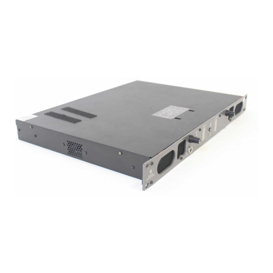
AMP1A Series
AMP1A-4S AMP1A-10S AMP1A-LP4S AMP1A-LP10S
1U Multi-Channel Audio Speaker Monitors
with Four or Ten Analog Audio Inputs,
Stereo Analog Outputs, and Optional Dual
10-Segment Level Meters and Phase Indication
Title and Contents ...........................................................
Important Safety Instructions and Introduction ..........................................
Description and Features ......................................................................
Applications, General Specifications, and Other Options ...........................
Installation ..............................................................................................
Section 2: Operation ..................................................................
Front Panel Features ...............................................................................
Rear Panel Features .................................................................................
Section 3: Technical Information .......................................
General Technical Observations ...............................................................
Level Meter Gain Calibration and Display Mode Settings .........................
Bargraph Driver Circuit Description (919017) ..........................................
Level Meter Specifications .......................................................................
Interconnect Block Diagrams ..................................................................
© 2006 Wohler Technologies Inc. ALL rights reserved
Document P/N 821527 Rev-B
User Manual
CONTENTS
1
2
3
4
5
6
7
8
10
13
14
15
16
16
17
18
1
Advertisement
Table of Contents

Related Manuals for Wohler AMP1A-4S


Summary of Contents for Wohler AMP1A-4S
-
Page 1: Table Of Contents
General Technical Observations ............... Level Meter Gain Calibration and Display Mode Settings ......Bargraph Driver Circuit Description (919017) .......... Level Meter Specifications ............... Multi-Channel Analog Switching PCB Circuit Description (919013) ..Interconnect Block Diagrams ..............© 2006 Wohler Technologies Inc. ALL rights reserved... -
Page 2: Important Safety Instructions And Introduction
Introduction Congratulations on your selection of a Wohler Technologies product. We are confident it represents the best performance and value available, and we guarantee your satisfaction with it. If you have questions or comments you may contact us at: Wohler Technologies, Inc. -
Page 3: Section 1: General Features And Specifications
AMP1A-4S/-10S/-LP4S/-LP10S User Manual P/N 821527 Rev-B Section 1 General Features and Specifications Description Features Applications General Specifications Other Options © 2006 Wohler Technologies Inc. ALL rights reserved... -
Page 4: Description And Features
The AMP1A-4S model features four pairs (8 channels) of balanced inputs on Phoenix connectors and the AMP1A-10S features ten pairs (20 channels) of these inputs. Any pair of inputs is selectable for monitoring via a rotary source select switch on the front panel. -
Page 5: Applications, General Specifications, And Other Options
Typical 1/6 Octave Audio Response Curve Other Options Wohler Technologies offers by far the broadest range of standard production audio monitor units. Standard-production models or special order custom features for the AMP1A Series (1U) units include the following functions (and combinations thereof): •... -
Page 6: Installation
The unit's AC mains connection is via a standard IEC inlet, with safety ground connected directly to the unit's chassis. The universal AC input (100-240VAC, 50/60Hz) switching power supply is a self-resetting sealed type, with automatic over-voltage and over-current shutdown. There is no user-replaceable fuse in either the primary or secondary circuit. © 2006 Wohler Technologies Inc. ALL rights reserved... -
Page 7: Section 2: Operation
AMP1A-4S/-10S/-LP4S/-LP10S User Manual P/N 821527 Rev-B Section 2 Operation Installation Front Panel Features Rear Panel Features © 2006 Wohler Technologies Inc. ALL rights reserved... -
Page 8: Front Panel Features
In general, observing the AVG LED alone is sufficient for proper phase monitoring. While it is normal for stereo signals to contain some intermittent instantaneous out-of-phase and in-phase conditions (FAST LEDs), a steady RED glow of the AVG LED indicates an out-of-phase alarm condition. © 2006 Wohler Technologies Inc. ALL rights reserved... - Page 9 AMP1A-4S/-10S/-LP4S/-LP10S User Manual P/N 821527 Rev-B Section 2: Operation Figure-2a: Front Panel Features © 2006 Wohler Technologies Inc. ALL rights reserved...
-
Page 10: Rear Panel Features
(Item 6, page 8). The output is not affected by the volume/balance controls or headphone mute. See below for XLR connector pinout information. Pin-1 Pin-2 High (+) (Shield) Pin-3 Low (-) Male XLR Pinout © 2006 Wohler Technologies Inc. ALL rights reserved... - Page 11 Section 2: Operation SEL. OUT CH A(L) SEL. OUT CH A(L) AMP1A-10S and AMP1A-4S and AMP1A-LP10S AMP1A-LP4S Rear Panel. Rear Panel. SEL. OUT CH B(R) SEL. OUT CH B(R) Figure-2b: Rear Panel Features © 2006 Wohler Technologies Inc. ALL rights reserved...
- Page 12 AMP1A-4S/-10S/-LP4S/-LP10S User Manual P/N 821527 Rev-B Section 2: Operation (This page left intentionally blank) © 2006 Wohler Technologies Inc. ALL rights reserved...
-
Page 13: Section 3: Technical Information
• Level Meter Gain Calibration and Display Mode Settings • 919017 - Level Meter Bargraph Driver Circuit Description • Level Meter Specifications • 919013 - Multi-Channel Analog Switching PCB Circuit Description • Interconnect Block Diagrams © 2006 Wohler Technologies Inc. ALL rights reserved... -
Page 14: General Technical Observations
(common) OR THE GROUNDED LEAD OF ANY TEST EQUIPMENT so as not to short out the power amps. The side speaker outputs are single-ended, so these precautions are not necessary for them. © 2006 Wohler Technologies Inc. ALL rights reserved... -
Page 15: Level Meter Gain Calibration And Display Mode Settings
The Meter Input Gain Calibration/Bargraph Display Mode DIP modules are accessible through openings in the top cover of the unit. Any adjusments to the DIP switch modules should be performed before installing the unit into an enclosed rack. © 2006 Wohler Technologies Inc. ALL rights reserved... -
Page 16: Bargraph Driver Circuit Description (919017)
Segment Brightness, (I f = 20 mA): 5.5 mcd Segment Brightness, Uniformity: <8% difference between segments Adjacent Segment "Off" Brightness: <1% of brightness of active segment Peak Emission Wavelength: green: 570 nm red: 630 nm © 2006 Wohler Technologies Inc. ALL rights reserved... -
Page 17: Multi-Channel Analog Switching Pcb Circuit Description (919013)
<.O5 % Response: +/- .5 dB 20 Hz - 20 KHz Output gain: 0 dB balanced, -10 dB unbalanced Maximum output: +16 dBv Power: Less than 30 mA with a 24 volt supply © 2006 Wohler Technologies Inc. ALL rights reserved... -
Page 18: Interconnect Block Diagrams
AMP1A-4S/-10S/-LP4S/-LP10S User Manual P/N 821527 Rev-B Section 3: Technical Information © 2006 Wohler Technologies Inc. ALL rights reserved... - Page 19 AMP1A-4S/-10S/-LP4S/-LP10S User Manual P/N 821527 Rev-B Section 3: Technical Information © 2006 Wohler Technologies Inc. ALL rights reserved...
- Page 20 Technologies, Inc. Phone: (510) 589-5676 31055 Huntwood Avenue Fax: (510) 870-0811 Hayward, CA 94544 US Toll-Free: 1-888-596-4537 web: www.wohler.com Phone: (510) 870-0810 e-mail: support@wohler.com Fax: (510) 870-0811 US Toll-Free: 1-888-596-4537 www.wohler.com support@wohler.com © 2006 Wohler Technologies Inc. ALL rights reserved...
Need help?
Do you have a question about the AMP1A-4S and is the answer not in the manual?
Questions and answers