Advertisement
Table of Contents
- 1 Customer Support
- 2 Table of Contents
- 3 Introduction
- 4 Safety Instructions
- 5 Installation Recommendations
- 6 Description
- 7 Features
- 8 Specifications
- 9 Audio Amplifier and Speaker Configuration
- 10 Front Panel Controls
- 11 Rear Panel Connectors
- 12 Line Level Calibration Instructions
- 13 Internal Switch Settings
- 14 Technical Functional Overview
- Download this manual
Advertisement
Table of Contents

Subscribe to Our Youtube Channel
Related Manuals for Wohler AMP1A-VTR2


Summary of Contents for Wohler AMP1A-VTR2
- Page 1 CONFIDENCE IS EVERYTHING.™ World Leader of In-Rack, Audio, Video, Data Monitoring, and Closed Captioning Solutions AMP V Series • AMP1A-VTR2 • AMP2-VSDA • AMP1-V2DA Digital/Analog Audio Speaker Monitors User Guide Part Number 821021, Revision A...
-
Page 2: Customer Support
Wohler Technologies, Inc. reserves the right to change or improve our products at any time and without notice. In no event will Wohler Technologies, Inc. be liable for direct, indirect, special, incidental, or consequential damages resulting from any defect in the hardware, software, or its documentation, even if advised of the possibility of such damages. -
Page 3: Table Of Contents
AMP V Series User Guide Introduction Overview The AMP V Series monitors are audio monitors capable of audibly monitoring up to four analog source channels through an internal stereo speaker system while simultaneously visually monitoring all four channels of the selected source via four high-resolution LED bar graph level meters. -
Page 4: Safety Instructions
A M P V S e r ie s U s e r G u i d e S a f e t y I n s tr u c ti o n s Safety Instructions Read, keep, and follow all of these instructions; heed all warnings. Do not use this equipment near water. -
Page 5: Installation Recommendations
AMP V Series User Guide I n s ta l la t i o n R e c o m me n d a t io n s Installation Recommendations Unpacking Unpack the AMP V Series monitor from the shipping container and inspect all components for shipping damage. -
Page 6: Description
Wohler Technologies proprietary three-LED stereo phase indication feature allows monitoring of phase relationships of the selected channels assigned to the left and right speaker channels. -
Page 7: Features
AMP V Series User Guide F e a t u r e s Features • 98 dB SPL at two feet • Excellent high frequency response for positive detection of background whine and noise • Audible and visual indication of phase/polarity problems •... -
Page 8: Specifications
A M P V S e r ie s U s e r G u i d e S p e c if i c a ti o n s Specifications Table 1–1 lists the specifications for the AMP V Series monitors. Table 1–1 AMP V Series Monitors Specifications Specifications... -
Page 9: Audio Amplifier And Speaker Configuration
AMP V Series User Guide A u d i o A m p l i f i e r a n d S p e a k e r C o n f i g u r a t i o n Audio Amplifier and Speaker Configuration Audio Amplifiers... -
Page 10: Front Panel Controls
A M P V S e r ie s U s e r G u i d e F r o n t P a n e l C o n t r o l s Front Panel Controls Common Controls •... - Page 11 AMP V Series User Guide F r o n t P a n e l C o n t r o l s before releasing it. This will preserve the current selection set as though the button was never pushed. •...
- Page 12 Group Headphones Level Meters Speaker Assign Speakers Group Select (Toggle Switch): On the AMP1A-VTR2 model, this switch selects between the two groups ( ) of four Group 1 Group 2 channels as input on the rear panel. It is from the selected group of four...
- Page 13 AMP V Series User Guide F r o n t P a n e l C o n t r o l s AMP1-V2DA-Specific Controls Figure 1–3 AMP1-V2DA Front Panel AES 1 & 2 Speaker Assign Power Volume Balance Brightness Headphones Analog/Digital Phase...
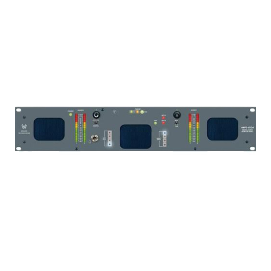
- Page 14 A M P V S e r ie s U s e r G u i d e F r o n t P a n e l C o n t r o l s AMP2-VSDA-Specific Controls Figure 1–4 AMP2-VSDA Front Panel AES 1 &...
-
Page 15: Rear Panel Connectors
AMP V Series User Guide R e a r P a n e l C o n n e c t o r s signal present the LED will be unlit. This LED functions whether or not the SDI digital signal is selected for monitoring through the unit. Rear Panel Connectors Common Connectors Descriptions •... - Page 16 GROUP 2 GROUP 1 GROUP 2 VU/VU Technologies OPERATE +1-510-870-0810 CALIBRATE VU/PPM +1-510-870-0811 www.Wohler.com SERIAL NO. AMP1A-VTR2 PPM/PPM MONTH 253836 1 2 3 4 5 6 INPUTS YEAR MADE IN U.S.A. Line Level Calibration Power Analog Inputs (2 Banks 4) •...
- Page 17 AMP V Series User Guide R e a r P a n e l C o n n e c t o r s • AES Termination (Four-Position DIP Switch): This DIP switch sets the termination for the AES inputs. If an AES input channel is fed to downstream equipment, the associated DIP switch must be in the up position (unterminated).
- Page 18 A M P V S e r ie s U s e r G u i d e R e a r P a n e l C o n n e ct o r s • Converted Analog Out (Converted from AES Inputs) (Phoenix, 3- Pin Male, Outputs 1 through 4): These connectors output standard, balanced analog signals converted from the AES digital inputs (but not the analog inputs) and are not affected by the position of the...
-
Page 19: Line Level Calibration Instructions
AMP V Series User Guide L i n e L e v e l C a li b r at i o n In s t r u c t io n s • AES Out from SDI (1 and 2, on BNC): These two unbalanced (75 ) loop-through connectors each output a copy of the de-embedded audio from the SDI input. - Page 20 A M P V S e r ie s U s e r G u i d e L in e L e v e l C a l ib ra t i o n I n s tr u c ti o n s Note: Position 6 of the DIP Switch is not used.
- Page 21 AMP V Series User Guide L i n e L e v e l C a li b r at i o n In s t r u c t io n s Place DIP section 1 in the up position and return unit to service. Only one auto-calibration attempt may be made for each cycling of AC power to the unit.
-
Page 22: Internal Switch Settings
Figure 1–15 on page 22 for alternate scales. Contact Wohler Technologies for more information about Alternate Scale labels. © 2 01 0 Wo h le r Te ch n ol og ie s , I n c . A l l r i g h t s r e s e rve d . - Page 23 AMP V Series User Guide I n te rn al S wi t ch S e t t in g s Figure 1–13 Internal DIP Switch Location (PCB 919174) © 2 01 0 Wo h le r Te ch n o l og ie s, I n c . A l l r i g h t s r e s e r v e d .
- Page 24 A M P V S e r ie s U s e r G u i d e In te r n a l Sw i tc h S e t ti n g s Figure 1–14 AMP2-VSDA Alternative Scales Figure 1–15 AMP1-VSDA and AMP1-VTR2 Alternative Scales...
- Page 25 (a special option specified at time of order) or by removing power and then reapplying power to the unit (unplug/ replug power cord). Contact Wohler Technologies for more information about this feature. PPM Characteristics The PPM characteristics determine the integration time (rise time) and return time (fall time) of the level meter.
-
Page 26: Technical Functional Overview
A M P V S e r ie s U s e r G u i d e T e c h n i c a l F u n c t i o n a l O v e r v i e w at the time of order or requested from Wohler for application to existing units. - Page 27 AMP V Series User Guide T e c h n i c al F u n c ti o n al O v e r v ie w Figure 1–17 AMP1- V2DA Block Diagram 26-Segment 2 3 4 High-Resolution Analog Headphone Inputs Level Meters...
- Page 28 AMP V Series User Guide T e c h n i c a l F u n c t i o n a l O v e r v i e w Figure 1–18 AMP2-VSDA Block Diagram 53-Segment High-Resolution Analog Level Meters Inputs Headphone...
- Page 29 AMP V Series User Guide T e c h n i c al F u n c ti o n al O v e r v ie w Figure 1–19 AMP2-VTR2 Block Diagram 26-Segment High-Resolution Level Meters Headphone Group 1 Group Group 2 Left...
- Page 30 A M P V S e r ie s U s e r G u i d e T e c h n i c a l F u n c t i o n a l O v e r v i e w ©...
Need help?
Do you have a question about the AMP1A-VTR2 and is the answer not in the manual?
Questions and answers