
Related Manuals for Advantech SIMB-M21


Summary of Contents for Advantech SIMB-M21
- Page 1 User Manual SIMB-M21 Intel® HM65 with Core™ i7/ i5/ i3/ Celeron Mini-ITX Motherboard...
-
Page 2: Safety Information
The symbol of the crossed out wheeled bin indicates that the product (electri- cal and electronic equipment) should not be placed in municipal waste. Check local regulations for disposal of electronic products. Part No. 20060M2100 Edition 1 Printed in China September 2011 SIMB-M21 User Manual... -
Page 3: Conventions Used In This Guide
Refer to the following sources for additional information and for product and software updates. Advanetch websites The Advantech website provides updated information on Advantech hardware and software products. Refer to the Advantech contact information. www.advan- tech.com.tw Optional documentation Your product package may include optional documentation, such as warranty flyers, that may have been added by your dealer. -
Page 4: Packing List
/iP5P800VM.ROM Packing List Before you begin installing your single board, please make sure that the following materials have been shipped: 1 x SIMB-M21 Mini ITX main board 1 x CD ROM per carton, which contains the followings: –... -
Page 5: Table Of Contents
LVDS Back Light controller form SIO (JBLK1)......23 2.7.4 LVDS Back light power selection ..........24 2.7.5 AT/ATX Power Mode Select (PSON1)........24 Connectors....................25 2.8.1 Rear panel connectors..............25 Table 2.6: LAN port LED indications ......... 25 SIMB-M21 User Manual... - Page 6 3.4.13 Intel ICC..................61 3.4.14 Sandybridge DTS Configuration ..........62 3.4.15 Sandybridge PPM Configuration ..........62 Chipset....................63 3.5.1 System Agent (SA) Configuration..........64 3.5.2 PCH-IO Configuration..............71 Boot......................75 Security ....................76 Save & Exit ..................... 77 SIMB-M21 User Manual...
-
Page 7: Chapter 1 Product Overview
Chapter Product Overview... -
Page 8: Specifications Summary
LAN1: Intel 82579LM LAN2: Intel 82583V 1.1.6 I/O Port Back Panel: 1 x VGA Port, 1 x HDMI Port, 1 x DisplayPort, 1 x COM RS-232 Port 4 x USB 2.0/1.1 Ports, SIMB-M21 User Manual... -
Page 9: Mechanical & Environmental
Operating Temperature 0° C to 50° C (32° F to 122° F) Operating Humidity 0% to 90% relative humidity, non-condensing Size (L x W) 6.69" x 6.69" (170 x 170mm) Weight 1.03 lbs (0.47 Kg) * Specifications are subject to change without notice. SIMB-M21 User Manual... -
Page 10: Block Diagram
Block Diagram Figure 1.1 Block Diagram SIMB-M21 User Manual... -
Page 11: Chapter 2 Product Introduction
Chapter Product Introduction... -
Page 12: Product Highlights
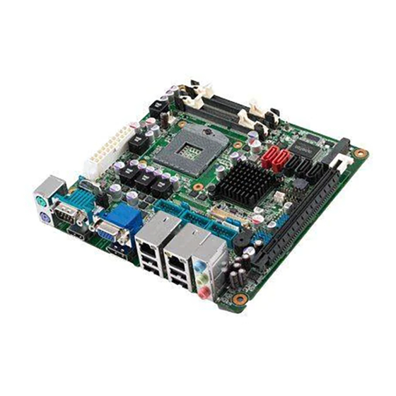
Product highlights 2.1.1 Product Overview SIMB-M21 supports the latest Intel rPGA998 CPU-socket interface processor, the 2nd Generation Intel® Core i3, i5, i7, Celeron mobile processors which are built on 32 nm technologies to provide smart performance and responsiveness. SIMB-M21 has 2 SATAIII and 2 SATAII connects, and also has integrated 5.1-channel HD Audio and dual Gigabit LAN. -
Page 13: Before You Proceed
Before you install or remove any component, ensure that the ATX power supply is switched off or the power cord is detached from the power supply. Failure to do so may cause severe damage to the motherboard, peripherals, and/or components. SIMB-M21 User Manual... -
Page 14: Motherboard Overview
Placement Direction When installing the motherboard, make sure that you place it into the chassis in the correct orientation. The edge with external ports goes to the rear part of the chassis as indicated in the image below. SIMB-M21 User Manual... -
Page 15: Screw Holes
Attach the four (4) screws into the holes indicated by the red circles to secure the motherboard to the chassis. Caution! Do not over tighten the screws! Doing so can damage the motherboard. Place this side towards the rear of the chassis. SIMB-M21 User Manual... -
Page 16: Motherboard Layout
3 x 1 header, pitch 2.54mm PSON1 AT/ATX Mode Select 3 x 1 header, pitch 2.54mm JBLK1 BL controller from SIO 3 x 1 header, pitch 2.54mm JCOMPWR3 COM3 COM4 COM5 JCOMPWR4 2 x 3 header, pitch 2.0 mm RI/+5V/+12V Select JCOMPWR5 SIMB-M21 User Manual... -
Page 17: Table 2.3: Rear Panel Connector
LCD Inverter Connector 1 x 5 connector SPI Connector 4 x 2 header, pitch 2.54mm SATA1 ~ 5 SATA Data Connector * 5 7P Male connector USB45 USB89 USB Connector * 6 5 x 2 header, pitch 2.54mm USB1011 SIMB-M21 User Manual... -
Page 18: Central Processing Unit (Cpu)
Contact your retailer immediately if the PnP cap is missing, or if you see any damage to the PnP cap/socket pins/motherboard components. Advantech will shoulder the cost of repair only if the damage is shipment/transit-related. ... - Page 19 Caution! Before installing the CPU, make sure that the socket box is facing towards you and the load lever is on your left. Separate CPU cooler and its base first by screw drawer Assemble the CPI FAN retention module SIMB-M21 User Manual...
- Page 20 Turn the CPU lock clockwise to lock CUU Caution! The CPU fits in only one correct orientation. DO NOT force the CPU into the socket to prevent bending the connectors on the socket and damag- ing the CPU! SIMB-M21 User Manual...
-
Page 21: Installing The Cpu Heatsink And Fan
Place the heatsink base on the relative bottom of motherboard. Place the heatsink assembly on the top of the CPU, making sure that the four fasteners match the holes on the motherboard. Screw tightly the four fasteners. SIMB-M21 User Manual... -
Page 22: System Memory
A DDR3 module has the same physical dimensions as a DDR SO-DIMM but has a 204-pin footprint compared to the 204-pin DDR2 DIMM. DDR3 DIMMs are notched differently to prevent installation on a DDR2 DIMM socket. The following figure illus- trates the location of the sockets: SIMB-M21 User Manual... -
Page 23: Table 2.5: 204-Pin Ddr3 Dimm Sockets
Due to CPU limitation, DIMM modules with 128 Mb memory chips or double-sided x16 memory chips are not supported in this moth- erboard. 2.5.3 Installing a SO-DIMM Unlock a DIMM socket by pressing the retaining clips outward. SIMB-M21 User Manual... - Page 24 A DDR3 SO-DIMM is keyed with a notch so that it fits in only one direction. DO NOT force a SO-DIMM into a socket to avoid damag- ing the SO-DIMM. The DDR3 SO-DIMM sockets do not support DDR SO-DIMMs. DO NOT install DDR2 SO-DIMMs to the DDR3 SO-DIMM socket. SIMB-M21 User Manual...
-
Page 25: Removing A So-Dimm
Warning! Make sure to unplug the power cord before adding or removing expan- sion cards. Failure to do so may cause you physical injury and damage motherboard components. SIMB-M21 User Manual... -
Page 26: Installing An Expansion Card
Assign an IRQ to the card if needed. Refer to the tables on the next page. Install the software drivers for the expansion card. 2.6.3 PCI Express x16 slot This motherboard supports one PCI Express x16. The following figure shows a graphics card installed on the PCI Express x16 slot. SIMB-M21 User Manual... -
Page 27: Mini Pci Express
Decode card installed on the MINI PCI Express slot. 2.6.5 CFast Card This motherboard supports one CFast Card connector and its location is on button side of MB. The following figure shows a CFast Card installed on the CFast Card connector. SIMB-M21 User Manual... -
Page 28: Jumpers
You do not need to clear the RTC when the system hangs due to over- clocking. For system failure due to overclocking, use the C.P.R. (CPU Parameter Recall) feature. Shut down and reboot the system so the BIOS can automatically reset parameter settings to default values. SIMB-M21 User Manual... -
Page 29: Com3, Com4, Com5 Ri/+5V/+12V Select (Jcompwr3 Jcompwr4 Jcompwr5)
2.7.2 COM3, COM4, COM5 RI/+5V/+12V Select (JCOMPWR3 JCOMPWR4 JCOMPWR5) This jumper allows you to select the power mode of COM PORTATX Mode or AT mode. +12V 2.7.3 LVDS Back Light controller form SIO (JBLK1) Linear SIMB-M21 User Manual... -
Page 30: Lvds Back Light Power Selection
2.7.4 LVDS Back light power selection +5 V +3.3 V 2.7.5 AT/ATX Power Mode Select (PSON1) This jumper allows you to select ATX Mode or AT mode. ATX MODE (Default) AT MODE SIMB-M21 User Manual... -
Page 31: Connectors
10. Line Out port (lime). This port connects a headphone or a speaker. In 4-channel, 6-channel, and 8-channel configuration, the function of this port becomes Front Speaker Out. 11. Microphone port (pink). This port connects a microphone. SIMB-M21 User Manual... -
Page 32: Cpu And System Fan Connectors (Cpu_Fan1, Sys_Fan1)
Caution! Do not forget to connect the fan cables to the fan connectors. Insuffi- cient air flow inside the system may damage the motherboard compo- nents. These are not jumpers! DO NOT place jumper caps on the fan connec- tors. SIMB-M21 User Manual... -
Page 33: System Panel (F_Panel)
Hard Disk Drive Activity LED (Pin 1-3 HDLED) This 2-pin connector is for the HDD Activity LED. Connect the HDD Activity LED cable to this connector. The IDE LED lights up or flashes when data is read from or written to the HDD. SIMB-M21 User Manual... -
Page 34: Atx Power Connectors (Eatxpwr1, Atx12V1)
Make sure that your power supply unit (PSU) can provide at least the minimum power required by your system. See the table below for details. SIMB-M21 User Manual... -
Page 35: Serial Port Connectors (Com3, Com4, Com5)
This connector is for a serial (COM) port. Connect the serial port module cable to this connector, then install the module to a slot opening at the back of the system chassis. COM3, COM4, COM5 2.8.6 GPIO Connector (JGPIO) This connector is for GPIO function. JDIO1 SIMB-M21 User Manual... -
Page 36: Audio Mic.-In & Line-Out Connector (Fpaud1)
Important! For motherboards with the optional HD Audio feature, we recommend that you connect a high-definition front panel audio module to this con- nector to avail of the motherboard's high-definition audio capability. 2.8.8 LVDS Connector (LVDS1) The connector is for 24-bit dual channel LVDS panel. LVDS1 SIMB-M21 User Manual... -
Page 37: Lcd Inverter Connector (Jbl1)
Signal Signal Description For inverter with adjustable Backlight function, it is possible to con- trol the LCD brightness through the VR signal. Vadj=0.75V ~ 4.25V (Recommended: 4.7K Ω , > 1/16W) ENBKL LCD backlight ON/OFF control signal SIMB-M21 User Manual... -
Page 38: Spi Connector (Jspi)
OC-192 (10 Gb/s) and beyond, enabling them to dramatically increase system performance. JSPI 2.8.11 LPC Connector (JLPC1) SATA1, SATA2 SIMB-M21 User Manual... -
Page 39: Serial Ata 3 Connector (Sata1, Sata2)
These connectors support SATA 3.0 and are for the Serial ATA signal cables for Serial ATA hard disk drives. SATA1, SATA2 2.8.13 Serial ATA II Connector (SATA3, SATA4, SATA5) These connectors support SATA 2.0 and are for the Serial ATA signal cables for Serial ATA hard disk drives. SATA1, SATA2 SIMB-M21 User Manual... -
Page 40: Case Open Connectors (Jcase1)
Connect the right-angle side of SATA signal cable to SATA device. Or you may connect the right-angle side of SATA cable to the onboard SATA port to avoid mechanical conflict with large graphics cards. 2.8.14 Case open connectors (JCASE1) JCASE12 SIMB-M21 User Manual... -
Page 41: Usb Connectors (Usb45, Usb89, Usb1011)
These USB connectors comply with USB 2.0 specification that sup- ports up to 480 Mbps connection speed. USB56, USB78, USB910, USB1112 Caution! Never connect a 1394 cable to the USB connectors. Doing so will dam- age the motherboard! Note! The USB module is purchased separately. SIMB-M21 User Manual... - Page 42 SIMB-M21 User Manual...
-
Page 43: Bios Setup
Chapter BIOS Setup This chapter tells how to change the system setting through the BIOS setup menus. Detailed descriptions of the BIOS parame- ters are also provided. -
Page 44: Bios Setup Program
Change Option / Field/ Value Enter Go to Sub Screen PGDN Next Page PGUP Previous Page HOME Go to Top of Screen Go to Bottom of Screen General Help Previous Value Optimized Default Save & Exit Setup Exit SIMB-M21 User Manual... -
Page 45: List Box
To access the menu items, press the up/down/right/left arrow key on the keyboard until the desired item is highlighted, then press [Enter] to open the specific menu. SIMB-M21 User Manual... -
Page 46: Main Setup
BIOS Information Display the auto-detected BIOS information. Memory Information Displays the auto-detected system memory System Date The date format is <Date>,<Month>,<Day>,<Year>. System Time The time format is <Hour>,<Minute>,<Second>. Access Level Displays the accessory information. SIMB-M21 User Manual... -
Page 47: Advanced Bios Setup
The Advanced BIOS Setup screen is shown below. The sub menus are described on the following pages. Caution! Take caution when changing the settings of the Advanced menu items. Incorrect field values can cause the system to malfunction. SIMB-M21 User Manual... -
Page 48: Pci Subsystem Setting
Enables or disables VGA palette registers snooping. Configuration options: [Disabled] [Enabled].\ PERR# Generation [Disable] Enables or disables PCI devices to Generate PERR#. Configuration options: [Disabled] [Enabled]. SPERR# Generation [Disable] Enables or disables PCI devices to Generate SPERR#. Configuration options: [Disabled] [Enabled]. SIMB-M21 User Manual... - Page 49 Set the ASPM levels: Force L0 - Force all links to L0 state; AUTO - BIOS config- uration; Disable - Disable ASPM. Configuration options: [Disable][Auto][Force L0]. Caution! Enabling ASPM may cause some PCI Express devices to fail. Extended Sync [Disables] If [Enabled] allows generation of extended synchronization patterns. Configuration options: [Disable][Enabled]. SIMB-M21 User Manual...
-
Page 50: Acpi Settings
Configuration options: [Suspend Disable][S1 (CPU Stop Clock)] [S3 (suspend to RAM )] Resume On RTC Alarm [Disable] Enable or disable system wake on alarm even. When enabled, system will wake upon the hr/min/sec specified. Configuration options: [Disabled] [Enabled]. SIMB-M21 User Manual... -
Page 51: Trusted Computing
3.4.3 Trusted computing Trusted computing (TPM) settings. TPM configuration TPM SUPPORT [Disabled] Enable or disable TPM support. Configuration options: [Disabled] [Enabled]. Current TPM Status Information Displays the TPM status information [No TPM Hardware]. SIMB-M21 User Manual... -
Page 52: Cpu Configuration
Configuration options: [Disabled] [Enabled]. Hardware Prefetcher [Enable] To turn on/off the Mid Level Cache (L2) streamer Prefetcher. Configuration options: [Disabled] [Enabled]. Adjacent Cache Line Prefetcher [Enable] To turn on/off prefetching of adjacent cache lines. Configuration options: [Disabled] [Enabled]. SIMB-M21 User Manual... -
Page 53: Sata Configuration
SATA Mode [IDE Mode] Supports IDE, AHCI. Configuration options: [Disable][IDE Mode][AHCI Mode]. Serial-ATA Controller 0 [Compatible] Enabled/Disabled Serial-ATA Controller 0. Configuration options: [Disable] [Enhanced] [Compatible]. Serial-ATA Controller 1 [Enhanced] Enabled/Disabled Serial-ATA Controller 1. Configuration options: [Disable] [Enhanced] [Compatible]. SIMB-M21 User Manual... -
Page 54: Intel Txt(Lt) Configuration
3.4.6 Intel TXT(LT) Configuration Display Intel Trusted Execution Technology configuration. 3.4.7 PCH-FW Configuration Configuration Management Engine Technology Parameter. Display ME Firmware Information SIMB-M21 User Manual... - Page 55 3.4.7.1 Firmware Update Configuration Me FW Image Re-Flash[Disable] Enabled/Disabled Me FW Image Re-Flash function. Configuration options: [Disable] [Enhanced]. SIMB-M21 User Manual...
-
Page 56: Intel Anti-Theft Technology Configuration
Configuration options: [Disable] [Enhanced]. Intel Anti-Theft Technology Recovery[3] Set the number of times recovery attempted will be allowed. Enter Intel AT Suspend Mode[Disable] Request that platform enter Intel AT support Mode. Configuration options: [Disable] [Enhanced]. SIMB-M21 User Manual... -
Page 57: Usb Configuration
Maximum time the device will take before it properly reports itself to the Host Controller. ‘Auto’ uses default value: for a Root port it is 100ms, for a Hub port the delay is taken form Hub descriptor. Configuration options: [Auto][Manual]. SIMB-M21 User Manual... -
Page 58: Super Io Configuration
3.4.10 Super IO Configuration System Super IO Chip Parameters. Super IO Configuration Super IO Chip [NCT6776F] 3.4.10.1 Serial Port 0 configuration Set Parameters of Serial Port 0 (COMA). SIMB-M21 User Manual... - Page 59 10, 11, 12] [IO=2F8h; IRQ=3, 4, 5, 6, 7, 9. 10, 11, 12] [IO=3E8h; IRQ=3, 4, 5, 6, 7, 9. 10, 11, 12] [IO=2E8h; IRQ=3, 4, 5, 6, 7, 9. 10, 11, 12] . Super IO Chip [Finteck F81216] SIMB-M21 User Manual...
- Page 60 Select an optimal setting for Super IO device. Configuration options: [Auto] [IO=C80h; IRQ=5] [IO=C80h; IRQ=5, 7, 9. 10, 11] [IO=C88h; IRQ=5, 7, 9. 10, 11] [IO=C90h; IRQ=5, 7, 9. 10, 11] [IO=C98h; IRQ=5, 7, 9. 10, 11]. SIMB-M21 User Manual...
- Page 61 Select an optimal setting for Super IO device. Configuration options: [Auto] [IO=C88h; IRQ=5] [IO=C80h; IRQ=5, 7, 9. 10, 11] [IO=C88h; IRQ=5, 7, 9. 10, 11] [IO=C90h; IRQ=5, 7, 9. 10, 11] [IO=C98h; IRQ=5, 7, 9. 10, 11]. SIMB-M21 User Manual...
- Page 62 Select an optimal setting for Super IO device. Configuration options: [Auto] [IO=C90h; IRQ=5] [IO=C80h; IRQ=5, 7, 9. 10, 11] [IO=C88h; IRQ=5, 7, 9. 10, 11] [IO=C90h; IRQ=5, 7, 9. 10, 11] [IO=C98h; IRQ=5, 7, 9. 10, 11]. SIMB-M21 User Manual...
- Page 63 Enable or Disable Resume on PS2 MS Function. Configuration options: [Disabled] [Enabled]. Resume on Ring [Disabled] Enable or Disable Resume on Ring Function. Configuration options: [Disabled] [Enabled]. Watch Dog Timer [Disabled] Enable or Disable Watch Dog Timer Function. Configuration options: [Disabled] [Enabled]. SIMB-M21 User Manual...
- Page 64 Configure Digital I/O Pin. Configuration options: [Input][Output High][Output Low]. Digital I/O Pin 6 [Input] Configure Digital I/O Pin. Configuration options: [Input][Output High][Output Low]. Digital I/O Pin 7 [Input] Configure Digital I/O Pin. Configuration options: [Input][Output High][Output Low]. SIMB-M21 User Manual...
-
Page 65: Hardware Monitor
F] [70 C/158 F] [75 C/167 F]. ACPI Shutdown Temperature [Disable] Enabled or Disabled CPU warning temperature Function. Configuration options: [Disable] [70 C/158 F] [75 C/167 F] [80 C/176 F] [85 C/ 185] [90 C/194 F] [95 C/205 F]. SIMB-M21 User Manual... -
Page 66: Serial Port Console Redirection
Terminal Type [VT-UTF8] VT-UTF8 is the preferred terminal type for out-of-band management. The next best choice is VT100+ and then VT100. See above, in Console Redirection Set- ting page, for more help with Terminal Type/Emulation. Configuration options: [VT100][VT100+][VT-UTF8][ANSI]. SIMB-M21 User Manual... -
Page 67: Intel Icc
Enable or Disable clocks for empty PCI/PCIe slots to save power. Configuration options: [Disabled] [Enabled]. Lock ICC registers[Static only] All registers : ICC registers will be locked. Static only : only static ICC registers will be locked. Configuration options: [All registers] [Static only]. SIMB-M21 User Manual... -
Page 68: Sandybridge Dts Configuration
3.4.14 Sandybridge DTS Configuration CPU DTS[Enable] Enable or Disable CPU DTS. Configuration options: [Disabled] [Enabled]. 3.4.15 Sandybridge PPM Configuration EIST [Enable] Enable or Disable Intel Speedstep. Configuration options: [Disabled] [Enabled]. SIMB-M21 User Manual... -
Page 69: Chipset
Time window which long duration power is maintained. Short Duration power limit[0] Short duration power limit in watts, 0 means use factory default. TCC active offset[0] Offset from the factory TCC activation temperature. Chipset SIMB-M21 User Manual... -
Page 70: System Agent (Sa) Configuration
Enable or Disable SA CHAP Device. Configuration options: [Disabled] [Enabled]. Thermal Device ( B0:D4:F0) [Disable] Enable or Disable SA Thermal Device. Configuration options: [Disabled] [Enabled]. Enable NB CRID [Disable] Enable or Disable NB CRID workaround. Configuration options: [Disabled] [Enabled]. SIMB-M21 User Manual... - Page 71 [256M] [288M] [320M] [352M] [384M] [416M] [448M] [480M] [512M]. DVMT Total GFX Mem[MAX] Select DVMT5.0 total graphic memory size. Configuration options: [128MB][256MB] [MAX]. Gfx Low Power Mode[Disable] This option is applicable for SFF only. Configuration options: [Disabled] [Enabled]. SIMB-M21 User Manual...
- Page 72 Configuration options: [Auto] [Disabled] [Level 1] [Level 2] [Level 3] [Level 4] [Level 5]. Spread Spectrum clock Chip[Off] Hardware: Spectrum is controlled by Chip. Software: Spectrum is controlled by BIOS. Configuration options: [Off] [Hardware] [Software]. ALS Support[Enable] Valid only for ACPI. Configuration options: [Disabled] [Enabled]. SIMB-M21 User Manual...
- Page 73 DMI link. Configuration options: [Disabled] [L0s] [L1] [L0sL1]. DMI Extended synch Contorl[Disable] Enable or disable Extended synchronization. Configuration options: [Disabled] [Enabled]. DMI Gen2 [Enable] Set DMI Gen2 Enable or Disable. Configuration options: [Disabled] [Enabled]. SIMB-M21 User Manual...
- Page 74 ASPM L0s[Both Boot and Endpoint Ports] Enable PCIe ASPM L0s. Configuration options: [Boot Port only] [Endpoint Port only] [Both Boot and End- point Ports]. De-emphasis Control[-3.5 dB] Configure the De-emphasis control on PEG. Configuration options: [-6 dB] [-3.5 dB]. SIMB-M21 User Manual...
- Page 75 Enable or Disable RMT Crosser Support. Configuration options: [Disabled] [Enabled]. MRC Fast Boot[Ensable] Enable or Disable MRC fast boot. Configuration options: [Disabled] [Enabled]. DIMM Exit Mode[Auto] DIMM Exit Mode control. Configuration options: [Auto] [Slow Exit] [Fast Exit]. SIMB-M21 User Manual...
- Page 76 PCI Express Port Enable/Disable PCI Express Port. Configuration options: [Disabled] [Enabled][Auto]. PEG Force Gen1 PCI Express Port PEG Force Gen1. Configuration options: [Disabled] [Enabled][Auto]. Detect Non-Compliance Detect Non-Compliance PCI Express device in PEG. Configuration options: [Disabled] [Enabled][Auto]. SIMB-M21 User Manual...
-
Page 77: Pch-Io Configuration
Azalia HD Audio [Enable] Enable/Disable Azalia HD Audio. Configuration options: [Disabled] [Enabled]. Azalia internal HDMI codec [Enable] Enable/Disable Azalia internal HDMI codec. Configuration options: [Disabled] [Enabled]. SMI Lock[Disable] Enable or Disable SMI lockdown. Configuration options: [Disabled] [Enabled]. SIMB-M21 User Manual... - Page 78 High Precision Timer [Enable] Enable/Disable the High Precision Timer. Configuration options: [Disabled] [Enabled]. 3.5.2.1 USB Configuration EHCI1 [Enabled] Enable/Disable USB 2.0(EHCI) support. Configuration options: [Disabled] [Enabled]. EHCI2 [Enabled] Enable/Disable USB 2.0(EHCI) support. Configuration options: [Disabled] [Enabled]. SIMB-M21 User Manual...
- Page 79 Enable or disable the control of active state power management on SA side of the DMI link. Configuration options: [Disabled] [L0s] [L1] [L0sL1]. DMI Extended synch Contorl [Disable] Enable or disable Extended synchronization. Configuration options: [Disabled] [Enabled]. SIMB-M21 User Manual...
- Page 80 Enable or Disable to cintrol PCI Express Root Port. Configuration options: [Disabled] [Enabled][Auto]. ASPM Support[Auto] URR[Disable] FER[Disable] NFER[Disable] CER[Disable] CTO[Disable] SEFE[Disable] SENFE[Disable] SECE[Disable] PME SCI[Disable] Hot Plug[Disable] Exrea Bus Reserved[0] Reserved Memory[0] Reserved I/O[4] SIMB-M21 User Manual...
-
Page 81: Boot
Configuration options: [Force BIOS] [Keep Current]. Interrupt 19 Capture [Disable] Enabled : Allow option ROMs to trap Int19. Configuration options: [Disabled][Enabled]. Boot option priorities [Built-in EFI Shell] Select the system boot order. Configuration options: [Built-in EFI Shell][Disabled]. SIMB-M21 User Manual... -
Page 82: Security
Security Administrator Password Set setup Administrator Password. User Password Set User Password. SIMB-M21 User Manual... -
Page 83: Save & Exit
Restore Defaults Restore/Load default values for all the setup option. Save as User Defaults Save the changes done so far as User Defaults. Restore User Defaults Restore the user defaults to all the setup options. SIMB-M21 User Manual... - Page 84 No part of this publication may be reproduced in any form or by any means, electronic, photocopying, recording or otherwise, without prior written permis- sion of the publisher. All brand and product names are trademarks or registered trademarks of their respective companies. © Advantech Co., Ltd. 2011...
Need help?
Do you have a question about the SIMB-M21 and is the answer not in the manual?
Questions and answers