Table of Contents
Advertisement
Manual
ADVANTECH
SIMB-354
SAP P/N: PC-60-660
The information contained in this document has been carefully researched and is, to the best of our
knowledge, accurate. However, we assume no liability for any product failures or damages, immediate or
consequential, resulting from the use of the information provided herein. Our products are not intended for
use in systems in which failures of product could result in personal injury. All trademarks mentioned herein
are property of their respective owners. All specifications are subject to change without notice.
Advertisement
Table of Contents

Related Manuals for Advantech SIMB-354


Summary of Contents for Advantech SIMB-354
- Page 1 Manual ADVANTECH SIMB-354 SAP P/N: PC-60-660 The information contained in this document has been carefully researched and is, to the best of our knowledge, accurate. However, we assume no liability for any product failures or damages, immediate or consequential, resulting from the use of the information provided herein. Our products are not intended for use in systems in which failures of product could result in personal injury.
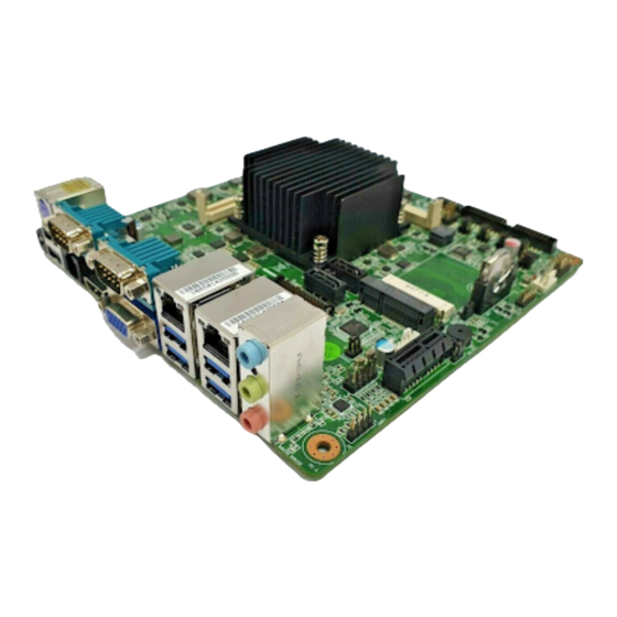
- Page 2 User Manual SIMB-354 Intel® Celeron Quad Core N3160 Mini-ITX with VGA/LVDS/HDMI/, 6 COM, Dual LAN, 10 USB, 2 Mini card, and PCIe x1...
- Page 3 The documentation and the software included with this product are copyrighted 2014 by Advantech Co., Ltd. All rights are reserved. Advantech Co., Ltd. reserves the right to improve the products described in this manual at any time without notice. No part of this manual may be reproduced, copied, translated or transmitted in any form or by any means without prior written permission from Advantech Co., Ltd.
- Page 4 Our dealers are well trained and ready to provide the sup- port required for you to experience the most from your Advantech products. Most of the problems reported are minor and can be easily solved over the phone.
-
Page 5: Declaration Of Conformity
Caution! There is a risk of a new battery exploding if incorrectly installed. Do not attempt to recharge, force open, or heat the battery. Replace the battery only with the same or equivalent type recommended by the manufac- turer. Discard used batteries according to the manufacturer's instruc- tions. SIMB-354 User Manual... - Page 6 Memory Compatibility SIMB-354 Memory Compatibility List Category Speed Capacity Vendor Chip_PN ADVANTECH P/N Result Remark DDR3L 1600MHz 4GB Advantech SEC 407 XYK0 K4B4G0846B AQD-SD3L4GN16-SG D DIE NEW Pass ME-A01528 DDR3L 1600MHz 8GB ADATA 3KE77 D9QBJ Pass ME-A02212 DDR3L 1600MHz 4GB...
-
Page 7: Product Warranty (2 Years)
Because of Advantech’s high quality-control standards and rigorous testing, most customers never need to use our repair service. If an Advantech product is defective, it will be repaired or replaced at no charge during the warranty period. For out-of-war- ranty repairs, users will be billed according to the cost of replacement materials, ser- vice time, and freight. -
Page 8: Initial Inspection
All SIMB-354 devices are mechanically and electrically inspected before shipment. Thus, your product should be free of marks and scratches and in perfect working order upon receipt. While unpacking SIMB-354, check the product for signs of shipping damage (for example, a damaged box, scratches, dents, etc.). - Page 9 SIMB-354 User Manual viii...
- Page 10 Chapter General Information...
-
Page 11: Os And Bios Compatibility
N3160 quad-core 2.24/1.6 GHz CPU with DDR3L 1333/1600MHz of up to 8 GB. The SIMB-354 offers rich I/O connectivity with four USB 3.0 and six USB 2.0 ports, as well as six COM ports integrated in a standard 170 x 170 mm form factor. The sys- tem also supports triple display for LVDS, HDMI and VGA. -
Page 12: Specifications
RAM: Up to 8 GB in two-slot 204-pin SODIMM sockets. Supports dual-channel DDR3L (low voltage) SODIMM 1.35 V modules of up to 1600 MHz SIMB-354 supports 1.35 V memory only. Users must install the memory Note! modules on the DIMMA 1 socket first. -
Page 13: Mechanical And Environmental Specifications
Jumpers and Connectors The SIMB-354 motherboard is equipped with connectors for linking the board to external devices such as hard disk drives and a keyboard. The board also features several jumpers for configuring the system according to specific applications. - Page 14 SATA power connector SATAPW2 Dual-port USB2.0 pin header F_USB78 COM4 RI# selector JCOMPWR4 COM5 RI# selector JCOMPWR5 COM6 RI# selector JCOMPWR6 Power switch/HDD LED/Power LED/System F_PANEL1 reset pin header DDR3L SODIMM socket SODIMM_A1 DDR3L SODIMM socket SODIMM_B1 SIMB-354 User Manual...
-
Page 15: Board Layout: Jumper And Connector Locations
Board Layout: Jumper and Connector Locations Figure 1.1 Jumper and Connector Locations Figure 1.2 I/O Connectors SIMB-354 User Manual... - Page 16 USB 2.0 Audio 4 x USB 3.0 USB 3.0 2 x SATA 3.0 SATA 3.0 BIOS Super I/O NCT6776F F8768E 8-bit GPIO 2 RS-232 4 RS-232 (3 x RS-232, 1 x RS-232/422/485) Figure 1.3 SIMB-354 Board Diagram SIMB-354 User Manual...
-
Page 17: Safety Precautions
Caution! There is a danger of a new battery exploding if incorrectly installed. Do not attempt to recharge, force open, or heat the battery. Replace the battery only with the same or equivalent type recommended by the man- ufacturer. Discard used batteries according to the manufacturer’s instructions. SIMB-354 User Manual... -
Page 18: Jumper Options
1.9.2 CMOS Mode Selector (CLCMOS1) The SIMB-354 motherboard contains a jumper that can erase CMOS data and reset the system BIOS information. This jumper is typically set with Pins 1 and 2 being closed. To reset the CMOS data, set J1 to Pins 2 and 3 as closed for a few seconds before moving the jumper back to Pins 1 and 2 as closed. - Page 19 Set COM3 as RS-422/485 (Full Duplex) Set COM3 as RS-485 (Half Duplex) Table 1.4: COM3 RS-232/422/485 Mode selector (JSETCOM3) Function Jumper Settings RS-232* (3-4) + (5-6) closed RS-422/485 (Full Duplex) (5-6) closed RS-485 (Half Duplex) (1-2) + (5-6) closed *default SIMB-354 User Manual...
- Page 20 Set the LVDS panel as +12 V 1.9.5 JPSON1: ATX and AT Mode selector Table 1.6: JPSON1: ATX and AT Mode selector Closed Pins Result AT Mode 2-3* ATX Mode Default ATX Mode AT Mode 2-3 closed 1-2 closed SIMB-354 User Manual...
- Page 21 SATA/mSATA switch selector (JSATA1) Table 1.9: SATA/mSATA switch selector (JSATA1) Closed Pins Result 1-2* SATA signal to SATA port2 SATA signal to MINI_CARD1 Default SATA signal to MINI_CARD1 SATA signal to SATA port2 N/A closed 1-2 closed SIMB-354 User Manual...
- Page 22 (5-6) closed Set COM1_RI# as 12V (1-2) closed *default Table 1.12: COM2 RI# selector (JCOMPWR2) Function Jumper Settings Set COM2_RI# as RI# (Default) (3-4) closed Set COM2_RI# as 5V (5-6) closed Set COM2_RI# as 12V (1-2) closed *default SIMB-354 User Manual...
- Page 23 (5-6) closed Set COM6_RI# as 12V (1-2) closed *default 1.9.10 SATADOM power selector (SATADOMPWR1) Table 1.17: SATADOM power selector (SATADOMPWR1) Closed Pins Result +5V to SATA1 pin7 2-3* GND to SATA1 pin7 Default 2-3 closed 1-2 closed SIMB-354 User Manual...
- Page 24 Chapter Connecting Peripherals...
- Page 25 LAN and USB Ports (LAN1+USB3_12, LAN2+USB3_34,PS2_USB12,F_USB56,F_USB78) SIMB-354 provides up to six USB 2.0 and four USB 3.0 ports. Four USB 3.0 and two USB 2.0 are located on the rear side, and a four-pin header is located on the board. The USB interface complies with the USB specification revision 2.0 that sup- ports transmission rates of up to 480 Mbps, and revision 3.0 that supports transmis-...
-
Page 26: Vga Connector (Vga1)
VGA Connector (VGA1) VGA1 VGA1 is a standard 15-pin D-SUB connector commonly used for VGA. The pin assignments for VGA are detailed in Appendix B. SIMB-354 User Manual... -
Page 27: Serial Ports (Com1 ~ Com6)
COM1 COM2 COM3456 SIMB-354 supports six serial ports. COM3 is RS-232/422/485 and COM1/2/4/5/6 are RS-232. All COM also support 5V/12V according to jumper selection. Users can employ JSETCOM3 to select between the RS-232/422/485 modes for COM3. Such ports can be connected to serial devices, such as a mouse or printer, or to a commu- nications network. -
Page 28: Hdmi Connector (Hdmi1)
Buzzer (SP1) SIMB-354 provides an onboard buzzer HDMI Connector (HDMI1) HDMI1 SIMB-354 User Manual... - Page 29 System FAN Connector (SYS_FAN1) SYS_FAN1 For devices with a fan installed, this connector supports cooling fans of up to 500 mA (6 W). Power switch/HDD LED/Power LED /System reset pin header (F_PANEL1) SIMB-354 User Manual...
- Page 30 An LED can be linked to the connector (pin1 + pin3) to indicate when the HDD is active. 2.8.4 Power LED (pin2 + pin4) The Power LED cable should be connected to (pin2 + pin4) to indicate when the power of system is active. SIMB-354 User Manual...
- Page 31 HD analog audio Connector (AUDIO1) AUDIO1 This connects supports line-out, mic-in, and line-in functions. 2.10 Serial ATA Interface Connector (SATA1/SATA2) SATA1/SATA2 SIMB-354 User Manual...
-
Page 32: Pci-Express X1 Slot (Pciex1)
SIMB-354 features a high-performance Serial ATA interface (up to 300 MB/s) that allows cabling to hard drives using long, thin cables. Note! SATA2 is only supported when mSATA is not in use. SATA2 and mSATA cannot be used concurrently. 2.11 PCI-Express x1 Slot (PCIEX1) The SIMB-354 features one PCIe x1 slot. -
Page 33: Atx 12V Power Connector (Atx12V1)
This connector is for an ATX Micro-Fit power supply. The plugs from the power sup- ply are designed to fit these connectors in only one direction. Determine the correct orientation and press firmly until the connectors mate completely. ATX12V1 SIMB-354 User Manual... - Page 34 2.14 BIOS Flash Pin Header (SPI1_1) The SPI flash card pin header may be used to flash the BIOS if the SIMB-354 cannot be powered on. SPI1_1 2.15 LVDS Backlight Inverter Power Connector (JBKL1) JBKL1 SIMB-354 User Manual...
- Page 35 Signal Description Note! Signal Signal Description Vadj=0.75 V (Recommended: 4.7 K, 1/16 W) ENBKL LCD backlight ON/OFF control signal 2.16 LVDS Panel Connector (JLVDS1) JLVDS1 SIMB-354 User Manual...
-
Page 36: Cmos Battery (Bat1)
2.17 8-bit General Purpose I/O Pin Header (JDIO1) JDIO1 2.18 CMOS Battery (BAT1) SIMB-354 User Manual... - Page 37 2.19 SPI BIOS Socket (BIOS1_1) BIOS1_1 SIMB-354 User Manual...
-
Page 38: Audio Amplifier Output Pin Header (Jamp1)
2.20 Audio Amplifier Output Pin Header (JAMP1) JAMP1 2.21 DC-IN Adaptor Connector (DCIN1) DCIN1 SIMB-354 User Manual... -
Page 39: Case Open Pin Header (Jcase1)
2.22 SATA Power Connector (SATAPW1/2) SATAPW1/ SATAPW2 2.23 Case Open Pin Header (JCASE1) JCASE1 SIMB-354 User Manual... - Page 40 2.24 DDR3L SODIMM Socket (SODIMM_A1/B1) SIMB-354 supports 1.35 V memory only. Users must populate the mem- Note! ory on socket SODIMM_A1 first. Users are advised to use memory modules of the same type, speed, and frequency for each motherboard. Memory modules of different types and speeds should not be used.
- Page 41 2.25 mSATA Connector (MINI_CARD1) MINI_CARD1 2.26 Mini-PCIe Connector (MINI_CARD2) MINI_CARD2 SIMB-354 User Manual...
-
Page 42: Low Pin Count Interface Header (Lpc1)
2.27 Low Pin Count Interface Header (LPC1) 2.28 CPU fan connector (CPU_FAN1) CPU_FAN1 For devices with a fan installed, this connector supports cooling fans of up to 500 mA (6 W). SIMB-354 User Manual... - Page 43 SIMB-354 User Manual...
- Page 44 Chapter BIOS Operation...
-
Page 45: Bios Setup
SIMB-354 BIOS setup menu pages. BIOS Setup The SIMB-354 Series is equipped with built-in AMI BIOS and a CMOS Setup Utility that allows users to configure specific settings or activate certain system features. The CMOS Setup Utility saves the configuration in the CMOS RAM of the mother- board. -
Page 46: Main Menu
System Date using the <Arrow> keys. Enter new values via the keyboard. Press the <Tab> or <Arrow> keys to move between fields. The date must be entered in MM/DD/YY format. The time must be entered in HH:MM:SS format. SIMB-354 User Manual... -
Page 47: Advanced Bios Features
3.2.2 Advanced BIOS Features Select the Advanced tab from the SIMB-354 Setup menu to enter the Advanced BIOS Setup page. Users can select any item in the left frame of the screen, such as CPU Configuration, to access the submenu for that item. Select an Advanced BIOS Setup option by highlighting the text using the <Arrow>... - Page 48 This item allows users to enable or disable hibernation. ACPI Sleep State This item allows users to set the ACPI sleep state. Lock Legacy Resources This item allows users to lock legacy device resources. SIMB-354 User Manual...
- Page 49 This item allows users to enable or disable Case Open Warning Wake On Ring Setting This item allows users to enable or disable Wake On Ring function Deep S5 Setting This item allows users to enable or disable Deep S5 function SIMB-354 User Manual...
- Page 50 3.2.2.3 H/W Monitor ACPI Settings Smart Fan Mode Configuration This item allows users to enable or disable the System Smart Fan function. SIMB-354 User Manual...
- Page 51 This item allows users to enable or disable serial Ports 4. Serial Ports 5 Configuration This item allows users to enable or disable serial Ports 5. Serial Ports 6 Configuration This item allows users to enable or disable serial Ports 6. SIMB-354 User Manual...
- Page 52 3.2.2.5 S5 RTC Wake Setting Wake system from S5 This item allows users to enable or disable S5 wake function. SIMB-354 User Manual...
- Page 53 3.2.2.6 Serial Port Console Redirection Console Redirection This item allows users to enable or disable console redirection. SIMB-354 User Manual...
- Page 54 Bi-directional PROCHOT This item allows users to enable or disable Bi-directional PROCHOT function. Intel Virtualization Technology This item allows users to enable or disable Intel® Virtualization Technology. Power Technology Enable the power management features. SIMB-354 User Manual...
- Page 55 To enable or disable CPU C state report to OS. Max CPU C-state This option controls Max C state that the processor will support. S0ix This item allows users to enable or disable the CPU S0ix state. SIMB-354 User Manual...
- Page 56 This item allows users to enable or disable the Serial-ATA Port 2 device Spin Up Device This item allows users to enable or disable the Spin Up Device. Device Sleep Support This item allows users to enable or disable Device Sleep Support. SIMB-354 User Manual...
- Page 57 HDD Unlock To enable or disable HDD Unlock. If enable, it indicates that the HDD password unlock in the OS is enable. LED Locate To enable or disable LED Locate. SIMB-354 User Manual...
- Page 58 3.2.2.10 Miscellaneous Configuration OS Selection This item allows users to select the OS as Windows 7 or Windows 8.x or Yocto Linux for using. SIMB-354 User Manual...
- Page 59 3.2.2.11 Network Stack Configuration Network Stack Enable or disable UEFI Network Stack. SIMB-354 User Manual...
- Page 60 Controls the execution of UEFI and Legacy Storage OpROM. – Video Controls the execution of UEFI and Legacy Video OpROM. – Other PCI devices Determines the OpROM execution policy for devices other than network, storage, and/or video devices. SIMB-354 User Manual...
- Page 61 3.2.2.13 NVMe controller and Drive information SIMB-354 User Manual...
- Page 62 Maximum time the device will take before it properly report itself to the host con- troller. Mass Storage Device Mass storage device emulation type. 'AUTO' enumerates devices according to their media format. Optical drives are emulated as 'CDROM', drives with no media will be emulated according to a drive type. SIMB-354 User Manual...
- Page 63 TXE HMRFPO This item allows users to enable or disable TXE HMRFPO. TXE Firmware Update This item allows users to enable or disable TXE firmware updates. TXE EOP Message Send EOP Message before Enter OS. SIMB-354 User Manual...
- Page 64 3.2.3 Chipset This page provides information of the chipset on SIMB-354 SIMB-354 User Manual...
- Page 65 3.2.3.1 North Bridge Max TOLUD This item allows users to select the maximum value of TOLUD. SIMB-354 User Manual...
- Page 66 Enable or disable PR3 (For Win 10 only). DVMT Pre-Allocated Select DVMT 5.0 Pre-Allocated (Fixed) Graphics Memory size used by the Internal Graphics Device. DVMT Total Gfx Mem Select DVMT 5.0 Total Graphic Memory size used by the Internal Graphics Device. SIMB-354 User Manual...
- Page 67 Enable or disable Spread Spectrum clock. WOPCMSZ Select a size for WOPCMSZ. ISP Enable/Disable Enable or disable ISP PCI Device Selection. PUNIT Power Configuration Enable or disable PUNIT Power Configuration. Svid Configuration To set Svid Configuration. SIMB-354 User Manual...
- Page 68 IGD-LCD Control 3.2.3.3 LVDS Panel Type Allow user to enable or disable LVDS panel support and set LVDS panel resolution SIMB-354 User Manual...
- Page 69 3.2.3.4 Graphics Power Management Control RC6 (Render Standby) This item allows users to enable render standby support. Power Meter Lock Enable or disable Power Meter Lock. SIMB-354 User Manual...
- Page 70 3.2.3.5 Memory Configuration Options MRC Fast Boot Enable or disable MRC Fast Boot. Forces MRC training to occur when disable. SIMB-354 User Manual...
- Page 71 This item allows users to select off, on and last state. SATA Port2/M.2 Select SATA Port2 or M.2 to be used. PCIE Slot/Mini PCIE Select PCIE Slot or Mini PCIE to be used. PCIE Device Initial Delay The PCIE device initial delay time select. SIMB-354 User Manual...
- Page 72 RTC Lock Enable or disable bytes 38h-3Fh in the upper and lower 128-byte bank of RTC RAM lockdown. BIOS Lock Enable/Disable the BIOS Lock Enable feature. Global SMI Lock Enable or disable SMI Lock. SIMB-354 User Manual...
- Page 73 3.2.3.8 Audio Configuration Audio Controller Control Detection of the Azalia device. Disabled = Azalia will be unconditionally disabled. Enabled= Azalia will be unconditionally Enabled. SIMB-354 User Manual...
- Page 74 3.2.3.9 PCI Express Configuration Native PCIE Enable PCI Express Native Support Enable/Disable. This feature is only available in Vista. SIMB-354 User Manual...
- Page 75 PCIe Speed Configure PCIe Speed. CHV A1 always with Gen1 Speed. Detect Non-Compliance Device Detect Non-Compliance PCI Express Device. If enable, it will take more time at POST time. L1 Substates PCI Express L1 Substates settings. SIMB-354 User Manual...
- Page 76 PCIe Speed Configure PCIe Speed. CHV A1 always with Gen1 Speed. Detect Non-Compliance Device Detect Non-Compliance PCI Express Device. If enable, it will take more time at POST time. L1 Substates PCI Express L1 Substates settings. SIMB-354 User Manual...
- Page 77 3.2.4 Security Select the Security tab from the SIMB-354 BIOS Setup Utility main setup menu. All Security options, such as password protection and virus protection, are described in this section. To access the submenus for the “Change Administrator” and “User Password”...
- Page 78 If this item is set to “Disabled”, the BIOS displays standard POST messages. If set to “Enabled”, an OEM logo is shown instead of POST messages. Boot Option Priorities This item allows users to set the system boot order. SIMB-354 User Manual...
-
Page 79: Save And Exit
This item allows users to launch an EFI Shell application (Shellx64.efi) from an available filesystem device. Reset System with ME disable Mode ME will runs into the temporary disable mode, Ignore if ME Ignition FW. SIMB-354 User Manual... - Page 80 Appendix I/O Pin Assignments...
- Page 81 TMDS Data2 Shield TMDS Data2- TMDS Data1+ TMDS Data1 Shield TMDS Data1- TMDS Data0+ TMDS Data0 Shield TMDS Data0- TMDS Clock+ TMDS Clock Shield TMDS Clock- Reserved DDC/CEC/HEC Ground +5 V Power (max 50 mA) Hot Plug Detect SIMB-354 User Manual...
- Page 82 LVDS backlight voltage selector (JBKLVOL1) Signal Signal Bright1 +3.3V VGA Connector (VGA1) Signal Signal GREEN SGND BLUE N.C. HSYNC RED GND VSYNC GREEN GND BLUE GND Serial ATA Interface Connector (SATA2) Signal Signal SIMB-354 User Manual...
- Page 83 SATADOM power selector (SATADOMPWR1) Signal Signal SATA1_PIN7 Serial ATA Interface Connector (SATA1) Signal Signal CMOS Battery (BAT1) Signal Signal +VBAT +VBAT SIMB-354 User Manual...
- Page 84 System Fan Connector (SYS_FAN1) Signal Signal FAN SPEED VCC_FAN A.10 USB3.0 RJ45 Stack Connector (LAN1+USB3_12) Signal Signal MDI_0+ MDI_0- MDI_1+ MDI_1- MDI_2+ MDI_2- MDI_3+ MDI_3- RX0- RX0+ TX0- TX0+ RX1- RX1+ TX1- TX1+ SIMB-354 User Manual...
- Page 85 A.11 SPI BIOS Socket (BIOS1_1) Signal Signal HOLD# VCC_SPI A.12 USB2.0 PS/2 Stack Connector (PS2_USB12) Signal Signal +5V_USB12 USB_N1 USB_P1 KBDAT MSDAT +5V_USB12 KBMS1_VCC USB_N2 KBCLK USB_P2 MSCLK SIMB-354 User Manual...
-
Page 86: Com1 Connector (Com1)
A.13 COM1 connector (COM1) Signal Signal DCD# DSR# RTS# CTS# DTR# A.14 COM2 connector (COM2) Signal Signal DCD# DSR# RTS# CTS# DTR# SIMB-354 User Manual... - Page 87 A.15 USB3.0 RJ45 Stack Connector (LAN2+USB3_34) Signal Signal MDI_0+ MDI_0- MDI_1+ MDI_1- MDI_2+ MDI_2- MDI_3+ MDI_3- RX0- RX0+ TX0- TX0+ RX1- RX1+ TX1- TX1+ A.16 Audio amplifier output pin header (JAMP1) Signal AMP_OUT-L AMP_OUT+L AMP_OUT-R AMP_OUT+R SIMB-354 User Manual...
- Page 88 HD Analog Audio Connector (AUDIO1) Signal MIC IN LINE OUT LINE IN A.18 Front-panel Audio Pin Header (AAFP1) Signal Signal MIC IN-L MIC IN-R +3.3V LINE OUT-R MIC-JD SENSE LINE OUT-L LINE-JD A.19 Buzzer (SP1) Signal Signal BEEP SIMB-354 User Manual...
- Page 89 A.20 PCI-Express x1 Slot (PCIEX1) Signal Signal +12V PRSNT1# +12V +12V +12V +12V SMB_CLK Reserved SMB_DATA Reserved Reserved +3.3V Reserved Reserved +3.3V +3.3VAUX +3.3V WAKE# PWRGD Reserved REFCLK+ TX0+ REFCLK- TX0- RX0+ Reserved RX0- DETECT# SIMB-354 User Manual...
- Page 90 A.21 LVDS Panel Connector (JLVDS1) Signal Signal OD0- ED0- OD0+ ED0+ OD1- ED1- OD1+ ED1+ OD2- ED2- OD2+ ED2+ OCK- ECK- OCK+ ECK+ DDC CLK DDC DAT OD3- ED3- OD3+ ED3+ LVDS_VDD_EN LVDS VCON SIMB-354 User Manual...
- Page 91 Dual-port USB 2.0 Pin Header (F_USB56) Signal Signal VCC_USB VCC_USB USB_N5 USB_N6 USB_P5 USB_P6 A.23 LVDS Panel Voltage Selector (JLVDSVDD1) Signal Signal +3.3V +12V LVDS Panel Voltage A.24 LVDS Backlight Voltage Type Selector (JLVDS_BKL1) Signal Signal Bright1 SIMB-354 User Manual...
- Page 92 Signal RI1xPOWERxJMP +12V RI1xPOWERxJMP COM1_RI# RI1xPOWERxJMP A.26 LVDS Backlight Inverter Power Connector (JBKL1) Signal Signal +V12 Bright1 Backlight EN A.27 8-bit General Purpose I/O Pin Header (JDIO1) Signal Signal SIO_GPIO0 SIO_GPIO4 SIO_GPIO1 SIO_GPIO5 SIO_GPIO2 SIO_GPIO6 SIO_GPIO3 SIO_GPIO7 SIMB-354 User Manual...
- Page 93 CTS# [4] DTR# [4] RI4xPOWERxJMP [4] DCD# [5] DSR# [5] RXD [5] RTS# [5] TXD [5] CTS# [5] DTR# [5] RI5xPOWERxJMP [5] DCD# [6] DSR# [6] RXD [6] RTS# [6] TXD [6] CTS# [6] DTR# [6] RI6xPOWERxJMP [6] SIMB-354 User Manual...
- Page 94 A.29 ATX and AT Mode Selector (JPSON1) Signal PANSWIN# AT_ATX_MODE A.30 ATX 12V Power Connector (ATX12V1) Signal Signal A.31 COM3 RS-232/422/485 Mode Selector (JSETCOM3) Signal Signal MODE0 MODE1 COM_TERM SIMB-354 User Manual...
- Page 95 A.32 SATA Power Connector (SATAPW1) Signal Signal +V12 A.33 SATA/mSATA Switch Selector (JSATA1) Signal Signal SATA1_SEL A.34 CPU Fan Connector (CPU_FAN1) Signal Signal FAN SPEED VCC_FAN SIMB-354 User Manual...
- Page 96 A.35 COM2 RI# Selector (JCOMPWR2) Signal Signal RI2xPOWERxJMP +12V RI2xPOWERxJMP COM2_RI# RI2xPOWERxJMP A.36 Case Open Pin Header (JCASE1) Signal CASEOP A.37 COM3 RI# Selector (JCOMPWR3) Signal Signal RI3xPOWERxJMP +12V RI3xPOWERxJMP COM3_RI# RI3xPOWERxJMP SIMB-354 User Manual...
- Page 97 Reserved +1.5V CLKREQ# Reserved Reserved REFCLK- Reserved REFCLK+ Reserved Reserved Reserved Reserved DISABLE# DETECT# RESET# PCIE_RX+ +3.3V PCIE_RX- +1.5V SMB_CLK PCIE_TX- SMB_DATA PCIE_TX+ USB_D- USB_D+ +3.3V +3.3V Reserved V1.2_DETECT# Reserved Reserved Reserved Reserved +1.5V Reserved Reserved +3.3V SIMB-354 User Manual...
- Page 98 Signal Reserved +3.3V Reserved Reserved +1.5V Reserved Reserved Reserved Reserved Reserved Reserved Reserved Reserved Reserved Reserved Reserved DETECT# Reserved +3.3V +1.5V SMB_CLK SMB_DATA Reserved Reserved +3.3V +3.3V Reserved Reserved Reserved Reserved Reserved Reserved +1.5V Reserved Reserved +3.3V SIMB-354 User Manual...
- Page 99 A.40 Low Pin Count Interface Header (LPC1) Signal Signal LPC LK RESET# FRAME# +V3.3 SMBus CLK SERIRQ SMBus DAT +V5SB A.41 BIOS Flash Pin Header (SPI1_1) Signal Signal SPI_CS# SPI_CLK SPI_MISO SPI_MOSI SIMB-354 User Manual...
-
Page 100: Cmos Mode Selector (Clcmos1)
A.42 CMOS Mode Selector (CLCMOS1) Signal RTC RESET# A.43 SATA Power Connector (SATAPW2) Signal Signal +V12 A.44 Dual-port USB2.0 Pin Header (F_USB78) Signal Signal VCC_USB VCC_USB USB_N7 USB_N8 USB_P7 USB_P8 SIMB-354 User Manual... - Page 101 A.45 COM4 RI# Selector (JCOMPWR4) Signal Signal RI4xPOWERxJMP +12V RI4xPOWERxJMP COM4_RI# RI4xPOWERxJMP A.46 COM5 RI# Selector (JCOMPWR5) Signal Signal RI5xPOWERxJMP +12V RI5xPOWERxJMP COM5_RI# RI5xPOWERxJMP A.47 COM6 RI# Selector (JCOMPWR6) Signal Signal RI6xPOWERxJMP +12V RI6xPOWERxJMP COM6_RI# RI6xPOWERxJMP SIMB-354 User Manual...
- Page 102 A.48 Power Switch/HDD LED/Power LED/System Reset Pin Header (F_PANEL1) Signal Signal Reserve Power Button RESET PWR_LED- HDD LED- PWR_LED+ HDD LED+ SIMB-354 User Manual...
- Page 103 No part of this publication may be reproduced in any form or by any means, electronic, photocopying, recording or otherwise, without prior written permis- sion from the publisher. All brand and product names are trademarks or registered trademarks of their respective companies. © Advantech Co., Ltd. 2014...
- Page 104 Our company network supports you worldwide with offices in Germany, Austria, Switzerland, Great Britain and the USA. For more information please contact: Headquarters Germany FORTEC Elektronik AG Lechwiesenstr. 9 86899 Landsberg am Lech Phone: +49 8191 91172-0 E-Mail: sales@fortecag.de Internet: www.fortecag.de Fortec Group Members FORTEC Elektronik AG...
Need help?
Do you have a question about the SIMB-354 and is the answer not in the manual?
Questions and answers