Table of Contents
Advertisement
DVD / CD RECEIVER
XV-S100DV
THIS MANUAL IS APPLICABLE TO THE FOLLOWING MODEL(S) AND TYPE(S).
Model
Type
XV-S100DV
MYXJN
NVXJN
CONTENTS
1. SAFETY INFORMATION ....................................... 2
2. EXPLODED VIEWS AND PARTS LIST ................. 3
4. PCB CONNECTION DIAGRAM ........................... 45
5. PCB PARTS LIST ................................................ 58
6. ADJUSTMENT ..................................................... 64
PIONEER CORPORATION
PIONEER ELECTRONICS SERVICE, INC. P.O. Box 1760, Long Beach, CA 90801-1760, U.S.A.
PIONEER EUROPE NV Haven 1087, Keetberglaan 1, 9120 Melsele, Belgium
PIONEER ELECTRONICS ASIACENTRE PTE. LTD. 253 Alexandra Road, #04-01, Singapore 159936
c
PIONEER CORPORATION 2001
Power Requirement
AC220-230V
AC230V
4-1, Meguro 1-chome, Meguro-ku, Tokyo 153-8654, Japan
Region No.
2
2
7. GENERAL INFORMATION ................................ 71
7.1 DIAGNOSIS .................................................. 71
7.1.1 SELF-DIAGNOSTIC FUNCTION OF
PICKUP DEFECTIVE ........................... 71
7.1.2 TEST POINTS LOCATION ................... 72
7.1.3 TEST MODE SCREEN DISPLAY ........ 73
7.1.4 TROUBLE SHOOTING ........................ 77
7.1.5 ERROR CODE ..................................... 78
7.1.6 DISASSEMBLY .................................... 82
7.2 PARTS .......................................................... 87
7.2.1 IC .......................................................... 87
7.2.2 DISPLAY ............................................... 89
T – IZK AUG. 2001 Printed in Japan
ORDER NO.
RRV2497
Remarks
Advertisement
Table of Contents

Related Manuals for Pioneer XV-S100DV


Summary of Contents for Pioneer XV-S100DV
- Page 1 PIONEER CORPORATION 4-1, Meguro 1-chome, Meguro-ku, Tokyo 153-8654, Japan PIONEER ELECTRONICS SERVICE, INC. P.O. Box 1760, Long Beach, CA 90801-1760, U.S.A. PIONEER EUROPE NV Haven 1087, Keetberglaan 1, 9120 Melsele, Belgium PIONEER ELECTRONICS ASIACENTRE PTE. LTD. 253 Alexandra Road, #04-01, Singapore 159936 PIONEER CORPORATION 2001 T –...
-
Page 2: Safety Information
XV-S100DV 1. SAFETY INFORMATION WARNING ! THE AEL (ACCESSIBLE EMISSION LEVEL) OF THE LASER POWER OUTPUT IS LESS THAN CLASS 1 BUT THE LASER COMPONENT IS CAPABLE OF EMITTING RADIATION EXCEEDING THE LIMIT FOR CLASS 1. A SPECIALLY INSTRUCTED PERSON SHOULD DO SERVICING OPERATION OF THE APPARATUS. -
Page 3: Exploded Views And Parts List
(Swedish / Portuguese) Operating Instructions ARE7290 (English/French) Operating Instructions ARE7291 (English/French) (2) CONTRAST TABLE XV-S100DV/MYXJN and NVXJN types are constructed the same except for the following : Part No. Mark No. Symbol and Description Remarks MYXJN Type NVXJN Type Power Cord... -
Page 4: Exterior Section
XV-S100DV 2.2 EXTERIOR SECTION 7 (1/2) Refer to "2.4 LOADING MECHANISM ASSY". 7 (2/2) Refer to "2.3 FRONT PANEL SECTION". - Page 5 FET Bracket XNG3016 Rear Plate AAK7911 AEB7090 PCB Holder AEC7057 (2) CONTRAST TABLE XV-S100DV/MYXJN and NVXJN types are constructed the same except for the following : Part No. Mark No. Symbol and Description Remarks MYXJN Type NVXJN Type 19 Rear Panel...
-
Page 6: Front Panel Section
XV-S100DV 2.3 FRONT PANEL SECTION • FRONT PANEL SECTION PARTS LIST Mark No. Description Part No. Mark No. Description Part No. DISPLAY Assy AWU7861 Display Window AAK7941 HP Assy AWU7863 FL Filter AAK7910 15P Flexible Cable / 60V ADD7327 FL Spacer... -
Page 7: Loading Mechanism Assy
XV-S100DV 2.4 LOADING MECHANISM ASSY Note : Refer to " Application of Lubricant". Refer to "2.5 TRAVERSE MECHANISM ASSY-S". Daifree GEM1036 To DVDM CN151 Lubricating Oil GYA1001 Lubricating Oil GYA1001 • LOADING MECHANISM ASSY PARTS LIST Mark No. Description Part No. - Page 8 XV-S100DV Application of Lubricant Lubricating Oil GYA1001 Around the shaft No. 11 Loading Base Lubricating Oil GYA1001 Lubricating Oil GYA1001 No. 13 Lubricating Oil Drive Cam GYA1001 No. 13 Top View Drive Cam Rear View Inner side of a ditch...
- Page 9 XV-S100DV 2.5 TRAVERSE MECHANISM ASSY-S 17 (Torque : 0.12 ± 0.01 N•m) Silicone Adhesive GEM1037 Silicone Adhesive GEM1037 4 (Adjustment Screw) (Torque : 0.12 ± 0.01 N•m) 4 (Adjustment Screw) Screw Tight GYL1001 Silicone Adhesive GEM1037 17 (Torque : 0.12 ± 0.01 N•m) •...
-
Page 10: Block Diagram And Schematic Diagram
XV-S100DV 3. BLOCK DIAGRAM AND SCHEMATIC DIAGRAM 3.1 BLOCK DIAGRAM DVDM ASSY IC712 IC805 MNR4800DJ7 MB81F161622C-80FN 16M DRAM 16M SDRAM (VD) (VD) CN120 149,150, (VD) (RF) (RF) (26P) (26P) SD0-SD7 (RF) 95-98, 57-60 152-155, Spindle 100-103 63-66 158,159 DSP RF... -
Page 11: Display Assy
XV-S100DV POWER TRADE 1 CONTROL IC861 ASSY (1/2) ASSY (1/2) ASSY (1/2) ADV7172KST CN22 CN5522 CN5512 CN5502 CN5102 CN5532 JA8803 Video Encoder (30P) (30P) (23P) (30P) (30P) (23P) Q901 (VD) COMPOSITE Q902 VIDEO OUT PD0-PD7 Q903 S VIDEO 22/24M IC8801 MM1540BF Video Amp. -
Page 12: Loab Assy And Overall Wiring Diagram
XV-S100DV 3.2 LOAB ASSY and OVERALL WIRING DIAGRAM Note : When ordering service parts, be sure to refer to "EXPLODED VIEWS and PARTS LIST" or "PCB PARTS LIST". POWER TRANSFORMER (ATS7311) POWER ASSY POWER CORD MYXJN : ADG1154 (AWU7860) NVXJN : ADG1156... -
Page 13: Control Assy
XV-S100DV 1/2, AMP ASSY (AWU7935) CN3651 DC FAN MOTOR : AXM7014 TRADE 2 ASSY (AWU7859) TRADE 1 ASSY (AWU7858) (RF) : RF SIGNAL ROUTE : FOCUS SERVO LOOP LINE : TRACKING SERVO LOOP LINE : SLIDER SERVO LOOP LINE 1/5-... - Page 14 XV-S100DV 3.3 DVDM ASSY (1/4) DVDM ASSY (VWS1499) (RF) (RF) CN601 SPINDLE MOTOR...
- Page 15 XV-S100DV IC304 (RF) TC7SHU04F : RF SIGNAL ROUTE : RF (VIDEO) SIGNAL ROUTE : RF (AUDIO) SIGNAL ROUTE (AD) : AUDIO DATA SIGNAL ROUTE : FOCUS SERVO LOOP LINE : TRACKING SERVO LOOP LINE : SLIDER SERVO LOOP LINE 2/4,3/4...
- Page 16 XV-S100DV 3.4 DVDM ASSY (2/4) DVDM ASSY (VWS1499) IC603 VYW1857...
- Page 17 XV-S100DV : AUDIO (DIGITAL) SIGNAL ROUTE CN21 RKN1039 CN8001 : The power supply is shown with the marked box.
- Page 18 XV-S100DV 3.5 DVDM ASSY (3/4) DVDM ASSY (VWS1499) IC712 MNR4800DJ7 (VD)
- Page 19 XV-S100DV : RF (VIDEO) SIGNAL ROUTE (VD) : VIDEO DATA SIGNAL ROUTE (AD) : AUDIO DATASIGNAL ROUTE : AUDIO (DIGITAL) SIGNAL ROUTE (VD) (VD) (VD)
- Page 20 XV-S100DV 3.6 DVDM ASSY (4/4) (VD) (VD)
- Page 21 XV-S100DV DVDM ASSY (VD) (VWS1499) : VIDEO DATA SIGNAL ROUTE : V SIGNAL ROUTE : Y SIGNAL ROUTE : C SIGNAL ROUTE CN22 RKN1039 CN5102...
- Page 22 XV-S100DV 3.7 FM/AM TUNER MODULE FM/AM TUNER MODULE (AXQ7229) FM FRONT END (FM) (FM) (FM) (FM) (FM) (AM) (AM) (AM) MW RF TUNING BLOCK (FM) (AM) OSC : 981 - 2052kHz 9k step...
- Page 23 XV-S100DV : The power supply is shown with the marked box. (TX) : AUDIO SIGNAL ROUTE (TUNER) (AM) : AM SIGNAL ROUTE (FM) : FM SIGNAL ROUTE (AM) (TX) (FM) (TX) (TX) (TX) (FM) (FM) (TX) (AM) L201 ATE7003...
- Page 24 XV-S100DV 3.8 CONTROL (1/5) and TRADE 1 ASSYS 4/5,5/5 3/5,5/5 3/5-5/5 2/5-5/5 4/5,5/5 (SL) Q5501 (SW) 2SC4081(QR) Q5572 2SC4081(QR) Q5571 (FL) UN521L CN21...
- Page 25 XV-S100DV : V SIGNAL ROUTE CONTROL : Y SIGNAL ROUTE ASSY (AWU7856) : C SIGNAL ROUTE : AUDIO (DIGITAL) SIGNAL ROUTE (FL) : FL ch AUDIO SIGNAL ROUTE (SL) : SL ch AUDIO SIGNAL ROUTE (SW) : SW ch AUDIO SIGNAL ROUTE...
- Page 26 XV-S100DV 3.9 CONTROL ASSY (2/5) CONTROL ASSY (AWU7856) 1/5,3/5...
- Page 27 XV-S100DV : The power supply is shown with the marked box. : V SIGNAL ROUTE : Y SIGNAL ROUTE : C SIGNAL ROUTE Q8801 2SD1858X(QR) COMPOSITE VIDEO S VIDEO (V)(Y)(C) (V)(Y)(C)
- Page 28 XV-S100DV 3.10 CONTROL ASSY (3/5) 1/5,5/5 1/5,5/5 1/5,4/5,5/5 1/5,2/5,4/5,5/5 : AUDIO SIGNAL ROUTE : AUDIO (DIGITAL) SIGNAL ROUTE (FL) : FL ch AUDIO SIGNAL ROUTE (SL) : SL ch AUDIO SIGNAL ROUTE (SW) : SW ch AUDIO SIGNAL ROUTE : C ch AUDIO SIGNAL ROUTE...
- Page 29 XV-S100DV CONTROL ASSY (AWU7856) (SW) (SL) (FL) (SW) (SL) (FL) 1/5,5/5 (SW) (SL) (FL) (SW) (SL) (FL) : The power supply is shown with the marked box.
- Page 30 XV-S100DV 3.11 CONTROL ASSY (4/5) CONTROL ASSY (AWU7856) (TX) (TV) (TV) (TV) CN3001 (FL) (FL) (FL) Q3051 2SD2114K(VW) Q3052 2SD2114K(VW) Q3601 UN5112 (FL) (FL) Q3906 2SA1576A(QR) (FL) J3901 (TX)
- Page 31 XV-S100DV : AUDIO SIGNAL ROUTE : AUDIO (DIGITAL) SIGNAL ROUTE (TV) (FL) : FL ch AUDIO SIGNAL ROUTE : TV IN SIGNAL ROUTE (L ch) (TX) : TX SIGNAL ROUTE (L ch) : The power supply is shown with the marked box.
- Page 32 XV-S100DV 3.12 CONTROL ASSY (5/5) (FL) (FL) (FL) (FL) (FL) (FL) (FL) Q3121 2SD2114K(VW) Q3122 2SD2114K(VW) (SL) 1/5,3/5 (SL) (SL) (FL) Q3123 2SD2114K(VW) (FL) Q3124 2SD2114K(VW) (SL) (SL) (SW) (SW) Q3125 2SD2114K(VW) 1/5,4/5 1/5,3/5 (SW) Q3126 (SW) 2SD2114K(VW) (SW) 1/5,3/5,4/5...
- Page 33 XV-S100DV (FL) : FL ch AUDIO SIGNAL ROUTE (SL) : SL ch AUDIO SIGNAL ROUTE CONTROL ASSY (SW) (AWU7856) : SW ch AUDIO SIGNAL ROUTE : SW ch AUDIO SIGNAL ROUTE (SWB) : SW ch AUDIO SIGNAL ROUTE (THEATER BASS)
- Page 34 XV-S100DV 3.13 TRADE 2 and AMP (1/2) ASSYS AMP ASSY (AWU7935) (FL) (FL) (FL) (FL) (SW) (SW) (SW) (SW) CN3331 (SL) (SL) (SL) (SL) (FL) CN3332 (SL) (SL) (SW) (SW) (FL) (SL) (FL) (SW) TRADE 2 ASSY (AWU7859) Q106 UN5212...
- Page 35 XV-S100DV : The power supply is shown with the marked box. (FL) (SL) (SW) (FL) (SL) (SW) (FL) (SL) (SW) (C) 2SB1375 2SB1237X(QR) 2SC4081(QR) (FL) (SW) 2SB1375 2SB1237X(QR) 2SB1237X(QR) 2SC1740S(QR) 2SC4081(QR) (SL) 2SD2114K(VW) (FL) (FL) (FL) Q3301 2SD2114K(VW) Q3302 (FL)
- Page 36 XV-S100DV 3.14 AMP ASSY (2/2) (FL) (FL) (FL) (FL) (FL) (SL) (SL) (SL) (SL) (SL) (SW) (SW) (SW) (SW) (SL) (FL) (SW) (SW) (SL) (SL) (FL)(SL) (SW) (FL) (FL)
- Page 37 XV-S100DV (FL) : FL ch AUDIO SIGNAL ROUTE (SL) AMP ASSY (AWU7935) : SL ch AUDIO SIGNAL ROUTE (SW) : SW ch AUDIO SIGNAL ROUTE : C ch AUDIO SIGNAL ROUTE (FL) (FL) (SW) (SL) (SL) (SW) (SW) (SW) (SL)
- Page 38 XV-S100DV 3.15 JACK ASSY (TV) : TV IN SIGNAL ROUTE (L ch) JACK ASSY (AWU7862) (FL) : FL ch AUDIO SIGNAL ROUTE (TV) (TV) (TV) (TV) CN3011 (FL) (FL) (FL)
- Page 39 XV-S100DV 3.16 HP ASSY (FL) HP ASSY (AWU7863) : FL ch AUDIO SIGNAL ROUTE (FL) (FL) (FL) (FL) PHONES Q3901 2SD2114K(VW) Q3905 2SD2114K(VW) Q3906 2SD2114K(VW) Q3902 2SD2114K(VW)
- Page 40 XV-S100DV 3.17 DISPLAY ASSY DISPLAY ASSY (AWU7861) Q5691 Q5692 2SC4081(QR) 2SC4081(QR) CN5611 Q5681 UN5212 X5951...
- Page 41 XV-S100DV : The power supply is shown with the marked box. Q5934 UN5212 Q5933 UN5212 SWITCHES S5921 : STANDBY / ON S5922 : + (UP) VOLUME S5923 : – (DOWN) S5924 : TUNER (AM/FM) S5925 : 6 (PLAY/PAUSE) S5926 : 7 (STOP)
-
Page 42: Power Assy
XV-S100DV 3.18 POWER ASSY 2SD1858X(QR) (1.6A) • NOTE FOR FUSE REPLACEMENT CAUTION - FOR CONTINUED PROTECTION AGAINST RISK OF FIRE. REPLACE WITH SAME TYPE AND RATINGS ONLY. POWER TRANSFORMER ATS7311 (FL) (SW) CN3321 (SL) (FL) VFDP (SL) (SW) BLOCK (SW) - Page 43 XV-S100DV POWER ASSY CAUTION : FOR CONTINUED PROTECTION AGAINST RISK OF FIRE. (AWU7860) REPLACE ONLY WITH SAME TYPE NO. 491007 MFD, BY LITTELFUSE INK. FOR IC11 and IC12 (AEK7047). Q3635 UN5112 (FL) (FL) (FL) (FL) (FL) Q3601 2SC4081(QR) (SW) Q3602...
-
Page 44: Dvdm Assy
XV-S100DV WAVEFORMS Note : The encircled numbers denote measuring point in the schematic diagram. DVDM ASSY CONTROL ASSY Measurement condition : No. 1 to 4 and 6 to 11 : MJK1, Title 1-chp 1 Measurement condition : DVD-REF-A1, T2-Chap.19 No. 5... -
Page 45: Pcb Connection Diagram
XV-S100DV 4. PCB CONNECTION DIAGRAM NOTE FOR PCB DIAGRAMS : 1. Part numbers in PCB diagrams match those in the schematic 3. The parts mounted on this PCB include all necessary parts for diagrams. several destinations. 2. A comparison between the main parts of PCB and schematic For further information for respective destinations, be sure to diagrams is shown below. - Page 46 XV-S100DV 4.2 DVDM ASSY CN8001 DVDM ASSY Q601 Q571 IC608 IC302 IC304 IC612 IC601 IC261 IC303 IC712 Q141 IC481 Q111 Q117 Q108 Q107 IC451 Q118 Q109 Q116 Q115 Q114 IC281 IC805 IC806 Q102 IC201 IC861 IC881 IC351 Q911 Q913 Q902...
- Page 47 XV-S100DV DVDM ASSY IC603 IC701 IC299 Q542 Q543 Q106 Q142 Q103 IC101 Q171 Q271 Q112 IC271 Q281 IC111 IC801 IC291 Q130 Q292 Q241 IC807 IC251 Q901 Q903 Q912 Q921 (VNP1850-A) SIDE B...
- Page 48 XV-S100DV 4.3 CONTROL and TRADE 1 ASSYS CONTROL ASSY CN3001 SIDE A TRADE 1 ASSY (ANP7414-B) Q107 J3901 CN5601...
- Page 49 XV-S100DV Q8802 Q8803 Q8102 Q8101 IC8101 Q8801 IC3031 IC8301 Q3031 Q3032 Q8551 IC8801 Q8541 Q8531 Q3052 IC3041 Q3051 Q8351 Q8353 Q3601 Q3127 IC8751 IC8701 IC8501 Q8501 Q8511 Q8521 CN201 IC3083 IC3082 IC3081 IC3085 IC3212 CN21 Q5572 IC3251 IC5501 Q5501 Q3231...
- Page 50 XV-S100DV CONTROL ASSY Q3033 Q5711 Q3126 Q3122 Q3121 Q5571 Q3124 Q3123 Q3125...
- Page 51 XV-S100DV SIDE B TRADE 1 ASSY (ANP7414-B) (ANP7414-B)
- Page 52 XV-S100DV 4.4 FM/AM TUNER MODULE FM/AM TUNER MODULE SIDE A CN5701 (ANP7338-B) Q202 FM/AM TUNER MODULE SIDE B (ANP7338-B) Q201 IC201 Q203 Q205 IC202 Q204...
- Page 53 XV-S100DV 4.5 TRADE 2 and AMP ASSYS TRADE 2 ASSY AMP ASSY (ANP7414-B) (ANP7414-B) SIDE A DC FAN MOTOR Q103 IC82 IC3171 IC3161 IC3301 IC3303 Q104 IC72 IC3151 IC3302 Q106 AMP ASSY (ANP7414-B) SIDE B TRADE 2 ASSY (ANP7414-B) Q82 Q101...
- Page 54 XV-S100DV 4.6 JACK, HP, DISPLAY and POWER ASSYS AC IN POWER ASSY JACK ASSY CN3011 (ANP7415-B) HP ASSY CN3902 (ANP7415-B) (ANP7415-B) DISPLAY ASSY (ANP7415-B) CN5611 H I J K...
- Page 55 XV-S100DV Q3641 Q3654 IC51 IC21 IC22 CN5521 IC11 IC12 POWER TRANSFORMER CN5522 IC61 IC32 CN22 5-B) SIDE A...
- Page 56 XV-S100DV Q3653 Q3651 Q3633 Q3635 Q3632 Q3642 Q3652 Q3643 Q3644 Q3645 Q3631 Q3634 Q3601 Q3622 Q3611 Q3612 Q3602 Q3621 SIDE B...
- Page 57 XV-S100DV POWER ASSY JACK ASSY (ANP7415-B) HP ASSY Q3901 Q3905 Q3902 Q3906 Q3903 (ANP7415-B) (ANP7415-B) DISPLAY ASSY (ANP7415-B) Q5932 Q5934 Q5681 IC5601 Q5602 Q5691 Q5933 Q5941 H I J K...
-
Page 58: Pcb Parts List
XV-S100DV Mark No. Description Part No. Mark No. Description Part No. 5. PCB PARTS LIST • NOTES: Parts marked by "NSP" are generally unavailable because they are not in our Master Spare Parts List. • mark found on some component parts indicates the importance of the safety factor of the part. - Page 59 XV-S100DV Mark No. Description Part No. Mark No. Description Part No. C140,C223,C224,C264,C312 CKSQYB105K10 FM/AM TUNER MODULE C475-C477 CKSQYB105K10 C209,C211,C216,C313,C351 CKSRYB102K50 SEMICONDUCTORS C133,C136,C203,C220,C225 CKSRYB103K50 IC201 BA1451F C239,C261,C320,C321,C330 CKSRYB103K50 IC202 LC72131MD-TFB Q201,Q204,Q205,Q601 2SC2412K C591,C619,C703,C722 CKSRYB103K50 C101,C103,C118,C119,C121 CKSRYB104K16 Q202 DTA124ES Q203 DTC124EK C212,C213,C227,C231...
- Page 60 XV-S100DV Mark No. Description Part No. Mark No. Description Part No. C3051,C3052,C3081,C3082 CEAT100M50 CONTROL ASSY C3091,C3092,C3101,C3102 CEAT100M50 C3123-C3125,C3133-C3135,C3142 CEAT100M50 SEMICONDUCTORS C3217,C3218,C3243,C3249,C3250 CEAT100M50 C3906-C3908,C3911,C3912 CEAT100M50 IC8301 AK4527BVQ IC5701 BU1923F C3917,C3918,C5576,C5701,C5711 CEAT100M50 IC3031 BU4052BCF C8801,C8816 CEAT100M50 IC8751 K6E0808C1E-JC15 C5572,C8102,C8309,C8310,C8316 CEAT101M10 IC8101 LC89056W-E...
- Page 61 XV-S100DV Mark No. Description Part No. Mark No. Description Part No. OTHERS CAPACITORS CN5611 15P FFC CONNECTOR 52044-1545 C3159,C3160,C3169,C3170,C3180 CCSRCH100D50 CN5701 13P FFC CONNECTOR 9604S-13C C3305,C3306,C3405,C3406,C3455 CCSRCH221J50 CN5501,CN5502 23P PLUG AKP7064 C3505 CCSRCH221J50 X5701 CRYSTAL RESONATOR ASS7004 C3190 CCSRCH470J50 X5501...
- Page 62 XV-S100DV Mark No. Description Part No. Mark No. Description Part No. HP ASSY POWER ASSY SEMICONDUCTORS SEMICONDUCTORS Q3901,Q3902,Q3905,Q3906 2SD2114K IC11,IC12 PROTECTOR(7A) AEK7047 Q3903 UN5112 IC51 NJM78M56FA IC61 NJM7912FA 2SB1375 COILS Q3601,Q3602,Q3611,Q3612 2SC4081 L3901,L3902 CHIP BEAD VTL1096 Q3621,Q3622,Q3631,Q3642,Q3644 2SC4081 CAPACITORS Q3641...
- Page 63 XV-S100DV Mark No. Description Part No. Mark No. Description Part No. CEAT330M50 CEAT470M16 C15,C16 CEAT472M35 CEAT682M16 CEAT682M25 C3369,C3370,C3469,C3470,C3569 CKSRYB103K50 C3669,C53 CKSRYB103K50 C3361-C3364,C3461-C3464,C3561 CKSRYB223K50 C3563,C3661,C3663,C61 CKSRYB223K50 C3365-C3368,C3465-C3468,C3565 CKSRYB473K25 C3567,C3665,C3667 CKSRYB473K25 C12,C13 CQMA103J50 RESISTORS RD1/2PMF100J R3361,R3362,R3461,R3462,R3561 RD1/2PMF101J R3661 RD1/2PMF101J RD1/2PMF332J R36,R37 RD1/4PU101J...
-
Page 64: Adjustment
XV-S100DV 6. ADJUSTMENT 6.1 DVD SECTION 6.1.1 ADJUSTMENT ITEMS AND 6.1.2 JIGS AND MEASURING LOCATION INSTRUMENTS Adjustment Items [Mechanism Part] Tangential and Radial Height Coarse Adjustment DVD Jitter Adjustment Initialize the Focus Sweep Setting [Electrical Part] Screwdriver (large) Screwdriver (medium) Electrical adjustments are not required. - Page 65 XV-S100DV 6.1.3 NECESSARY ADJUSTMENT POINTS When Adjustment Points Exchange Parts of Mechanism Assy ∗ After adjustment, screw locks Mechanical ~, Ÿ, ! Exchange the Pickup point with the Screw tight. Electric point Mechanical Exchange the Traverse Mechanism point Electric point ∗...
-
Page 66: Test Mode
XV-S100DV 6.1.4 TEST MODE TEST MODE: ON TEST POWER GGF1067 Test mode remote control unit TEST MODE: DISC SET CHECK <TRAY OPEN> DVD, CD OPEN/CLOSE OPEN/CLOSE DVD disc (Player or Remote (Player or Remote Control Unit) Control Unit) &&& DSC - TEST MODE: PLAY <PLAY>... -
Page 67: Mechanism Adjustment
XV-S100DV 6.1.5 MECHANISM ADJUSTMENT Tangential and Radial Height Coarse Adjustment START Cautions: • Remove the servo mechanism. Because there is not a Spacer for height adjustment in • Remove a Spacer for height adjustment adjustment after the second time, will keep it at need. - Page 68 XV-S100DV DVD Jitter Adjustment • Playback method of inner and outer address for the purpose is refererd to "6.1.4 TEST MODE". Use disc: GGV1025 • Jitter indication of the monitor is refererd to "7.1.3 TEST MODE SCREEN DISPLAY". START Mechanism Assy •...
- Page 69 XV-S100DV Initialize the Focus Sweep Setting Purpose: To set the sweep which was correct with the individual Traverse mechanism. Turn on the Player POWER CLEAR Note: Be sure to perform this step when replaced the Pickup or Traverse mechanism.
-
Page 70: Tuner Section
XV-S100DV 6.2 TUNER SECTION AM Tuner Section • There is no adjustment in the AM tuner. FM Tuner Section • Set the mode selector to FM BAND. • Connect the wiring as shown in Fig. 1. ANT. Input level and signal condition... -
Page 71: Diagnosis
XV-S100DV 7. GENERAL INFORMATION 7.1 DIAGNOSIS 7.1.1 SELF-DIAGNOSTIC FUNCTION OF PICKUP DEFECTIVE This unit can confirm the laser diode current value (DVD: 650nm, CD: 780nm) of pickup on the Test Mode screen. (Press the ESC → TEST keys in order on the test mode remote control unit (GGF1067) to enter the test mode.) It's effective in case of the following condition. -
Page 72: Test Points Location
XV-S100DV 7.1.2 TEST POINTS LOCATION This model has not test terminal. Please use following points on the DVDM Assy when checking RF, FE and TE, etc.. DVDM ASSY CN51 Color CN13 Y (/G) CN32 difference Prog. Y Prog. Cr Prog. Cb... -
Page 73: Test Mode Screen Display
XV-S100DV 7.1.3 TEST MODE SCREEN DISPLAY TEST MODE SCREEN DISPLAY When the test mode is entered, press the ESC button and the TEST button in order of the test mode remote control unit (GGF1067). Consecutive double-OSD display is supported during test mode. The screen is composed 10 lines with a maximum of 32 characters per line. - Page 74 XV-S100DV (10) Output video system [V – ∗ ∗ ∗ ∗] (20) 1 Version of the flash ROM [V : ∗ . ∗ ∗ ∗] 2 Flash ROM size [FLSH = ∗] NTSC system [NTSC] PAL system [PAL ] (21) Revision of the system controller [S : ∗ . ∗ ∗ ∗ / ∗ . ∗ ∗ ]...
- Page 75 XV-S100DV DEBUGGING SCREEN SPECIFICATION FOR THE MECHANISM CONTROLLER • This specifications is subject to change without notice. 1 Indication Method of The Mechanism Controller Debugging Screen A debugging screen of the mechanism controller is indicated when pressing the test mode remote control unit [GGF1067] in order of the buttons.
- Page 76 XV-S100DV 15. Disc distinction threshold value (CD and unrecorded 27. It indicates the frequency that entered the internal disc) circumference plunging into backup of the sled Threshold value of the disc distinction. Distinguish it from Hexadecimal number indication. Counter does not reset till CD if bigger than this value, and distinguish it from an turns the power off after turning it on.
-
Page 77: Trouble Shooting
XV-S100DV 7.1.4 TROUBLE SHOOTING • No Power ON • FL is not turned ON • FL indication is unusual START Push the Power Key • Check each Voltage (±BV, ±12V, +6V, +5V) on the AMP ASSY. Is standby LED • Check the VFDP circit Block on the POWER ASSY. -
Page 78: Error Code
XV-S100DV 7.1.5 ERROR CODE Error codes that are displayed on the FL display without using the remote control unit FL Display Possible causes Operation of the unit The sound may not out AV1 VER AV-1 chip is not a match with the program of system controller with the specific audio. - Page 79 XV-S100DV Description Operation Causes if with a DVD Causes if with a CD of Error of the Unit Adjusts focus at the innermost circumference and tries to return to its position where the error 33 No FOK pulse during was generated (for 3 When the focus was deviated continuously 20 times.
- Page 80 XV-S100DV Description Operation Causes if with a DVD Causes if with a CD of Error of the Unit Auto sequence ABUSY did not return within 200 mS after the timeout of Stop ADJMIR (modulation factor measurement) modulation factor command was sent.
- Page 81 XV-S100DV Description Causes if with a DVD Causes if with a CD Operation of the Unit of Error The tray switch that had been Open mode was forcibly changed to a mode other than F5 Tray being pushed Closes Open by an external force.
-
Page 82: Disassembly
XV-S100DV 7.1.6 DISASSEMBLY DIAGNOSIS OF PCBs Note When diagnosing the unit, be sure to use three connection cables for service. (Part No. : GGD1222 × 2, GGD1266 × 1) Bonnet and Tray Panel Test Disc Set Remove the Bonnet (Screws × 6) Set the Test Disc Tray close (0) →... - Page 83 XV-S100DV Diagnosis of DVDM Assy Remove the Loading Mechanism Assy (Screws × 2) × 2 Loading Mechanism Assy Reverse the Loading Mechanism Assy and DVDM Assy Remove the DVDM Assy (Screws × 2) DVDM Assy Bottom View Connect the Connection Cable for Service (GGD1266) between CONTROL Assy and TRADE 1 Assy.
- Page 84 XV-S100DV Disassembly of the Traverse Mechanism Assy and the Pickup Assy Remove the DVDM Assy (Screws ×2). Remove the Tray Panel, Bonnet, Front Panel, CONTROL Assy and Loading Mechanism Assy. Remove a screw. Remove the Bridge (Screw ×1). Cautions: Pull out the Tray and remove it while unhooking a Hook.
- Page 85 XV-S100DV When Removing The Pickup Assy Remove two screws. Remove the Pickup Flexible Cable. Cautions: Screw is locked with Silicone Bond. Please lock it with Silicone Bond when installs it. Silicone Adhesive GEM1037 Slider Hold Spring Traverse Mechanism Assy Pickup Assy...
- Page 86 XV-S100DV Styling the Pickup Flexible Cable Fold a edge of lining part of the Pickup Flexible Cable. Insert the Pickup Flexible Cable in connector, and lock it surely. Pickup Assy Bottom View Conducting plane FFC Holder Caution: Move the Pickup to the innermost of the disc.
-
Page 87: Display
XV-S100DV 7.2 PARTS 7.2.1 IC • The information shown in the list is basic information and may not correspond exactly to that shown in the schematic diagrams. PDC086A (CONTROL ASSY : IC5501) • DCS Microcomputer • Pin Function − −... - Page 88 XV-S100DV − − − − − − − − − − − − − − −...
- Page 89 XV-S100DV 7.2.2 DISPLAY AAV7082 (DISPLAY ASSY : V5601) • FL DISPLAY -DSP- COND. LAST 96KHz DIGITAL SYNCHRO MONO LP LP2 LP4 CD-R PROLOGIC “ ALL SKIP ON RPT–1 D.VOL PGM RDM CD-RW FINALIZE DIGITAL Anode Connection 14G - 1G -DSP-...
-
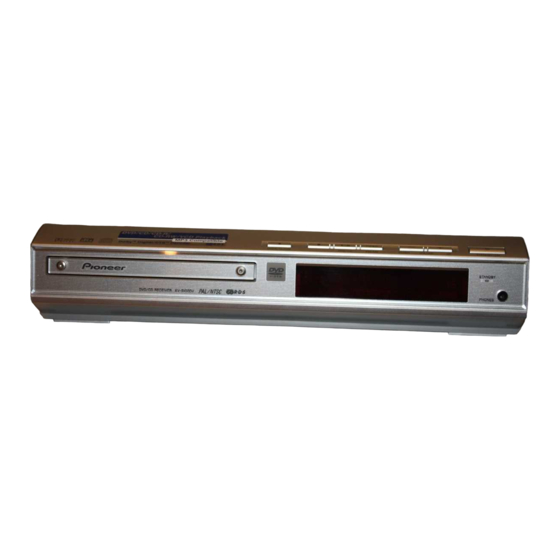
Page 90: Panel Facilities And Specifications
XV-S100DV 8. PANEL FACILITIES AND SPECIFICATIONS 8.1 PANEL FACILITIES Front Panel 1 Disc tray 7 VOLUME UP press to raise the volume 2 0 OPEN/CLOSE press to open/close the disc tray 8 STANDBY/ON 3 7 (stop) 9 STANDBY indicator lights when the system is in... - Page 91 XV-S100DV Remote Control Unit y 3 Cursor right u SOUND i ∞ Cursor down o RETURN ; 7 Stop a PLAY/PAUSE 6 s SYSTEM DISP d 1 | e STEP/SLOW f ¡ | E STEP/SLOW g 4 | –PREV | –FOLDER h ¢...
-
Page 92: Specifications
XV-S100DV 8.2 SPECIFICATIONS Amplifier Section Power Supply Section Power requirements ......AC 220 V to 230 V, 50/60 Hz Continuous power output (DIN) .......... AC 230 V, 50/60 Hz (UK model only) Front .............. 18 W, per channel (1 kHz, 1 % T.H.D., 6 Ω) Power consumption ..............