Advertisement
Quick Links
Predator 60/ 70
SE & Max 90
MAIN BLADES
MAIN BLADES
MAIN BLADES
MAIN BLADES
MAIN BLADES
MAIN ROTOR SPAN
MAIN ROTOR SPAN
MAIN ROTOR SPAN
MAIN ROTOR SPAN
MAIN ROTOR SPAN
TAIL ROTOR SPAN
TAIL ROTOR SPAN
TAIL ROTOR SPAN
TAIL ROTOR SPAN
TAIL ROTOR SPAN
OVERALL LENGTH
OVERALL LENGTH
OVERALL LENGTH
OVERALL LENGTH
OVERALL LENGTH
HEIGHT
HEIGHT
HEIGHT
HEIGHT
HEIGHT
ENGINE
ENGINE
ENGINE
ENGINE
ENGINE
Century Helicopter Products
SPECIFICATIONS
Designed and Developed in USA
2nd Edition, Copyright June 2003. All rights reserved.
Instruction
Manual
60/70
60/70
60/70 SE
60/70 SE
60/70
60/70
60/70
60/70 SE
60/70 SE
60/70 SE
6 9 0 m m
6 9 0 m m
6 9 0 m m
6 9 0 m m
6 9 0 m m
7 0 0 m m
7 0 0 m m
7 0 0 m m
7 0 0 m m
7 0 0 m m
60.6 in
60.6 in
60.6 in
60.6 in
60.6 in
60.6 in
60.6 in
60.6 in
60.6 in
60.6 in
10.5 in
10.5 in
10.5 in
10.5 in
10.5 in
10.5 in
10.5 in
10.5 in
10.5 in
10.5 in
54.5 in
54.5 in
54.5 in
54.5 in
54.5 in
54.5 in
54.5 in
54.5 in
54.5 in
54.5 in
17.2 in
17.2 in
17.2 in
17.2 in
17.2 in
17.2 in
17.2 in
17.2 in
17.2 in
17.2 in
60 ~ 70
60 ~ 70
60 ~ 70
60 ~ 70
60 ~ 70
60 ~ 70
60 ~ 70
60 ~ 70
60 ~ 70
60 ~ 70
Max 90
Max 90
Max 90
Max 90
Max 90
7 2 0 m m
7 2 0 m m
7 2 0 m m
7 2 0 m m
7 2 0 m m
62.9 in
62.9 in
62.9 in
62.9 in
62.9 in
11.2 in
11.2 in
11.2 in
11.2 in
11.2 in
55.7 in
55.7 in
55.7 in
55.7 in
55.7 in
18.2 in
18.2 in
18.2 in
18.2 in
18.2 in
80 ~ 90
80 ~ 90
80 ~ 90
80 ~ 90
80 ~ 90
Advertisement

Subscribe to Our Youtube Channel
Related Manuals for Century Helicopter Products Predator 60


Summary of Contents for Century Helicopter Products Predator 60
-
Page 1: Instruction Manual
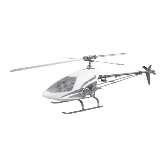
Predator 60/ 70 Instruction SE & Max 90 Manual SPECIFICATIONS 60/70 60/70 60/70 SE 60/70 SE Max 90 Max 90 60/70 60/70 60/70 60/70 SE 60/70 SE 60/70 SE Max 90 Max 90 Max 90 MAIN BLADES MAIN BLADES MAIN BLADES... -
Page 2: Pre-Assembly Information
Care has been taken in filling and packing of each bag however mistakes do happen, if there is a parts shortage or missing hardware please contact us at: Century Helicopter Products 523 Sinclair Frontage Road Milpitas, CA 95035 Tel: 1-408-942-9525 www.centuryheli.com... - Page 3 #HI6181 Head Damping #CN2215A O-Rings Silver Head Button #HI6160 SE & Max Rotor Head Block only Press in the damping o-rings into the rotor head block. Bond the threaded stud into the head button using permanent Lubricate with light oil. locktight then apply more permanent locktight and bond into the top of the rotor head block.
- Page 4 M14 Thrust M3x18 Special Socket #CNBB816 Washer Shoulder Screw #HW6001 #CNLR1020 #CNLR1014 #HI6184 Medium Short Ball Main Blade Grip Ball Insert one ball bearing into each end of the main blade grip. Attach the seesaw assembly with one M3x18 special socket Slide the M14 Thrust Washer against the inside bearing.
- Page 5 #HI6009 Cooling Fan Engine centered in #HW6012 Hole for engine Fan Hub govenor mount. magnet. Install the engine into the mount using the correct number of If a governor is planned to be installed, install the magnets shims and ensure that the engine is centered in the mount. Use into the holes already molded into the bottom of the cooling fan.
- Page 6 Clutch #HW6045 Shoe Lower Short Bearing Block (top surface is flat) Assembly #HW6013 Clutch Bell Assembly 10T #HW6013A Clutch Bell Assembly 11T #HW6014 Replacement Clutch Lining Clean the clutchbell and inside of the bearing with alcohol. Apply a small amount of permanent locktight around the top 15mm edge of the aluminum clutchbell where it will contact the Attach the clutch shoe with the M3 button socket bolts using bearing.
- Page 7 #CNLR1014 #HI6032 #HI6031 Short Ball Rear CCPM Lever CCPM 26mm Cyclic Threaded Bellcranks #HI6110 Spacer M3x30 Upper Side Frames Socket Screw Left & Right #CNLR1020 Stepped #HW6000 Medium Standoff Ball #CNBB37 The stepped standoff is positioned with the step against the Install the rear ccpm lever into the upper frames flush with the bearing on the left side, having the mount extend out the ball bearing in the ccpm bellcrank.
- Page 8 M3x10 26mm #HW6112 Socket Screw Threaded Hex Servo Side Standoff M3x12 Frames Socket Screw M3x8 15mm M3x25 Socket Standoffs x 4 Socket Screw & Screw Locknut #HW6112A Battery Tray & Vertical Front Frame Attach two M3x12 Socket screws from the inside of the Attach the servo frames, battery tray and upper frames battery tray at the forward holes and two M3x10 Socket together using M3x25 Socket screws.
- Page 9 M3x25 Socket Screws 17mm #HW6115A Standoff x 4 Rear Lower Frames X-Frame Standoff x 2 #HW6117 Rear X Frame #HW6054 Spacer 26mm Threaded Standoff Before the main gear assembly can be inserted, make sure Attach the X Frame to the lower side frames first using M3x8 that the M10x14x3.5 spacer is positioned on top of the lower Socket screws and locknuts at the lower hole on a flat surface.
-
Page 10: Main Gear
Main gear assembly, slipper or constant drive type. #HW6001 Main Shaft M3 Pin #HW6001 M4x4 Set Screw x 2 Insert the main gear assembly from the side and slide the After the main shaft pin is started, press it in and start main shaft through the upper main shaft bearing block. - Page 11 #HI6020 Cooling Fan Shroud #HW6017 M4x10 Socket Screws & M4x12 Flat washers x 6 #HI6020 M2.6x10 Self Tap M3x8 Self Tap Screws x 2 Screw x 2 Slide the engine assembly in place and install the M4 Socket bolts and washers. Do not locktight these and leave these loose until the clutch is aligned to the clutchbell.
- Page 12 Pushrod E 100mm (center to center) #HI6146 Swashplate Assembly #CNLR1018 Ultra Short Steel Ball Optional metal servo arms #CNLR1019 Long shown. Steel Ball x 2 Pushrod F 116mm (center #CNLR1014 Short to center) Steel Ball x 5 Install throttle servo to the right side frames. Attach the short ball with M2 thread to the carburetor lever arm with M2 nut The double bearing swashplate requires no maintenance.
- Page 13 #HW6001 M5x35 #HI6122 Landing Struts x 2 Shoulder Socket Screw x 2 & M5 Locknut x 2 ~ 1 1/2” [37mm] 60/70 & SE #HI6145 Ball Link Set (26 long & 4 short) M3x4 Set Screws x 4 #HW6192 Upper #HW6123 10mm Linkage Set (6 rods) Landing Skids x 2...
- Page 14 Recessed hole. #HW6075 Tail #HW6074 Spacer Tube - Gear Set Tail Output Shaft Black Gear #HW3073 Tail Output Shaft Black Gear - Tail Output Shaft Silver Gear - Tail Input Shaft Counter-Clockwise Teeth Clockwise Teeth M3x4 Set Screw Looking down on the two tail gears notice that the black gear Align the hole in the black gear over the hole in the end of tail has teeth that are in the opposite direction to the silver gear.
- Page 15 #CNLR1013 x 2 Short Steel Ball #HI3096A Tail M3x4 Set Screw Grips x 2 #CNBB410 x 2 #HW3098A Steel Tail Rotor Hub M3 Locknut x 2 #CNBB49T x 2 Tail rotor #CNBB0930 #CNLR1003 M3x5x0.5 assembly Micro Washer Insert tail rotor grip assembly onto the tail output shaft, Press the M4 bearing into the end, slide the M3 thrust aligning the set screw over the indent in the shaft using bearing (in correct order), micro washer, M3 bearing and...
- Page 16 End Cap Only complete #HW6202 one end Tail Support now! Strut Set - Aluminum #HW6065 Tail Pushrod Set Insert 10mm into grey ball link. Insert the M2 threaded rod 10mm into the grey ball link. Slide the end cap over the carbon tube and make a mark, 60/70 only.
- Page 17 #HI6067 #HI6067 #HI6068 Tail Fin Horizontal Vertical Fin Mount Set M3x35 Socket M3x35 Socket Screws x 2 Screws x 2 60/70 only. Insert the M3 socket screws through the top of the plastic fin and through the top tail fin mount (straight ends). Notice that Insert the M3 socket screws through the front holes in the the bottom fin mount is angled for comparison.
- Page 18 #HI6082 Tail M3x15 Socket Support Bridge Screw, M3x8 #HI6106 Flat Washer x 2 Adjustable Tail & M3 Locknut Guides Tail pushrod with one end Cable Tie x 4 assembled. SE & Max 90 Slide the two tail pushrod clamps over the unfinished end of only.
- Page 19 #HI6133 Windshield #HI6130 Fiberglass Gelcoat Canopy Drill 8-9 holes. Leave the protective coating in place until after it is drilled for mounting screws. Rough cut the windshield leaving 3mm Position the windshield and tape in place. Mark and drill [1/8”] then carefully cut out the windshield following the pilot holes around the windshield edge, centered through the line molded into the winshield.
- Page 20 Predator 60, SE & Max Replacement Parts HI6009 COOLING FAN HW6015 SPLIT COLLET SET (2) - OS/YS HI6020 COOLING FAN SHROUD SET HW6017 ENGINE MOUNT - OS/YS w/SHIMS HI6031 CCPM CYCLIC BELLCRANKS HW6042 MAIN SHAFT BEARING BLOCK w/BEARING HI6032 CCPM ELEVATOR LEVER SET...
Need help?
Do you have a question about the Predator 60 and is the answer not in the manual?
Questions and answers