Table of Contents
Advertisement
Quick Links
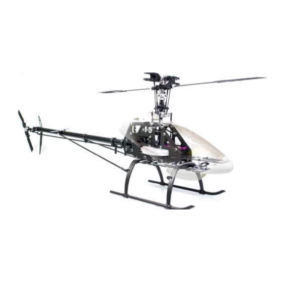
Swift Carbon 550
ELECTRIC R/C HELICOPTER
Kit Instruction Manual
Mechanical Specs:
Main Rotor Blades: 520-550mm
Tail Rotor Blades: 75-85mm
Length: 105cm
Height: 34.4cm
Weight: 1.54kg (configured with brushless motor and servos)
Electronic Specs:
Speed Control: 50-80 Amp
Motor: 900-1250kv (based on battery)
Battery: 4S-6S Li-Po or 12 cell NiMH or NiCd
Main Gear: 96 Tooth
Pinion: 9-15 Tooth
Head Speed: 1600-2100 RPM
Century Helicopter Products
Designed and Developed in USA
1st Edition June 2007 All rights reserved.
Advertisement
Table of Contents

Subscribe to Our Youtube Channel
Related Manuals for Century Helicopter Products Swift Carbon 550


Summary of Contents for Century Helicopter Products Swift Carbon 550
- Page 1 Swift Carbon 550 ELECTRIC R/C HELICOPTER Kit Instruction Manual Mechanical Specs: Main Rotor Blades: 520-550mm Tail Rotor Blades: 75-85mm Length: 105cm Height: 34.4cm Weight: 1.54kg (configured with brushless motor and servos) Electronic Specs: Speed Control: 50-80 Amp Motor: 900-1250kv (based on battery)
-
Page 2: Pre-Assembly Information
1. Introduction Congratulations on your purchase of Century Helicopter Product’s Swift Carbon 550 Kit. The Swift Car- bon 550 is a high performance machine providing the agility and durability that is expected out of a heli- copter of this caliber. The attention and praise by the R/C helicopter community is well deserved as the Century Swift line is unmatched in affordability, quality and performance. -
Page 3: Lithium Polymer Battery Safety
DO NOT store fully charged or discharged batteries in your helicopter. When cutting wires, always cut ONLY ONE WIRE AT A TIME. ** Century Helicopter Products will not be liable for any damages that may occur to your helicopter due to any misuse or mishandling as explained above. - Page 4 3. Required Items for Operation This is the general list of items required to get the Swift Carbon 550 helicopter flying. Century produces a full spectrum of accessories and tools to assemble your helicopter. The Swift Carbon 550 is a electronic cyclic collective pitch mixing type helicopter requiring a standard helicopter radio (the helicopter radio requires eCCPM mixing for this model).
-
Page 5: Before You Begin
4. Before You Begin Every attempt has been made to ease the assembly of your kit, at each step where there are complex instructions there are de- tailed written instructions to walk you through each step. Remember to take a few minutes before each step to carefully examine each process to become familiar with the parts and assembly before beginning that step. - Page 6 6. Assembly Instructions Main Blade Grip Attaches feathering Cap Screw M4x30 shaft on the following page Cap Screw M3x16 (CNM4x30) (CNM4x16) *Raised should Bearing M3x6x2.5 be facing the bearing (CNBB364) Brass Spacer M3x5x3 Spacer M3x5x2 (CNE524) (CNE524) Bell Mixing Arm (CNE524) Linkage Ball (CNLR104)
- Page 7 6. Assembly Instructions Head Block Brass Spacer M8x7x3 Rubber Dampener (CNE522) (CNE520) Feathering Shaft (CNE521A) Button Head M3x6 Linkage Ball (CNM3x6BH) (CNLR1014) Head Block (CNE556-1) Tie Bar (CNE519) Bearing 3x10x4 (CNBB1030) Seesaw Offset Plate (CNE519) Seesaw Shaft (CNE518) Button Head M3x6 (CNM3x6BH) Plastic Spacer M3x6x3 (CNE525)
- Page 8 6. Assembly Instructions Adjusting the Flybar Flybar outer Equal flybar length flat spot on each side Flybar control arms must Flybar outer flat spots align be level with Seesaw. Set with flybar control arms when screws face upward. arms are flush with seesaw. Swashplate and Washout Assembly Washout Base Head Block...
-
Page 9: A-Arm Assembly
6. Assembly Instructions A-Arm Assembly Increase this gap 1. Screw the ball link into the A-arm, make sure it is screwed 3. Use calipers to measure 52mm from all the way in. Back it off so that it is parallel with the face of the one end of the spacer to the other, in- Arm. - Page 10 6. Assembly Instructions Uppper Bearing Block Assembly Upper Bearing Block, Bearing (CNBB1019) Aluminum Upper Bearing Spacer 3.5mm Block (CNE586) (CNE593) Cap Screw M3x8 (CNM3x8CS) M3 Hex Lock Nut Main Frames (CNM3LOCK) (CNE503) CF Main Cap Screws M3x12 Shaft Support (CNM3x12CS) (CNE577) A-Arm Aluminum...
-
Page 11: Motor Mount Assembly
6. Assembly Instructions Lower Bearing Block Assembly 1. Push the bearing (CNBB1019) into the Third Bearing Block (CNE569) and attach to the bottom of the frames, using: Self Tapping Screw M3x10. Make sure your block is facing upwards. Main Frame (CNE503) Self Tapping Screw M3x10 Third Bearing Block... -
Page 12: Main Frame Assembly
6. Assembly Instructions Main Frame Assembly 1. Place the two side frames together with the elevator A-arm assembly in- between them. When looking through the back the elevator bellcrank should be on the left side. Spacer 3.5mm Cap Screw M3x12 (CNE586) (CNM3x12CS) Self Tapping Screw M3x10... - Page 13 6. Assembly Instructions Tail Component Assembly M3 Locknut (R) Gear Box (CNE528) Lock Pin M2x13 Self Tapping Screw M3x8 (CNE529) (CNM3x8ST) Tail Gear (CNE529) Horizontal Fin Tail Shaft (CNE535) (CNE530) M3 Locknut (L) Gear Box Fine Thread Screw M2x10 (CNE528) (CNM2x10PH) Set Screw M3x4 Self Tapping Screws M3x12...
-
Page 14: Tail Transmission Assembly
6. Assembly Instructions Tail Transmission Assembly M4x30 Pin (CNE533) M3x10 Cap Screw (CNM3x10CS) Upper Transmission Case (CNE542) Do not over tighten M3x4 Set Screw Brass Spacer M4x6x.25 (CNLR1006) Transmission Gear (CNE533) Bearing 4x10x4 (CNBB4102) Tailboom (CNE532) Tail Belt Drive Brass Spacer (CN531) M4x6x.25 (CNLR1006) - Page 15 6. Assembly Instructions Tail Gear Box Assembly / Autorotation Hub Assembly Button Head Screw M3x14 (CNM3x14BHCS) Tail Blade Grip M3 Locknut Spacer (CNE552) Tail Blade Grip Linkage Ball (CN540) (CNLR1014) Bearing M3x8x3 Bearing 3x8x3 (CNBB038) (CNBB038) Set Screw M3x4 Cap Screw M3x16 (CNM3x4SS) (CNM3x16CS) Rotor Hub...
-
Page 16: Landing Gear Assembly
6. Assembly Instructions Landing Gear Assembly Cap Screw M3x18 CNC Switch Plate (CNM3x18CS) Standoffs (CNE585) CF Switch Plate Main Frame Braces (CNE572) (CNE584) Cap Screw M3x8 Landing Struts (CNM3x8CS) (CNE512) CF Battery Support Plate (CNE514) M3 Locknut M3 Locknut Button Head Cap Set Screw M3x4 Screw M3x8 (CNM3x4SS) -
Page 17: Assembling The Components
7. Putting Together Your Model Assembling the Components After completing the previous steps, the following instructions are for putting together the sub-assemblies. Please follow the instructions and any hints along the way to ensure that you have a properly flying model. H Spacer Plate (CNE590) Look at gear mesh... - Page 18 7. Putting Together Your Model Servo Linkage Lengths 1) Before proceeding to measure and install the pushrods, make sure you have adjusted the flybar to it’s optimal level (flybar paddles flat and parallel to the ground). Adjust the flybar until the outer flat spots align with the set screws in the flybar control arms (set screws facing Linkage: bell...
- Page 19 All servo arms must be set with linkages as pictured at 90 degree angles. All servos mount with M2.5x12 self tapping screws, M2 servo balls and M2 Nuts. IMPORTANT: Century logo on all ball links must face OUTWARD as pictured. Linkage:...
- Page 20 8. Installing and Adjusting Control Components CCPM Servo Guidelines The goal in the end after all the servos are mounted is to have the swashplate sit level or at 90 degrees to the main shaft and have the swashplate move equally fore, aft and side to side. The swashplate will also travel up and down as the three servos work together.
- Page 21 8. Installing and Adjusting Control Components Setting Tail Rudder Pushrod & Blades 1) When setting up the pitch of the tail blades, the tail pitch plate should be first set in the middle position of the tail rotor shaft. The tail blades should have no pitch in that position. Tighten the tail rotor blades until the blade grips hold firm yet soft enough so that the tail blades can still fold back in the event of a blade strike.
-
Page 22: Final Preparations
Preparing, Mounting & Tracking The Main Rotor Blades The Main Rotor Blades are not included in Swift Carbon 550 kit. Please refer to your blades instructions for proper care and storage of your blades. In the event of a crash-landing, discard rotor blades. Scuffs or marks on the blade tips may be the only visible damage however there is no method for inspecting the internal structure of the rotor blades for stress cracks which can cause total blade failure at an unpredictable time. - Page 23 Preparing, Mounting & Tracking The Main Rotor Blades (1) The Swift Carbon 550 does not come with main rotor blades. Please refer to the instructions included with your blades (must be purchased separately and are not included with the Swift Carbon 550 kit).
-
Page 24: Setup And Adjustment
10. Setup and Adjustment Final Adjustments - Radio Setup Now that the servo installation into the helicopter is finished the following pages should be reviewed. As various types of radios can be used to setup the helicopter, some of the following information may not apply. Pitch Curve Adjustment Servo Direction (Servo Reversing) The following chart shows the values for the collective pitch... - Page 25 11. Final Preparations Final Adjustments - Tail Rotor Setup What separates airplane radio equipment from the helicopter version is in the control of the individual curves discussed earlier and in the Revo-mixing*. Take a moment to consider the helicopter hovering in front of you. Nose rotates left at hover Nose rotates right at hover Problem: Not enough pitch in...
- Page 26 12. Pre-Flight Basic Hovering When all is set, ready and checked, attach your training gear/pod and plug in your battery. Place the helicopter pointing into the wind and stand behind the model about 15’ away. Always watch the nose of the helicopter, move the rudder left and the nose will move left. Start by increasing the throttle slowly until the helicopter rises 2-6 inches off the ground then set it back down.
-
Page 27: Replacement Parts
13. Replacement Parts CNE501 CNE508SL CNE510 CNE502 CNE510A Canopy Standoffs & Solid Main Shaft - Triple Main Gear With Auto- CCPM Bellcrank Set Main Gear Only Grommets Bearing rotation Hub CNE510B CNE514 CNE511 CNE512 CNE513 Auto-rotation Hub & Carbon Fiber Upper Shaft Collar Landing Struts Landing Skids... - Page 28 13. Replacement Parts CNE536A CNE539 CNE540 CNE537 CNE538 Carbon Fiber Fin Set Tail Rotor Hub Tail Blade Grips Tail Pitch Slider Tail Pitch Lever CNE543 CNE544 CNE545 CNE541 CNE542 Tail Boom Tail Servo Mounts Pushrod Set Tail Rotor Blades Tail Transmission Support Set Gear Box CNE553...
- Page 29 14. Replacement Parts CNE587 CNE588 CNE589 CNE591 CNE590 Motor Mount Bell Crank Elevator Plate Standoffs Driven Tail Hub Transmission Box Spacer (2) Spacer (2) Spacer (2) CNBB364 CNBB364 CN2217S CNE592 CNE593 Tail Pitch Lever CCPM Bell Crank Silver Screw Caps Tail Hub Spacer Upper Bearing Block Bearing (4)
- Page 30 Use this table as a guide, your setup and flight conditions will make these results fluctuate. For ultimate performance with head speeds reaching close to 2000rpm, Century recommends the use of high quality flight packs with at least 20C constant discharge rate.
Need help?
Do you have a question about the Swift Carbon 550 and is the answer not in the manual?
Questions and answers