Table of Contents
Advertisement
Quick Links
Advertisement
Table of Contents

Related Manuals for Biddle DF


Summary of Contents for Biddle DF
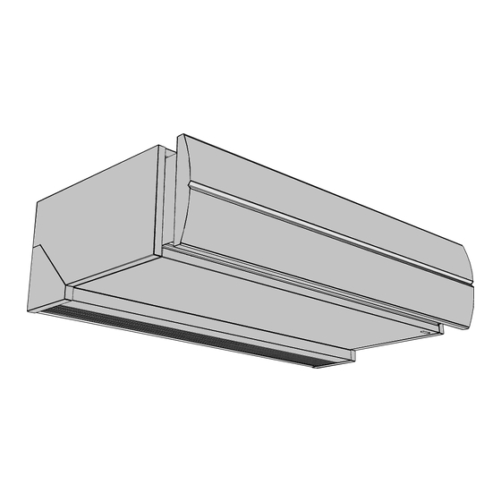
- Page 1 Manual Comfort Air Curtain Model DF English Version 2.0 Original Manual...
-
Page 2: Table Of Contents
Powering up and testing Operation General Starting and stopping Adjusting the strength of the air curtain Adjusting heating Maintenance Cleaning the unit Scheduled maintenance Faults Safety instructions Resolving simple problems Troubleshooting Service Safety instructions Access Fuses Temperature cut-out Biddle control cable composition en-2... -
Page 3: Introduction
. . Introduction About this manual This manual describes the installation, operation and mainte- nance of the Model DF Comfort air curtain. The manual also provides instructions and information about servicing. How to read this manual 1.2.1 Marginal symbols used in the manual... -
Page 4: About The Unit
NTRODUCTION OMFORT URTAIN 1.2.2 Pictograms used on the unit and in the manual The following pictograms indicate potential risks or hazards. The same pictograms will also be found on the unit. Pictograms ICTOGRAM ESCRIPTION You are entering an area of the unit containing live components. Accessible to qualified maintenance staff only. - Page 5 On request, versions can be supplied for other applications. Warning: Applications other than those described above are not considered to be an intended use. Biddle assumes no responsibility for damage or injury resulting from applications other than the intended use. The intended use also implies observance of and compliance with the instructions in this manual.
- Page 6 NTRODUCTION OMFORT URTAIN Different combinations may arise. Explanation of the type code series air curtain range small medium large unit size 100, 150, 200, 250 discharge length (cm) heating hot water electrical zonder verwarm- (Ambient) mounting method fee-hanging model cassette model recessed model 1.3.3 Type plate The type plate can be found on top of the unit.
-
Page 7: Restrictions On Use
1.3.5 Modifications and changes No changes or modifications may be made to the unit which could influence its safety without the approval of Biddle. The CE mark is no longer valid if the unit has been modified or changed in any way. -
Page 8: Safety Instructions
1.4.3 Application limitations with water heating Application limitations for units with water heating Heating medium water with max. 20% glycol Max. water supply DF S-W, M-W: 90 °C temperature DF L-W: 70 °C Max. air discharge DF S-W, M-W: 70 °C temperature DF L-W: 45 °C... - Page 9 DF M ANUAL NTRODUCTION Caution: In exceptional situations, water may run out of the unit. Therefore do not place anything under the unit that could be damaged as a result. 1.5.2 Installation, maintenance and service Danger: The unit may be opened by qualified technical staff only.
-
Page 10: Installation
Immediately report any defects to the supplier. General working method 2.3.1 Sequence of operations Biddle recommends working as follows when installing the Comfort Air Curtain: 1. Mount the unit. 2. For water-heated models: connect the unit to the central heating system. -
Page 11: Suspending Up The Unit
DF M ANUAL NSTALLATION 6. Turn the mains power supply on and check that the unit is working properly. General instructions Some sections of this section only apply to certain models. Where this is the case, it will be indicated. If no specific model is referred to, the description applies to all models. - Page 12 1. Position the four M8 screw threads. Make sure the thread rods are perpendicular. Dimensions for free-hanging and recessed units. SIZE TYPE DIMENSIONS all DF F, R as needed all DF F, R 35 mm all DF F, R 290 mm...
-
Page 13: Connecting The Unit To The Central Heating System
TYPE DIMENSIONS DF 100-C 1012 mm DF 150-C 1512 mm DF 200-C 2012 mm DF 250-C 2512 mm all DF C 705 mm DF 100-C 937 mm DF 150-C 1437 mm DF 200-C 1937 mm DF 250-C 2437 mm all DF C 641 mm 2. - Page 14 • Keep the connectors 1 in place by using pliers when con- necting the pipes. • Biddle recommends inserting a valve and a bleed on both pipes close to the unit. Application limitations for units with water heating Heating medium water with max.
-
Page 15: Connecting The Mains Supply
DF M ANUAL NSTALLATION 3. Connect the valve to Terminal Block 1 as shown in the electrical diagram. 4. Open the valve manually using the handle (Position ‘MAN’). 5. Fill and bleed the system. 6. Check the connections for leaks. - Page 16 NSTALLATION OMFORT URTAIN • If the unit has not been fitted with a power cable and plug: Connect the unit to the mains using a power cable (not supplied). Maximum ratings are specified on the type plate. It must be possible to interrupt the power supply to the unit.
- Page 17 DF M ANUAL NSTALLATION AXIMUM CURRENT ON AXIMUM FUSE VALUE L1, L2 TYPE PLATE <= 80 A 100 A <= 102 A 125 A Note: Multiple units may only be served by a common fuse is their total current consumption is less than 10A.
-
Page 18: Installing The Control Panel And External Controls
- The control cable between the control panel and the connected unit may not be any longer than 30 m. Note: Use Biddle control cables only (Type RJ4). Standard modular telephone cable is not suitable. See also: 2.7.6 "Multiple units operated from one control panel" on page 21 2.7.2 Control panel settings... - Page 19 DF M ANUAL NSTALLATION Control panel settings OSITION OSITION FACTORY SETTING unit remains turned off unit continues running in after supply voltage the same mode after interruption supply voltage interrup- tion fans continue running as fans do not run if heating...
- Page 20 NSTALLATION OMFORT URTAIN 2.7.4 Fault signal output A building management system (BMS) can be connected to the output. • The connector is located on the control PCB (HEALTHY connector). Output operation 24 VDC unit configured as a normal unit no power sup- temperature cut-out has turned the ply voltage heating off or the unit is not being pow-...
- Page 21 2.7.6 Multiple units operated from one control panel • A maximum of eight units may be connected to a single control panel. • Units are daisy chained using Biddle control cables and Connectors and . • The total length of the control cables between connected units may not be any longer than 30 m.
- Page 22 NSTALLATION OMFORT URTAIN You can connect one or more of these units to a single con- trol panel in combination with other units. The following applies in this regard: • A unit with two control PCBs counts as two units. •...
- Page 23 7. Replace the front plate onto the rear plate. See also: 2.7.2 "Control panel settings" on page 18 "Biddle control cable composition" on page 40 2.7.8 Connecting control panel to unit The control panel is connected to one of the two modular unit connectors (marked with Symbols and ).
-
Page 24: Unit Finishing
NSTALLATION OMFORT URTAIN Unit finishing 2.8.1 Edging For cassette models (Type DF C) only: 1. Make a hole in the ceiling for the unit. Dimensions of hole and suspension for cassette model SIZE TYPE DIMENSIONS DF 100-C 1012 mm DF 150-C... -
Page 25: Powering Up And Testing
DF M ANUAL NSTALLATION Discharge section hole dimensions SIZE TYPE DIMENSIONS 90 mm 100-R 970 mm 150-R 1470 mm 200-R 1970 mm 250-R 2470 mm 2. Attach the two angle sections 1 to the unit along the dis- charge openings' edges using the screws supplied. - Page 26 NSTALLATION OMFORT URTAIN Control cables between control panel and unit (or units); If applicable: external control components. 3. Switch the power supply on and/or plug in all connected units. 4. Start up the air curtain using the control panel. 5. Check that air is being blown out of all units across their full width.
-
Page 27: Operation
. . Operation General All regular features can be operated from the control panel. The control panel allows you to: • start and stop the air curtain • set the required heating capacity • set the required room temperature • turn the heating on and off •... -
Page 28: Adjusting The Strength Of The Air Curtain
Button 5: medium fan • Button 6: high fan Note: To achieve maximum climate separation for minimum energy consumption, Biddle recommends selecting the lowest setting at which no draughts occur. Adjusting heating 3.4.1 Manual temperature control In manual mode, heating can be set to full or reduced capac- ity, or turned off. - Page 29 DF M ANUAL PERATION 3.4.2 Automatic temperature control In automatic mode, the unit measures the air inlet tempera- ture and automatically selects the required heating setting to adjust the air temperature to the configured level. • Set the required temperature using Buttons 2 and 3 The LEDs display the temperature in a range from 18 °C to...
-
Page 30: Maintenance
Do not use any solvents. Caution: Make sure no water runs into the unit. Scheduled maintenance Biddle recommends that the following inspection and mainte- nance work is performed by an installer or other technical expert every year. •... -
Page 31: Faults
. . Faults Safety instructions Danger: Internal work may only be performed by qualified technical personnel. Warning: Before you begin: read the safety instructions. See also: "Safety instructions" on page 8 Resolving simple problems If you suspect a fault, first try to resolve the problem using the below table. -
Page 32: Troubleshooting
AULTS OMFORT URTAIN ROBLEM IKELY CAUSE HAT TO DO The unit is not working and the The unit is switched off. Turn the unit on. control panel LEDs are off. The unit has no power supply. Check the power supply: •... - Page 33 DF M ANUAL AULTS Fault rectification (for qualified technical staff only) ROBLEM OSSIBLE AUSE ESOLUTION The control panel works normally The fans are dead. 1. Check the fuse on the control but the unit does not respond. PCB. 2. Check wiring between the con- trol PCB and the fans.
- Page 34 AULTS OMFORT URTAIN ROBLEM OSSIBLE AUSE ESOLUTION Not all connected units are working The control panel is not communi- 1. Check if power is supplied to all (or only partially). cating with one or more connected connected units. units (or with one of the control 2.
- Page 35 DF M ANUAL AULTS ROBLEM OSSIBLE AUSE ESOLUTION The unit (or part of the unit) is For electrically heated units: 1. Check and reset the tempera- blowing cold air. The temperature cut-out has ture cut-out. The LEDs on the control panel are turned the unit (or part of the unit) 2.
-
Page 36: Service
. . Service Safety instructions Warning: Servicing work on the unit may only be performed by qualified technical staff. Warning: Before you begin: read the safety instructions. See also: "Safety instructions" on page 8 Access 6.2.1 Removing the front panel For free-hanging models only: 1. - Page 37 ANUAL ERVICE 6.2.2 Opening the unit For fee-hanging and recessed models with electrical heating (Types DF E-F, E-R) and models without heat- ing (Types DF A-F, A-R): 1. Remove the front panel, if necessary. 2. Remove the inlet grille 4.
- Page 38 ERVICE OMFORT URTAIN For all models: 1. Remove the screws along the edge of the panel. 2. Pull the panel a little forward and take it away. Caution: The entire panel comes free once pulled forward – make sure it does not fall. 6.2.3 Removing the control PCB For all units: 1.
-
Page 39: Fuses
The unit has been fitted with a temperature cut-out to pre- vent overheating. For the following types: DF S-250-E, M-250-E, L-250-E These units have two temperature cut-outs. These protect each section of the unit and can operate independently of one another. -
Page 40: Biddle Control Cable Composition
3. Push back the temperature cut-out pin 1. 4. Check unit connections. 5. Close the unit. 6. Check whether fans are working properly. Biddle control cable composition The control system cable is made up as follows: • Connectors are Type 4P4C. - Page 41 DF M ANUAL ERVICE Manual version 2.0 (26-10-2012) en-41...
- Page 42 Copyright and trademarks All information and drawings contained in this manual remain the property of Biddle and may not be used for any purpose other than that intended, photocopied, duplicated, translated and/or published without prior written permission from Biddle. Biddle’s name is a registered trademark belonging to Biddle BV.
Need help?
Do you have a question about the DF and is the answer not in the manual?
Questions and answers