Table of Contents
Advertisement
Quick Links
Advertisement
Table of Contents

Related Manuals for Biddle SF


Summary of Contents for Biddle SF
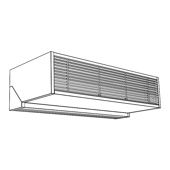
- Page 1 Manual Comfort Air Curtain Model SF Version of guide: 4.0...
- Page 2 Copyright and trademarks All the information and drawings in this manual are the property of Biddle and may not be used (other than for the actual operation of the device), photocopied, duplicated, translated and/or be brought to the attention of third parties without Biddle’s prior written permission.
-
Page 3: Table Of Contents
ANUAL . . . Table of contents Introduction About this manual 1.1.1 General How to use this manual 1.2.1 References in the manual 1.2.2 Symbols used on the unit and in the manual 1.2.3 Related documentation About the unit 1.3.1 Applications 1.3.2 Working... - Page 4 PCB (SFi ) 6.3.1 Introduction 6.3.2 Removing the PCB (SFi W) 6.3.3 Removing the PCB (SFi E) 6.3.4 DIP switches on the PCB Fuses (SFi ) Resetting the high-limit thermostat (SFi E) Composition of Biddle control cable Declaration of conformity...
-
Page 5: Introduction
About this manual 1.1.1 General This manual describes the installation, operation and mainte- nance of the Comfort Air Curtain model SF. The manual also provides instructions and information on service works. The manual provides important directions for the correct and safe operation of the air curtain, and for the prevention of accidents and damages. -
Page 6: Symbols Used On The Unit And In The Manual
NTRODUCTION COMFORT AIR CURTAIN Danger: This indicates actions which are not permitted. Ignoring this warning may lead to serious damage or accidents which may involve bodily injury. The action may be carried out only by qualified staff performing maintenance or repair works. 1.2.2 Symbols used on the unit and in the manual The symbols in Table 1-1 warn against potential risks and/or dangers. -
Page 7: Working
SFi : models with touchpad controller SFs : models with three-speed switch SF W: water-heated models SF E: electrically-heated models SF A: models without heating (ambient) Table 1-2 Type code explained YPE CODE ELE EFERENCE EANING MENT... -
Page 8: Type Plate
• water-side control for fixed discharge temperature. • Biddle control cable, available in various lengths, to link multiple units to one single touchpad controller. • door contact switch. • suspended ceiling finishing kit. -
Page 9: Safety Instructions
ANUAL NTRODUCTION Safety instructions 1.4.1 Operation Warning: It is not allowed to install air filters in the air cur- tain. Warning: Do not put any objects in the in- and outlets. Warning: Do not block the in- and outlets. Warning: ç... -
Page 10: Installation
General working method Working method Biddle recommends the following working method for the installation of the comfort air curtain: 1. Mount the unit (section 2.4). 2. For water-heated models: connect the unit to the central heating system (section 2.5). -
Page 11: Mounting The Unit
ANUAL NSTALLATION General instructions Some parts of this section are applicable only to certain models. Where this is the case, it will be indicated. If no spe- cific model is referred to, the description applies to all models. Note: Make sure you perform all installation operations that are required for your unit. -
Page 12: Suspending And Securing The Unit
SF HP 3.00 m • These heights apply under normal circumstances. If not sure, ask Biddle for advice on the correct height. Note: Mounting the unit at a height exceeding the maximum height may affect the proper working of the unit. -
Page 13: Connecting The Unit To The Central Heating System
When connecting the pipes, hold the connections 1 in place using pliers. Caution: Biddle recommends the inclusion of a valve and a relief valve in both pipes, near the unit. The maximum permissible operating pressure in the hot water circuit is specified on the type plate (see section 1.3.4). - Page 14 NSTALLATION COMFORT AIR CURTAIN 3. Connect the valve to connector 1 according to the wir- ing diagram. 4. Close the unit. 5. Manually open the valve using handle 2. 6. Fill and bleed the system. 7. Check the connections for leaks. 8.
-
Page 15: Connecting The Unit To The Power Supply
7. Close the unit. 8. Set the thermostatic control to the desired discharge tem- perature. Note: Biddle recommends a discharge temperature of 35°C. 9. Fill and bleed the system. 10. Check the connections for leaks. Connecting the unit to the power supply 2.6.1 Connecting water-heated models... - Page 16 NSTALLATION COMFORT AIR CURTAIN • An isolation switch (not supplied) must be fitted between the unit and the power supply. This switch must: contact clearance be all-pole; have a minimum contact clearance of 3 mm; be positioned within 4 m from the right side of the unit. Warning: The unit must NOT be switchable using the power supply cable –...
-
Page 17: Setting A Unit As Master (Sfi , Optional)
ANUAL NSTALLATION Setting a unit as master (SFi , optional) With multiple units operated from one control panel only 2.7.1 Working On delivery, each unit comes set as equal. If you apply multi- ple units with one control panel, the units work independently: •... -
Page 18: Connecting External Controls (Sfi , Optional)
NSTALLATION COMFORT AIR CURTAIN Connecting external controls (SFi , optional) 2.8.1 Input for external control To the input, you may connect a door contact switch and/or a BMS system. The connector is located in the top of the unit. It comes with a bridge in it on delivery. -
Page 19: Installing The Controller
Note: Use only control cables from Biddle. Standard modular telephone cable is not suitable. 1. Interlink the units: Connect the control cable of the unit to which the controller is linked to socket 2, and that of the next unit to socket 1. -
Page 20: Mounting And Connecting The Three-Speed Switch (Sfs )
NSTALLATION COMFORT AIR CURTAIN 2.9.2 Mounting and connecting the three-speed switch (SFs ) Fix the three-speed switch to the wall or to a standard socket. 1. Open the unit (see section 6.2). 2. Connect a 4-core cable to terminal strip 1 according to the wiring diagram. -
Page 21: Integrating The Unit
NSTALLATION 2.10 Integrating the unit The SF is as standard fit for integration into coves or above suspended ceilings. To that end, the discharge section pro- trudes 24mm from the bottom of the unit. If that is not enough, the unit can be supplied with a loose telescopic dis- charge grille instead of the standard mounted discharge grille. -
Page 22: Applying The Edge Finishing
4. Switch the air curtain on using the controller (see sections 3.1 and 3.2.1). 5. Make sure heating is enabled in the controller (only SFi , see section 3.2.3). 6. Feel whether the discharged air stream is getting warm (not for SF A). This may take some time. -
Page 23: Operation
3 = High Recommended air curtain strength To achieve maximum climate separation with minimum energy consumption, Biddle recommends to select the lowest strength at which no draught occurs. Touchpad controller (SFi ) All functions of the SFi can be operated from the touchpad controller. -
Page 24: Switching The Air Curtain On And Off
LEDs on the controller indicate the air curtain strength. Recommended air curtain strength To achieve maximum climate separation with minimum energy consumption, Biddle recommends to select the lowest strength at which no draught occurs. 3.2.3 Enabling or disabling heating Depending on the type of the unit, the heating of the air cur- tain can be controlled automatically and manually. -
Page 25: Enabling Or Disabling Automatic Restart
ANUAL PERATION Automatic temperature control In the Automatic mode, the unit reads the air inlet tempera- ture and automatically selects the heating level required to reach or maintain the preset air temperature level. • Press key 2 to enable or disable automatic temperature control. -
Page 26: Maintenance
Do not use any solvents. Caution: Make sure no water runs into the unit. Scheduled maintenance Biddle recommends to have the following inspection and main- tenance works performed by an installer or other technical expert each year. •... -
Page 27: Faults
ANUAL AULTS . . Faults Safety instructions Danger: Work on the unit’s interior shall be performed by qualified technical staff only. Warning: Before opening the unit, follow the safety instruc- tions in section 1.4. Fault-finding by the user If you suspect a fault, first try to resolve the problem using Table 5-1. - Page 28 AULTS COMFORT AIR CURTAIN Table 5-1 Resolving simple problems ROBLEM IKELY CAUSE HAT TO DO There’s a draught. The air curtain is Off. Switch the air curtain On. The strength of the air curtain is Switch the air curtain to a higher too low.
- Page 29 ANUAL AULTS Tabel 5-2 Remedying faults by the installer ROBLEM IKELY CAUSE HAT TO DO The controller The fans are dead. 1. Check the fuse on the PCB. works normally but 2. Check the wiring between the PCB and the fans. the unit does not The connection 1.
- Page 30 (door contact switch or BMS) in the same way. The unit blows cold SF W: • Check the central heating system. air. No hot water is sup- SFi W: plied to the unit. 1. Check if the valve lets hot water pass through.
- Page 31 ANUAL AULTS Tabel 5-2 Remedying faults by the installer ROBLEM IKELY CAUSE HAT TO DO The unit always The temperature 1. Check connection J3 on the PCB. blows cold air in the sensor is not work- 2. Replace the sensor. Automatic mode.
-
Page 32: Service
Disconnect the power supply (pull plug from socket or move isolation switch to Off). 2. Detach the inlet grille from the unit: Only for SF E and SF A: remove the screws 1 from the grille. Pull the grille 2 forward using the white clamps 3 at the bottom. -
Page 33: Pcb (Sfi )
ANUAL ERVICE PCB (SFi ) 6.3.1 Introduction The unit has one fused PCB. The SFi E and the SFi W house the PCB at different locations. Note: The PCB in your unit may look different from the PCB illustrated opposite. 6.3.2 Removing the PCB (SFi W) 1. -
Page 34: Dip Switches On The Pcb
ERVICE COMFORT AIR CURTAIN 6.3.4 DIP switches on the PCB Warning: NEVER change the settings of the DIP switches, unless instructed otherwise. Caution: If you replace the PCB: set the DIP switches on the new PCB in the same positions as the old PCB. Fuses (SFi ) The unit’s PCB has 2 fuses. -
Page 35: Composition Of Biddle Control Cable
ANUAL ERVICE Composition of Biddle control cable The control cable for Biddle units is different from standard modular telephone cables. The connectors are of the RJ-11 type but the connections are ‘straight’ at both ends of the cable, the core is connected to the same pin. -
Page 36: Declaration Of Conformity
9288 HA Kootstertille THE NETHERLANDS We declare that the following product. Product description: Comfort Air curtain Brand: Biddle Model: Type: SP-100-A/E/W-F ; SF SP-150-A/E/W-F ; SF SP-200- A/E/W-F HP-100-A/E/W-F ; SF HP-150-A/E/W-F ; SF HP-200- A/E/W-F SP-100-A/W-F ; SF SP-150-A/W-F ; SF SP-200 A/W-F HP-100-A/W-F ;...
Need help?
Do you have a question about the SF and is the answer not in the manual?
Questions and answers