
Related Manuals for B&B Electronics Elinx EIRP410-2SFP-T


Summary of Contents for B&B Electronics Elinx EIRP410-2SFP-T
- Page 1 Manual Elinx EIRP410-2SFP-T 8 Ports10/100 PoE with 2 combo 10/100/1000 or 100/1000 SFP Ports Unmanaged Din Rail Ethernet Switch...
- Page 2 EIRP410-2SFP-T Documentation Number: EIRP410-2SFP-T-0912m International Headquarters: 707 Dayton Road Ottawa, IL 61350 USA Phone (815) 433-5100 Website: www.bb-elec.com Sales e-mail: orders@bb-elec.com Technical Support: support@bb.elec.com – European Headquarters B&B Electronics Westlink Commercial Park Oranmore, Co. Galway, Ireland Phone +353 91-792444 Website: www.bb-europe.com Sales e-mail: sales@bb-europe.com Technical Support: support@bb-europe.com Original –...
-
Page 3: Table Of Contents
Table of Contents INTRODUCTION ........................1 The EIRP410-2SFP-T is an industrial Managed Ethernet switch that has 8 10/100TX PoE ports and 2 10/100/1000T/Mini-GBIC Combo ports..........................1 Features ....................................1 Package Contents ................................... 2 HARDWARE DESCRIPTION ....................3 Physical Dimension ................................3 Front Panel ..................................... -
Page 5: Introduction
Introduction The EIRP410-2SFP-T is an industrial Managed Ethernet switch that has 8 10/100TX PoE ports and 2 10/100/1000T/Mini- GBIC Combo ports. Features • System Interface/Performance RJ-45 ports support Auto MDI/MDI-X Function Embedded 8-ports PoE SFP (Mini-GBIC) supports 100/1000 Dual Mode Store-and-Forward Switching Architecture Back-plane (Switching Fabric): 5.6Gbps 1Mbits Packet Buffer... -
Page 6: Package Contents
Package Contents • 8 Ports10/100 PoE with 2 combo 10/100/1000 or 100/1000 SFP Ports Industrial Switch • User manual • Pluggable Terminal Block • 2 wall mount plates and 6 screws • One DIN-Rail (attached on the switch) 8 10/100TX + 2 10/100/1000T/100/1000 SFP Combo with 8 PoE Injectors Industrial Switch User Manual block connector Wall Mount Plate... -
Page 7: Hardware Description
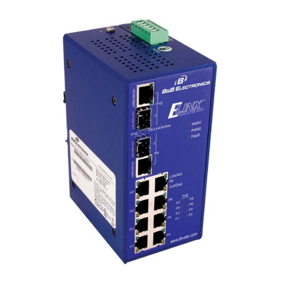
Hardware Description The following information is an introduction to the Industrial switch’s hardware spec, port, cabling information, and wiring installation will be described. Physical Dimension 8 Ports10/100 PoE with 2 combo 10/100/1000 or 100/1000 SFP Ports Industrial Switch dimension (W x D x H) are 72mm x 105mm x 152mm Front Panel The Front Panel of the 8 Ports10/100 PoE with 2 combo 10/100/1000 or 100/1000 SFP Ports Industrial Switch is shown... -
Page 8: Top View
Top View The top view of the 8 Ports10/100 PoE with 2 combo 10/100/1000 or 100/1000 SFP Ports Industrial Switch has one terminal block connector of two DC power inputs. Top View of the PoE Injectors Industrial Switch Manual Documentation Number: EIRP410-2SFP-T-0912m B&B Electronics Mfg Co Inc –... -
Page 9: Led Indicators
LED Indicators The diagnostic LEDs located on the front panel of the industrial switch provide real-time information of operation and status. The following table provides the description of the LED status and their meanings for the switch. Status Meaning Green Power 1 is active PWR1 No power inputs... -
Page 10: Ports
Ports RJ-45 ports The RJ45 copper ports support auto MDI/MDIX operation. This feature allows network connections to computers, servers, or other switches using straight-through or crossover cables (See Figure below). Straight-through cable connections: pins 1, 2, 3 and 6, at one end of the cable, are connected straight-through to pins 1, 2, 3 and 6 at the other end of the cable. The table below shows the 10BASE-T/100BASE-TX MDI and MDI-X port pin outs. - Page 11 Cross Over Cable Schematic Manual Documentation Number: EIRP410-2SFP-T-0912m B&B Electronics Mfg Co Inc – 707 Dayton Rd - PO Box 1040 - Ottawa IL 61350 - Ph 815-433-5100 - Fax 815-433-5104 – www.bb-elec.com B&B Electronics – Westlink Commercial Park – Oranmore, Galway, Ireland – Ph +353 91-792444 – Fax +353 91-792445 – www.bb-europe.com...
-
Page 12: Mini-Gbic Combo Port
2 Mini-GBIC combo port 2 auto-detect combo Giga ports — RF45 or fiber. The gigabit Ethernet ports are shared with the mini-GBIC ports. RJ45 UTP (Gigabit Ethernet) ports can operate in half/full-duplex modes and work at speeds of 10/100/1000Mbps that support auto-sensing technology to enable each port to detect the connecting speed. - Page 13 Figure 2.9: Transceiver Inserted Second, insert the fiber cable LC connector into the transceiver. Figure 2.10: LC connector to the transceiver To remove the LC connector from the transceiver, press the upper side of the LC connector to release from the transceiver and pull it out.
- Page 14 Figure 2.11: Remove LC connector Second, push down the metal loop and pull the transceiver out by the plastic handle. Figure 2.12: Pull out from the transceiver Manual Documentation Number: EIRP410-2SFP-T-0912m B&B Electronics Mfg Co Inc – 707 Dayton Rd - PO Box 1040 - Ottawa IL 61350 - Ph 815-433-5100 - Fax 815-433-5104 – www.bb-elec.com B&B Electronics –...
-
Page 15: Wiring The Power Inputs
Wiring the Power Inputs Wiring the Fault Alarm Contact The fault alarm contact wired to pins 3 and 4 of the terminal block connector as the picture shows below. When the wires are inserting the connected device will detect the fault status. The fault status includes power failure or port link failure. Once one of the mentioned states occur an open circuit will exist. - Page 16 Manual Documentation Number: EIRP410-2SFP-T-0912m B&B Electronics Mfg Co Inc – 707 Dayton Rd - PO Box 1040 - Ottawa IL 61350 - Ph 815-433-5100 - Fax 815-433-5104 – www.bb-elec.com B&B Electronics – Westlink Commercial Park – Oranmore, Galway, Ireland – Ph +353 91-792444 – Fax +353 91-792445 – www.bb-europe.com...
-
Page 17: Mounting Installation
Mounting Installation DIN-Rail Mounting The DIN-Rail is installed at the factory and maybe removed if needed. Rear Panel of the switch DIN-Rail First, insert the top of the DIN-Rail into the track. Manual Documentation Number: EIRP410-2SFP-T-0912m B&B Electronics Mfg Co Inc – 707 Dayton Rd - PO Box 1040 - Ottawa IL 61350 - Ph 815-433-5100 - Fax 815-433-5104 – www.bb-elec.com B&B Electronics –... - Page 18 Lightly push the DIN-Rail into the track. Check the DIN-Rail to insure proper fit. To remove the industrial switch from the track, reverse steps above. Manual Documentation Number: EIRP410-2SFP-T-0912m B&B Electronics Mfg Co Inc – 707 Dayton Rd - PO Box 1040 - Ottawa IL 61350 - Ph 815-433-5100 - Fax 815-433-5104 – www.bb-elec.com B&B Electronics –...
-
Page 19: Wall Mount Plate Mounting
Wall Mount Plate Mounting 1. Remove the DIN-Rail from the industrial switch. 2. Install the wall mount plate on the rear panel of the industrial switch. Manual Documentation Number: EIRP410-2SFP-T-0912m B&B Electronics Mfg Co Inc – 707 Dayton Rd - PO Box 1040 - Ottawa IL 61350 - Ph 815-433-5100 - Fax 815-433-5104 – www.bb-elec.com B&B Electronics –... -
Page 20: Network Application
Network Application This segment provides the samples to help user have more actual idea of industrial switch application. For a sample application of the industrial switch, see the figures below. Manual Documentation Number: EIRP410-2SFP-T-0912m B&B Electronics Mfg Co Inc – 707 Dayton Rd - PO Box 1040 - Ottawa IL 61350 - Ph 815-433-5100 - Fax 815-433-5104 – www.bb-elec.com B&B Electronics –... -
Page 21: Troubleshooting
Troubleshooting • Verify that you are using the appropriate power supply adapter. Do not use the power adapter with DC output higher than the power rating of the device. • Select the proper UTP/STP cable to construct your network. Use unshielded twisted-pair (UTP) or shielded twisted-pair (STP) cable for RJ-45 connections: 100Ω... -
Page 22: Technical Specification
Technical Specification IEEE 802.3 10Base-T Ethernet IEEE 802.3u 100Base-TX/FX IEEE802.3ab 1000Base-T Standard IEEE802.3z Gigabit fiber IEEE802.3x Flow Control and Back Pressure IEEE802.3af Power over Ethernet CSMA/CD Protocol 14,880 pps for 10Base-T Ethernet port Transfer Rate 148,800 pps for 100Base-TX/FX Fast Ethernet port 1,488,000 pps for Gigabit Fiber Ethernet port Packet Buffer 1Mbits... - Page 23 Min. TX Output: Multi mode: -20 dBm Single mode: 0 to 40 km, -5 dBm; 0 to 80 km, -5 dBm Max. TX Output: Multi mode: -14 dBm Single mode: 0 to 40 km, 0 dBm; 0 to 80 km, 0 dBm Sensitivity: -36 to -32 dBm (Single mode);...
- Page 24 Safety CE/EN60950-1 IEC60068-2-32 (Free fall) Stability testing IEC60068-2-27 (Shock) IEC60068-2-6 (Vibration) Manual Documentation Number: EIRP410-2SFP-T-0912m B&B Electronics Mfg Co Inc – 707 Dayton Rd - PO Box 1040 - Ottawa IL 61350 - Ph 815-433-5100 - Fax 815-433-5104 – www.bb-elec.com B&B Electronics –...
Need help?
Do you have a question about the Elinx EIRP410-2SFP-T and is the answer not in the manual?
Questions and answers