Table of Contents
Advertisement
Advertisement
Table of Contents
Troubleshooting

Related Manuals for LifeFitness 95T ELEVATION SERIES


Summary of Contents for LifeFitness 95T ELEVATION SERIES
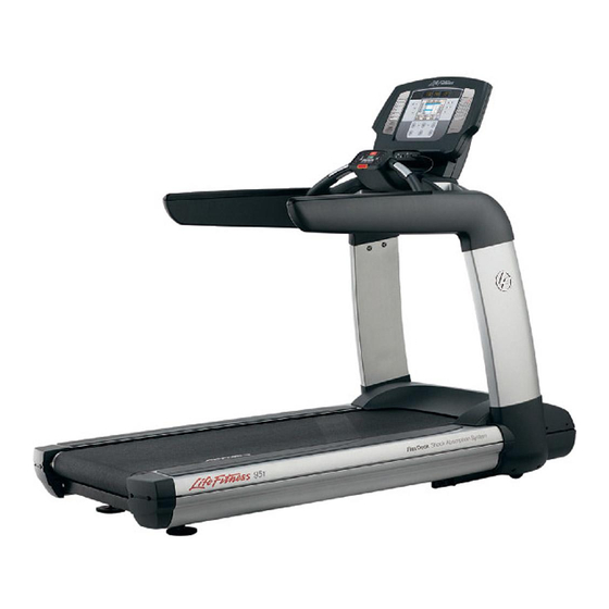
- Page 1 95T ELEVATION SERIES TREADMILLS Service Manual M051-00K65-A003 11/16/09...
-
Page 2: Table Of Contents
Table of Contents Table of Contents Introduction Using This Manual Contact Information System Level Troubleshooting Preparation Required Service Tools Specialty Tools Maintenance Preventive Maintenance Schedule Modules Drive Motor (DS) System Component Problem Symptoms Table How To’s Base Frame Electronics (BE) Theory of Operation System Components Problem Symptom Table... -
Page 3: Table Of Contents
Table of Contents Theory of Operation System Components Problem Symptom Table Troubleshooting Flow Diagrams How To’s Electrical Wiring Diagrams Heart Rate System (HR) ® Lifepulse Theory of Operation System Components Problem Symptom Table How To’s Stride (Walking) System (SS) Theory of Operation System Components Problem Symptom Table How To’s... - Page 4 Table of Contents iPod ® Test Test Engineering System Test Menu 2 Stride Sensor Test (TR only) External Serial EE Test CSAFE Network Test or Status CSAFE Loopback Test Information Menu Information Statistics Software Versions Main Motor Information (TR Only) Lift Motor Information (TR Only) Belt / Deck Information (TR Only) Date and Time Information...
-
Page 5: Introduction
Introduction... -
Page 6: Using This Manual
Introduction Using This Manual M051-00K65-A003 This service manual provides safe and efficient test and service procedures for the 95T Elevation Series treadmills. The service manual is arranged in the following sections: Introduction This section provides the usage guidelines, contact information, technical specifications and glossary of terms used in this manual. Preparation This section provides the list of service tools required to perform various service operations described in this manual. Maintenance This section describes a suggested preventive maintenance schedule for the equipment. Theory of Operation This section describes the working principle of a treadmill, described for various components such as mechanical, electrical and software. -
Page 7: Contact Information
Location of model and Location of model and serial numbers serial numbers Corporate Headquarters 5100 River Road, Schiller Park, Illinois 60176 U.S.A. Toll-Free: 800.735.3867 (within U.S.A., Canada) Tel: (847) 288 3300 Fax: (847) 288 3703 Global Website: www.lifefitness.com International Offices AMERICA’S NORTH AMERICA LATIN AMERICA & CARIBBEAN* Life Fitness Inc. Life Fitness Inc. 5100 N River Road, Schiller Park, IL 60176 U.S.A. 5100 N River Road, Schiller Park, IL 60176 U.S.A. - Page 8 Tel: (+31) 180 646 666 Tel: (+32) 87 300 942 Fax: (+31) 180 646 699 Fax: (+32) 87 300 943 Service Email: internationalservicesupport@lifefitness.com Service Email: internationalservicesupport@lifefitness.com Sales/Marketing Email: marketing.benelux@lifefitness.com Sales/Marketing Email: marketing.benelux@lifefitness.com Operating Hours: 9.00h-17.00h (CET) Operating Hours: 9.00h -17.00h (CET) UNITED KINGDOM & IRELAND ALL OTHER EMEA COUNTRIES &...
-
Page 9: System Level Troubleshooting
Introduction System Level Troubleshooting M051-00K65-A003 SYMPTOM POSSIBLE CAUSE SECTION PAGE Belt not moving Treadmill not powered Base Frame Electronics BE 8 Console operation Console and Activity Zone CA 11 Motor does not start upon Base Frame Electronics BE 8 workout start Noise and vibration From the general striding Stride System... -
Page 10: Preparation
Preparation... -
Page 11: Required Service Tools
Preparation Required Service Tools M051-00K65-A003 Unless otherwise specified, these tools are required to perform the service procedures in this manual: 1. Screwdrivers (Phillips and flat blade) 2. Torx bits and drivers 3. Pliers (regular and needle nose) 4. Rubber or dead blow mallet Snap ring pliers (internal and external) 6. E-ring tools 7. Socket wrenches (English and metric) 8. Ratchet wrenches (English and metric) 9. Combination, open-end, or box wrenches (English and metric) 10. Allen head wrenches (English and metric) 11. Strap wrench 12. Mini flashlight 13. Scribe or ink pen 14. Straight edge 15. Nut driver (1/4” drive socket set) 16. Removable thread locking compound – e.g. Loctite® 242 or 243 17. Break Free® 18. Cord or twine 19. Diagonal cutters (small and medium) 20. 2 blocks (e.g., scrap 4” X 4” [101mm x 101mm] wood) 21. Multimeter with test leads 22. Tape measure... -
Page 12: Specialty Tools
Preparation Specialty Tools M051-00K65-A003 Life Fitness Tools: 1. Bearing removal toolkit p.n., p.n. bearing toolkit NOTE: Part numbers are subject to change. -
Page 13: Maintenance
Maintenance... - Page 14 Maintenance Preventive Maintenance Schedule M051-00K65-A003 ITEM WEEKLY MONTHLY QUARTERLY BIANNUALLY ANNUALLY Hardware Inspect for loose or damaged hardware. Replace if necessary. Reapply Loctite 242/243 as needed. Tighten torque bolts to recommended specifications in the Service Manual. Console / Clean with Activity Zone a mild soap overlay and water,...
-
Page 15: Preventive Maintenance Schedule
Maintenance Preventive Maintenance Schedule M051-00K65-A003 ITEM WEEKLY MONTHLY QUARTERLY BIANNUALLY ANNUALLY Hardware Inspect for loose or damaged hardware. Replace if necessary. Reapply Loctite 242/243 as needed. Tighten torque bolts to recommended specifications. Handlebar Inspect for cracking, color fading, etc. Replace if necessary. Side handrails Inspect for including... - Page 16 Maintenance Preventive Maintenance Schedule M051-00K65-A003 ITEM WEEKLY MONTHLY QUARTERLY BIANNUALLY ANNUALLY Hardware Inspect for loose or damaged hardware. Replace if necessary. Reapply Loctite 242/243 as needed. Tighten torque bolts to recommended specifications. Uprights and Clean with a Inspect for bolts to mount mild soap and loose or to the lower...
- Page 17 Maintenance Preventive Maintenance Schedule M051-00K65-A003 ITEM WEEKLY MONTHLY QUARTERLY BIANNUALLY ANNUALLY Motor Vacuum Inspect flywheel, drive electronic interior compartment pulleys cables, connectors, Lift Motor, motor control board, etc. for damage. Use a nylon brush to remove debris. Replace components as needed. Drive belt Inspect for excessive wear, e.g. cracking, belt debris.
- Page 18 Maintenance Preventive Maintenance Schedule M051-00K65-A003 ITEM WEEKLY MONTHLY QUARTERLY BIANNUALLY ANNUALLY Side shrouds Clean with a mild soap and water, Original Dawn® dishwashing liquid recommended. Inspect for loose hardware. Side extrusions Clean with a mild soap and water, Original Dawn® dishwashing liquid recommended.
-
Page 19: Modules
Modules... - Page 20 Modules DS 1 Drive Motor:System Component M051-00K65-A003 Set Screw Over Key (51-71 in-lbs) (9-13 ft-lbs) (9-13 ft-lbs) [59-82 kg-cm] [12-17 N-m] [12-17 N-m] QTY 4 (Bolt for -03 models or higher) QTY 4 Flat Washer Drive Belt Motor QTY 4 Shoulder Washer QTY 4 Idler Assembly Flywheel...
-
Page 21: Drive Motor (Ds)
Modules DS 2 Drive Motor:Problem Symptoms Table M051-00K65-A003 SYMPTOM POSSIBLE CAUSE SECTION PAGE Drive motor does not Drive motor cable Check drive motor cable BE 7 operate. connection to controller. connection to controller faulty. BE 12 Wrong motor controller for Install proper motor controller. -
Page 22: How To's
Modules DS 3 Drive Motor:How To’s M051-00K65-A003 REMOVAL OF DRIVE MOTOR 1. Turn the treadmill power switch off. 2. Unplug the line cord from the wall outlet. 3. Disconnect the cables between the drive motor and the motor controller. 4. Insert a flat blade screwdriver into the slotted end of the idler bracket. 5. Raise idler bracket just enough to insert a screwdriver or an Allen wrench into the access hole of the idler bracket. This will keep it in a raised position. - Page 23 Modules DS 4 Drive Motor:How To’s M051-00K65-A003 16. Install the new drive motor. Reuse any hardware removed and saved in previous steps. 17. Slide the drive motor pulley onto the motor shaft and install key into pulley and motor shaft keyway. 18. To align the drive motor pulley (sheave) with the front roller pulley: a. Using a straight edge, align the outer face of the drive motor pulley with the outer face of the front roller pulley. b. Slide the drive motor pulley (sheave) in or out on the shaft during alignment. c. Tighten set screw over the key on the drive motor pulley first. Rotate motor pulley by pushing on the flywheel to make sure pulleys have been properly aligned and belt is running true. Tighten second set screw. Roller Pulley Straight Edge Motor Pulley (sheave) 19. Re-install the Idler bracket and drive belt.
-
Page 24: Base Frame Electronics (Be)
Modules BE 1 Base Frame Electronics:Theory of Operation M051-00K65-A003 1. Overview The electronics in the base of Elevation Series treadmills control the main motor and Lift Motor, provides power to the console and monitors the stride sensor. All the circuitry is contained on a single printed circuit board (PCB) assembly which consists of the PCB plus heatsink and bracket. This DSP Board assembly is known as the “DSP controller” since a Digital Signal Processor (DSP) is at the heart of all the control functions of this board. There are two versions of DSP controller used on Elevation series treadmills, one for low voltage (100-120 VAC) and another for high... - Page 25 Modules BE 2 Base Frame Electronics:Theory of Operation M051-00K65-A003 6. Stride Sensor The Stride sensor is a piezoelectric sensor placed under the deck which senses movement of the deck. The voltage coming out of the piezoelectric sensor goes to the DSP controller which has an opto-isolator isolating the stride sensor from the DSP. The DSP monitors this voltage and sends the information to the console where it is used to determine the presence of a user. 7. Console Interface The DSP communicates to the console processor via a two wire serial communications. (Note: JW3 should not be present for Elevation treadmills. Other treadmills which use single wire communication will have JW3 in on the DSP controller). Opto-isolators are provided on the DSP controller to isolate the transmit line and receive line since the ground reference for the DSP circuitry is not the same as that of the console. DSP controller software updates can be performed...
- Page 26 Modules BE 3 Base Frame Electronics:Theory of Operation M051-00K65-A003 10. Connector Connector P1 is a six position female Mate-N-Lock connector for motor. PIN # DESCRIPTION P1-1 Frame P1-2 Phase W P1-3 Phase V P1-4 Phase U P1-5 Not Used P1-6 Not Used Connector P4 is a four position Micro-fit connector for limit switches. PIN # DESCRIPTION P4-1 Zero position switch P4-2 Zero position switch return (GND) P4-3...
- Page 27 Modules BE 4 Base Frame Electronics:Theory of Operation M051-00K65-A003 Connector P7 is a three position Mini-fit Senior connector for input power. PIN # DESCRIPTION P7-1 Line P7-2 Neutral P7-3 Not used Connector P8 is a 2 position Mini-fit Jr. for motor thermal switch. PIN # DESCRIPTION P8-1 Therm1 P8-2 Therm2 Connector P9 is a five position Mini-Fit Jr. connector for console voltage select. PIN # DESCRIPTION P9-1 P9-2 6/8V P9-3 P9-4 P9-5 12V(ESS) Connector P10 is a 3 position C-grid connector for Stride Sensor interface. PIN # DESCRIPTION P10-1...
-
Page 28: System Components
Modules BE 5 Base Frame Electronics:System Components M051-00K65-A003 Motor Controller Main Cable Retaining Bracket Line Cord On/Off Switch... -
Page 29: Problem Symptom Table
Modules BE 6 Base Frame Electronics:Problem Symptom Table M051-00K65-A003 SYMPTOM POSSIBLE CAUSE SECTION PAGE See flow chart. BE 8 No power to treadmill Open or failure in line cord, cables, controller, etc. Insufficient line voltage. SS 3 Maximum speed is reduced Refer Stride System or error message “Cannot Module. attain target speed”. - Page 30 Modules BE 7 Base Frame Electronics:Problem Symptom Table M051-00K65-A003 SYMPTOM POSSIBLE CAUSE SECTION PAGE Error message “Start up Motor unplugged or Verify that the motor error” connector loose. connections are solid. A possible but unlikely Perform a phase test cause would be the user to verify the system or driving the belt at startup.
-
Page 31: Troubleshooting Flow Diagrams
Modules BE 8 Base Frame Electronics:Troubleshooting Flow Diagrams M051-00K65-A003 No Power on Treadmill Switch the Measure line Line voltage at No voltage at outlet Start treadmill to voltage at outlet outlet ok? other outlet Check line cord at outlet and Reseating the Seated property? receptacle at... - Page 32 Modules BE 9 Base Frame Electronics:Troubleshooting Flow Diagrams M051-00K65-A003 Reduce Maximum Speed Measure line Worn belt or Start voltage at outlet deck? Replace belt, Perform belt/ Excess power flip the deck if deck test. indicated? necessary. Problem with Insufficient Check line incoming line voltage voltage? power or not a dedicated line...
- Page 33 Modules BE 10 Base Frame Electronics:Troubleshooting Flow Diagrams M051-00K65-A003 Treadmill Pauses or Reset Randomly Check whether Connect to a the treadmill is On dedicated Start dedicated line, on a dedicated line? see manual line Check power cord at outlet Properly seat the Seated properly? power cord Check ground...
-
Page 34: How To's
Modules BE 11 Base Frame Electronics:How To’s M051-00K65-A003 REPLACEMENT OF LINE CORD 1. Turn the treadmill power switch off. 2. Unplug the line cord from the wall outlet. 3. Lift the front end of the treadmill approximately 4 inches off the floor and place a block of wood underneath both sides to support it. 4. Remove and save the two screws that secure the line cord retaining bracket to the motor pan. 5. Unplug the defective line cord. 6. Install the new line cord, using the screws removed and saved in Step 4. - Page 35 Modules BE 12 Base Frame Electronics:How To’s M051-00K65-A003 REPLACEMENT OF MOTOR CONTROLLER (DSP) 1. Turn the treadmill power switch off. 2. Unplug the line cord from the wall outlet. 3. Remove the top motor cover (See LF 3). 4. Record the cable connection locations. 5. Remove the lower bridge cover (See UF 4). 6. Loosen the three hex nuts that secure the motor controller to the motor pan. 7. Remove and save the two bolts that secure the motor controller bracket to the Lift Motor bracket.
- Page 36 Modules BE 13 Base Frame Electronics:How To’s M051-00K65-A003 REPLACEMENT OF THE ON/OFF SWITCH 1. Turn the treadmill power switch off. 2. Unplug the line cord from the wall outlet. 3. Remove the top motor cover (See 4. Record the location of wire connections to the on/off switch. 5. Disconnect the wires. Use needle nose pliers if necessary. (You may need to remove the motor controller to allow more room to access the on/off switch.). 6. Squeeze the tabs on the top and bottom of the on/off switch and push out from inside the frame.
- Page 37 Modules BE 14 Base Frame Electronics:How To’s M051-00K65-A003 REPLACEMENT OF IEC RECEPTACLE 1. Turn the treadmill power switch off. 2. Unplug the line cord from the wall outlet. 3. Lift the end of the treadmill about four inches off the floor and place blocks of wood under both sides to support it. 4. Remove and save the two screws that secure the line cord retaining bracket to the motor pan. Set the retaining bracket aside. 5. Unplug the line cord form the unit and save. 6. Remove the top motor shroud cover (See 7. Remove the motor controller. 12-18 lb*in IEC Receptacle [13.8-20.7 kg*cm]...
-
Page 38: Electrical Wiring Diagrams
Modules BE 15 Base Frame Electronics:Electrical Wiring Diagrams M051-00K65-A003 DSP Controller Block Diagram DSP Controller Piezo-Electric Stride Sensor Stride Sensor Opto-isolated Console Interface 3 Phase AC Digital Signal Power Supply Power Supply Power Supply Power Supply Power Supply Power Supply Power Supply Power Supply Power Supply... - Page 39 Modules BE 16 Base Frame Electronics:Electrical Wiring Diagrams M051-00K65-A003 DSP Controller Functional Description LED8: 3.3VDC JW10 on P17 P4: Home P7: AC Input P10: Stride Sensor Welded Frame:In LED9: VD SW LED 120V: 3POS Classic Frame:Out P9: PS Jumper 9 & 10 230V: 2POS LED: 8V &...
- Page 40 Modules BE 17 Base Frame Electronics:Electrical Wiring Diagrams M051-00K65-A003 Base Electronics Wiring Diagram...
-
Page 41: Theory Of Operation
Modules LS 1 Lift System: Theory of Operation M051-00K65-A003 The Lift Motor System is comprised of the Lift Motor, the lift frame and the Home Switch. (see page LS-4) In order for the lift system to be operational, the Emergency Stop Switch located on the console area must be properly engaged. The Lift Motor is pinned to the Lift Motor support bracket on the treadmill frame on one end and is pinned on the other end to the lift frame. The Lift Frame is also pinned to the treadmill frame. (see page LS-4) The Lift Motor consists of a gear box, a steel ACME screw and a steel tube. The steel tube has an engineered plastic nut that is fixed on one end of the tube. The ACME screw is pinned to the output gear on the gear box on one end and screws into the nut on the steel tube on the other end. As the ACME screw rotates the steel tube extends or retracts which raises or lowers the treadmill. There are internal limits switches on the gearbox to prevent over-travel. The Lift Motor is programmed to incline the treadmill up to 15% at 0.5% increments. The desired incline is commanded through the incline up or down arrows or through the keypad on the console. When a user first starts the treadmill the Lift Motor will lower the treadmill until the Home Switch is activated (this is 0% incline or level) unless the treadmill is already at 0% incline. If the Home Switch cannot be activated, the console will display a message after a given duration, stating “incline inoperative continue if desired”. -
Page 42: Lift System (Ls)
Modules LS 2 Lift System: System Components M051-00K65-A003 Cross-section View Of Lift System (-01 And -02 Models Only) Cross-section View Of Lift System (-01 And -02 Models Only) Frame Tie Bar Clevis Pin Lift Motor Lift Motor Support Bracket Home Switch Wheel and E-Ring Lift Frame Lift Motor... - Page 43 Modules LS 3 Lift System: System Components M051-00K65-A003 Lift System (-01 And -02 Models Only) Tie Bar Bolt, Flat Washer, Split Washer (4 places) (5-9 ft-lbs) Lift Motor [8-12 N-m] Support Bracket Nut, Flat Washer Clevis Pan (3 places) (9-13 ft-lbs) [12-17.6 N-m] Frame Tie Bar Bolt, Flat Washer...
-
Page 44: Problem Symptom Table
Modules LS 4 Lift System: Problem Symptom Table M051-00K65-A003 SYMPTOM POSSIBLE CAUSE SECTION PAGE Replace Lift Motor. Lift Motor does not raise or Broken internal LS 6 lower unit. components in Lift Motor gear box (motor runs but ACME screw does not. Thermal cutout switch Allow Lift Motor to cool for LS 6 15 minutes and confirm open due to overheating of... - Page 45 Modules LS 5 Lift System: Problem Symptom Table M051-00K65-A003 SYMPTOM POSSIBLE CAUSE SECTION PAGE Overheating of Lift Motor. Replace Lift Motor. Lift Motor operates LS 6 intermittently. Broken internal Allow Lift Motor to cool for LS 6 15 minutes and confirm components in Lift Motor gear box (ACME screw proper operation, rotates intermittently while Otherwise replace Lift...
- Page 46 Modules LS 6 Lift System: How To’s M051-00K65-A003 REMOVAL OF LIFT MOTOR 1. Turn the treadmill power switch off. Tie Bar on -01 and -02 models only 2. Unplug the line cord from the wall outlet. 3. Disconnect Lift Motor connector from motor controller. 4. Remove Frame Tie Bar (-01 and -02 models only). NOTE: Do not remove any other frame brackets 5. Disconnect Lift Motor ground wire. 6. Turn unit on its side. Ground Screw (12-18 in-lbs) [1.3-2 N-m]...
- Page 47 Modules LS 7 Lift System: How To’s M051-00K65-A003 8. Remove Clevis Pin. Remove Lift motor 9. Install new Lift Motor and hold in place with Clevis Pin. Clevis Pin 10. Align hole in Lift Motor Tube with pivot hole in lift frame so that Home Switch is actuated. (Listen/feel for actuation of Home Switch) Home Switch Lift Motor Lower Pivot 11. Install Lift Motor lower pivot hardware. 12. Turn unit upright. 13. Connect ground wire and plug in Lift Motor connector to motor controller.
- Page 48 Modules LS 8 Lift System: How To’s M051-00K65-A003 REMOVAL OF LIFT FRAME 1. Turn unit on its side and lay against upright frame. 2. Remove Lift Motor lower pivot hardware. 3. Remove Lift Frame pivot hardware. 4. Remove E-Ring to remove wheels. 5. Install new lift frame. Lift Motor Lower Pivot Lift Frame Pivot Lift Frame for -03 and higher Lift Frame for -01 and -02 Models Lift Frame Pivot Bushing...
- Page 49 Modules LS 9 Lift System: How To’s M051-00K65-A003 REMOVAL OF HOME SWITCH (FOR -01 AND -02 MODELS) Nut, Flat washer Tie Bar bolt, (3 places) 1. Operate incline and raise unit to 15 percent incline. flat washer, (9-13 ft-lbs) 2. Turn the treadmill power switch off. split washer [12-17.6 N-m] (4 places) 3. Unplug the line cord from the wall outlet. (5-9 ft-lbs) Bolt, flat washer [8-12 N-m] 4. Remove top motor cover.
- Page 50 Modules LS 10 Lift System: How To’s M051-00K65-A003 REMOVAL OF HOME SWITCH (FOR -03 AND HIGHER) Home Switch 1. Operate incline and raise unit to 15 percent incline. 2. Turn the treadmill power switch off. 3. Unplug the line cord from the wall outlet. 4. Remove top motor cover. 5. Disconnect cable from Home Switch leads. 6. Push on Home Switch tabs and push switch down and out to remove.
- Page 51 Modules CA 1 Console & Activity Zone: Theory of Operation M051-00K65-A003 GENERAL CONSOLE The LCD-equipped (7- and 15-inch) elevation series consoles share a lot of the same basic functionality. The console provides all user interface functions, user workout programs, entertainment processing, and control messages to the base. The activity zone is functionally a part of the console; the keypad and emergency stop are directly wired to the console machine interface board. 7- and 15-inch Differences The 7-inch LCD (a.k.a. the i-console) and the 15-inch LCD (a.k.a. the e-console) control the machine in similar ways but have different entertainment and user interface implementations. The “e” (15-inch LCD) depends solely on LCD touchscreen “soft buttons” for user inputs. It also includes an analog TV tuner, which has a built-in iPod Authentication Coprocessor. The “i” (7-inch LCD) has a keypad that surrounds the screen. Since the analog tuner board is not present in the 7-inch console, iPod Authentication Coprocessor is placed on the separate board.
- Page 52 Modules CA 2 Console & Activity Zone: Theory of Operation M051-00K65-A003 SBC THEORY OF OPERATION There are two types of the SBC. One works with the 7-inch display (SBC-i), the other one with the 15-inch display (SBC-e). Note that the two modules are not interchangeable. The SBC-i is responsible for the following functions: 1. Communication to MIB 2. Control the 7-inch LCD & Backlight for LCD 3. Touch screen controller 4. Provide 3.3Vdc and +5Vdc for all PCBs 5. Support USB (communication with the USB, charging) 6. Support iPod ® (communication with the iPod ®...
- Page 53 Modules CA 3 Console & Activity Zone: Theory of Operation M051-00K65-A003 MIB THEORY OF OPERATION There is only one kind of the MIB. It works with both the 7- and the 15-inch displays. The functions of the MIB include: 1. Process LifePulse ® (LP) Heart Rate signal from sensors 2. Receive Telemetry (Polar) Heart Rate signal 3. Calculate Heart Rate (LP & Polar) 4. Interface to membrane switch keypad 5. Respond to Emergency Stop Switch 6. Redundant CSAFE ports (for Serial Comm or accessory power) 7. Serial Comm (+5VDC) to GBC / MC 8. Serial Comm (+3.3VDC) to SBC 9. Provide Battery Voltage / switch for Normal Operation 10. Provide Battery Voltage / switch for Sleep Mode 11. Drive speaker (monotone beep) 12. Low side drive for all LEDs 13. Drive the LEDs of the Data Display and Keypad 14. Generate IR commands for attachable TV...
- Page 54 Modules CA 4 Console & Activity Zone: Theory of Operation M051-00K65-A003 APPLE AUTHENTICATION THEORY OF OPERATION ® ® This board allows for positive authentication of Apple devices like iPod and iPhone (collectively known as an i-product) in order to access audio and video play lists. This functionality is implement via an I2C communication between the i-product, the SBC, and the authentication co- processor.
- Page 55 Modules CA 5 Console & Activity Zone: System Components M051-00K65-A003 Activity Zone Emergency Stop Switch...
- Page 56 Modules CA 6 Console & Activity Zone: System Components M051-00K65-A003 15-INCH LCD CONSOLE SYSTEM COMPONENT 7-INCH LCD CONSOLE SYSTEM COMPONENT...
- Page 57 Modules CA 7 Console & Activity Zone: System Components M051-00K65-A003 ACTIVITY ZONE Mounting Screws Accessible from Rear Trail from Keypad Emergency Stop Reed Switch Mounting Bracket POLAR TELEMETRY BOARD...
-
Page 58: Problem Symptom Table
Modules CA 8 Console & Activity Zone: Problem Symptom Table M051-00K65-A003 CONSOLE SYMPTOM POSSIBLE CAUSE SECTION PAGE No power to console No power to base Check that there is power at the outlet, breaker and switch all OK. Faulty main cable or bad Check +12VDC at Pins 11 cable connection and 12 of main cable that... - Page 59 Modules CA 9 Console & Activity Zone: Problem Symptom Table M051-00K65-A003 CONSOLE SYMPTOM POSSIBLE CAUSE SECTION PAGE Sound does not change Touchscreen needs Calibrate touchscreen calibration Defective MIB Replace MIB No sound Air/Cable setting incorrect Change setup to proper setting Defective headphones Try different headphones Defective headphone jack...
- Page 60 Modules CA 10 Console & Activity Zone: Problem Symptom Table M051-00K65-A003 ACTIVITY ZONE SYMPTOM POSSIBLE CAUSE SECTION PAGE Check connections. CA 22 Buttons not registering Damage Replace Activity Zone. Not Connected Replace Activity Zone. CA 22 Need to replace Activity Damage Zone. Cosmetic flaws CA 23 Need to replace console Damage Replace console neck...
- Page 61 Modules CA 11 Console & Activity Zone: Troubleshooting Flow Diagrams M051-00K65-A003 NO POWER Check emergency stop. START Magnet in place? Replace magnet Remove cover to reveal motor Troubleshoot Base Base powered control board. Electronics. Power Check main cable to Replace Cable. present on cable power.
- Page 62 Modules CA 12 Console & Activity Zone: Troubleshooting Flow Diagrams M051-00K65-A003 TV NOT WORKING Verify that air/cable setting is See bad video. Video OK but no correct. START Verify that television signal is Replace cable, adapter or Signal good at good at tuner. repair source. Tuner? Replace or reconnect coax Verify that coax jumper is in place...
- Page 63 Modules CA 13 Console & Activity Zone: Troubleshooting Flow Diagrams M051-00K65-A003 NO VIDEO ON LCD Look for power from base or Does console Repair no power problem other signs of life, audio beeps START have power? or LED lighted Does keypad Check for other machine func- Replace tions - for example, keypads or...
- Page 64 Modules CA 14 Console & Activity Zone: Troubleshooting Flow Diagrams M051-00K65-A003 TELEMETRY HR NOT WORKING Check Change Telemetry HR settings manager’s START enabled in Manager’s to enable settings in settings? telemetry HR diagnostics. Produce HR Correct HR shown signal with Finished on HR test page? Polar Simulator...
- Page 65 Modules CA 15 Console & Activity Zone: Troubleshooting Flow Diagrams M051-00K65-A003 KEYPAD NOT RESPONDING Check Replace In place? emergency START stop magnet. Passes keypad Finished diagnostics. test? Isolate between console keypad or Activity Zone keypad. Replace Passes keypad Finished keypad. test? Just Activity Zone Just console keypad keypad BAD? BAD?
- Page 66 Modules CA 16 Console & Activity Zone: Troubleshooting Flow Diagrams M051-00K65-A003 LIFEPULSE ® HR NOT WORKING Open Heart Rate Test in Left hand-on Swap sensor cables. indicated in Diagnostic Diagnostic, place left hand on START contacts. screen? Place right hand on. Right hand-on Replace cable indicated? Place both hands on.
- Page 67 Modules CA 17 Console & Activity Zone: Troubleshooting Flow Diagrams M051-00K65-A003 LCD SCREEN IMAGES ARE DIM/DARK Reposition CCFL inverter input Look for dim images on screen Dim images present? START (no backlight). cable away from inverter. Replace CCFL inverter cable. Done Video good? Video good? Done SBC. Replace LCD panel.
-
Page 68: Touch Screen Not Responding
Modules CA 18 Console & Activity Zone: Troubleshooting Flow Diagrams M051-00K65-A003 TOUCH SCREEN NOT RESPONDING Console boots SBC. Insert USB drive with software. Replace START to software install page. Touch Calibrate Touch Screen Replace touch screen. Enters calibration large button. routine? Re-insert USB drive and Touch screen Repeat calibration, slowly and try again to calibrate touch calibration terminate... - Page 69 Modules CA 19 Console & Activity Zone: Troubleshooting Flow Diagrams M051-00K65-A003 CHANNELS DO NOT CHANGE Calibrates Check touch screen Replace touch screen. START calibration. successfully. Replace tuner board. Finished Channels Change? SBC. Replace Finished Channels Change? MIB. Replace Finished Channels Change? Unexpected error, contact LF.
- Page 70 Modules CA 20 Console & Activity Zone: Troubleshooting Flow Diagrams M051-00K65-A003 AUDIO DOES NOT CHANGE Calibrates Check touch screen Replace touch screen. START calibration. successfully. Replace tuner board. Finished Audio Changes? SBC. Replace Finished Audio Changes? MIB. Replace Finished Audio Changes? Unexpected error, contact LF.
- Page 71 Modules CA 21 Console & Activity Zone: Troubleshooting Flow Diagrams M051-00K65-A003 USB DRIVE NOT RECOGNIZED Software update Insert USB Drive. Finished START screen appears? Verify that USB drive is good. Replace drive. Drive good? Replace option panel or cable Software update Finished between and option screen appears? panel. Software update SBC.
-
Page 72: How To's
Modules CA 22 Console & Activity Zone: How To’s M051-00K65-A003 REPLACEMENT OF ACTIVITY ZONE Bezel Access Door 1. Turn the treadmill power switch off. 2. Unplug the line cord from the wall outlet. 3. Remove the bezel access located on the bottom of the lower bridge cover. 4. Remove and save the two bolts that secure the Activity Zone assembly to the bridge weldment. Use a flashlight to locate the bolts. - Page 73 Modules CA 23 Console & Activity Zone: How To’s M051-00K65-A003 REPLACEMENT OF CONSOLE NECK SPACER Neck Spacer 1. Turn the treadmill power switch off. Screws (2) 2. Unplug the line cord from the wall outlet. Console Bracket Torque to 25-35 in*lb. 3. Remove the rear console cover. [29-40 kg*cm] 4. Remove the console assembly. Console 5. Remove and save the two Allen bolt heads that secure the console Neck Spacer neck spacer to the console mounting bracket.
- Page 74 Modules CA 24 Console & Activity Zone: How To’s M051-00K65-A003 REPLACEMENT OF REAR CONSOLE COVER Rear Console 1. Remove and save the two Allen screws that secure the rear console Cover Screws (2) cover to the console mounting bracket. Torque to 2. Remove the rear console cover. 25-35 in*lb. [29-40 kg*cm] Rear Console Cover 3. Install the new rear console cover using the screws saved in Step 1.
- Page 75 Modules CA 25 Console & Activity Zone: Electrical Wiring Diagrams M051-00K65-A003 BLOCK DIAGRAM - 15 INCH CONSOLE BLOCK DIAGRAM - 7 INCH CONSOLE...
- Page 76 Modules CA 26 Console & Activity Zone: Electrical Wiring Diagrams M051-00K65-A003...
-
Page 77: Theory Of Operation
Modules HR 1 Heart Rate System: Lifepulse ® Theory of Operation M051-00K65-A003 The LifePulse ® contact heart rate system is designed to sense the electrical signals originating from the heart as it beats and, using software, compute and display the corresponding heart rate value on the console readout. The two pairs of electrodes on the Treadmill Ergo bar (left and right) are the point of contact at which these signals are picked up and transmitted from circuitry. A hands-on detect circuit monitors for a change in voltage corresponding to the input the body to the LifePulse ®... - Page 78 Modules HR 2 Heart Rate System: Lifepulse ® Theory of Operation M051-00K65-A003 software uses many methods to analyze the heart signal and zero in on the heart rate reading. The ® The LifePulse Confidence number which is also displayed in the LifePulse ® diagnostic display indicates the agreement in the computed heart rate number among these different methods and therefore the confidence the heart rate displayed is correct. This is important when Cardio workouts, which change the load based on the difference between the current and target heart rates, are used. If a confident heart rate cannot be determined Cardio workout programs cannot automatically adjust the load to...
-
Page 79: System Components
Modules HR 3 Heart Rate System: System Components M051-00K65-A003 Polar Board (hidden from view-within Bottom shroud assembly) Electrodes View of Polar on Bottom Shroud Polar Board in bottom shroud assembly... -
Page 80: Problem Symptom Table
Modules HR 4 Heart Rate System: Problem Symptom Table M051-00K65-A003 SYMPTOM POSSIBLE CAUSE SECTION PAGE HR 5 Heart rate system Damage Check connections inoperative Not connected Replace heart rate sensors HR 6 Polar issues Inadequate grounding Replace Polar Board Cosmetic flaws assembly No/erratic heart rate No/erratic heart rate... -
Page 81: How To's
Modules HR 5 Heart Rate System: How To’s M051-00K65-A003 REPLACEMENT OF HEART RATE SENSORS 1. Remove and save the two Phillips screws that secure each set of rate electrodes to the Ergo bar. 2. Note which wires go to the top electrode and which go to the bottom electrode. - Page 82 Modules HR 6 Heart Rate System: How To’s M051-00K65-A003 REPLACEMENT OF POLAR BOARD ASSEMBLY Board is Bridge 1. Remove Activity Zone (See 22). taped to Weldment bottom of this 2. Remove the bottom shroud (See shroud 3. Remove / replace board and tape. 4. Replace bottom shroud. 5. Replace Activity Zone. Lower Bridge Allen Screws (10) Cover Torque to 42 in*lb.
-
Page 83: Theory Of Operation
Modules SS 1 Stride (Walking) System:Theory of Operation M051-00K65-A003 The Stride System is comprised of the striding belt, the deck, the belt barrier, the Life Spring suspension components, the front and rear rollers, the rear roller guards and the stride sensor assembly. (see page SS-4). The striding belt is impregnated with a lubricant. The deck is also coated with a paraffin wax on both faces. This combination allows for low friction between the striding belt and the deck which results in increased belt/deck life. The striding belt and deck are wear items and when the friction becomes large enough, the user may experience speed slow-downs. This slowdown is an indication that the belt and deck need to be replaced. The deck may be flipped over if it has never been flipped previously. In addition the console may display the message “UNABLE TO ATTAIN TARGET SPEED”. - Page 84 Modules SS 2 Stride (Walking) System:System Components M051-00K65-A003 Roller Guard LifeSpring Stride Belt Barrier (both sides) (8 places) Sensor Rear Roller Front Roller Assembly Belt Tensioning/ Striding Belt Deck Centering Screw (cutaway) (cutaway) (both sides)
- Page 85 Modules SS 3 Stride (Walking) System:Problem Symptom Table M051-00K65-A003 SYMPTOM POSSIBLE CAUSE SECTION PAGE Insufficient line voltage/ Selected or maximum Unplug the treadmill and speed is reduced during current at the outlet due to carefully open outlet workout. unit plugged into a shared cover and count number (non-dedicated) outlet.
- Page 86 Modules SS 4 Stride (Walking) System:Troubleshooting M051-00K65-A003 SYMPTOM POSSIBLE CAUSE SECTION PAGE Treadmill not level. Striding belt not centered Level treadmill by adjusting the leg levelers. or traveling close to roller edges. Striding belt not within belt Position striding belt inside SS 8 barriers. belt barrier on both sides of the frame.
- Page 87 Modules SS 5 Stride (Walking) System:Troubleshooting M051-00K65-A003 SYMPTOM POSSIBLE CAUSE SECTION PAGE Treadmill not level. Knocking noise Level treadmill by adjusting the leg levelers. Faulty front and/or rear Inspect rollers for binding roller bearings. or roughness. Replace if necessary. Lifesprings incorrectly Inspect lifesprings and positioned and/or have mounting hardware and loose mounting hardware.
-
Page 88: How To's
Modules SS 6 Stride (Walking) System:How To’s M051-00K65-A003 REMOVAL OF FRONT AND REAR ROLLER 1. Turn the treadmill power switch off. 2. Unplug the line cord from the wall outlet. 3. Remove motor cover and rear end caps (See 4. Remove rear end caps. End Cap Screws (25-35in-lbs) [29-40 kg-cm] 5. Remove rear roller guards Roller Guard Screws (25-35in-lbs) [29-40 kg-cm] 6. Loosen walking belt by turning tensioning screws counterclockwise. - Page 89 Modules SS 7 Stride (Walking) System:How To’s M051-00K65-A003 7. Remove rear roller. Rear Roller Striding Belt 8. Remove drive belt from motor pulley (See 3) and walk drive belt off of front roller pulley. 9. Remove front roller mounting bolt and washers and slide front roller towards the left until roller shaft isclear off the mounting hole in frame.
- Page 90 Modules SS 8 Stride (Walking) System:How To’s M051-00K65-A003 REMOVAL & INSTALLATION OF STRIDING BELT AND DECK Deck Screw at 4 corners 1. With the front and rear rollers and other components removed as (25-35in-lbs) [29-40 kg-cm] described in the previous section remove the 4 deck screws and remove the deck from between the belt.
- Page 91 Modules SS 9 Stride (Walking) System:How To’s M051-00K65-A003 Front Roller Striding Belt Mounting Bolt, 4. To install new striding belt, place new belt with arrow on belt Lock Washer, pointing in the direction of belt travel. Flat Washer 5. Scrape off any wax build up on the front roller surface using a Deck Screws (4) plastic spatula.
- Page 92 Modules SS 10 Stride (Walking) System:How To’s M051-00K65-A003 10. Secure the deck with deck screws. Line up holes in deck with Tinnerman clip holes. Push down on deck and install screw. CAUTION: Apply light pressure on screw to avoid bending the Tinnerman clip Orientation of deck with cutout facing the rear Deck screw at 4 corners (25-35in-lbs) [29-40 kg-cm] 11. Center the striding belt about the front and rear rollers at ½...
- Page 93 Modules SS 11 Stride (Walking) System:How To’s M051-00K65-A003 Masking Tape 12. To properly tension a new striding belt without the use of tension gauges, place two pieces of masking tape exactly 38.75 inches apart on the right and left edges as shown (four pieces total). Alternatively you can mark two lines 38.75 inches apart on the masking tape. 13. To tension the new striding belt, rotate the tension bolts clockwise until the distance between the pieces of tape (or lines on the tape) is increased to 39 inches for a NEW striding belt (38 15/16 inches for an existing belt).
- Page 94 Modules SS 12 Stride (Walking) System:How To’s M051-00K65-A003 REMOVAL OF STRIDE SENSOR ASSEMBLY Loosen striding belt. (See SS NOTE: Don’t forget to count the number of turns on the tensioning bolt required to loosen the belt and remove the deck. This will simplify re-tensioning the belt to the same tension. Remove deck. (See SS CAUTION: Be careful not to drop the deck on the stride sensor. Stride Sensor Cable Routing Through 3 Grommets in Frame Stride Sensor Connector at Controller 3. Disconnect stride sensor cable connector from controller in motor pan.
-
Page 95: System Components
Modules LF 1 Lower Frame: System Components M051-00K65-A003 Top Motor Shroud End Cap Anti-Slip Pad Bottom Motor Shroud Side Shroud Lower Plastic Extrusion Extrusion... - Page 96 Modules LF 2 Lower Frame: Problem Symptom Table M051-00K65-A003 SYMPTOM POSSIBLE CAUSE SECTION PAGE Replace anti-slip pad. Anti-slip pad assemblies Pad not properly placed or LF 7 damaged. are loose Motor shroud cover is off or Improper placement Replace motor shroud LF 3 (Top) cover.
- Page 97 Modules LF 3 Lower Frame: How To’s M051-00K65-A003 REPLACEMENT OF TOP MOTOR SHROUD COVER 1. Remove and save the six Phillips screws that secure the top motor shroud cover to the motor cover mounting brackets and frame. 2. Install the new top motor shroud cover using the Phillips screws saved in Step 1.
- Page 98 Modules LF 4 Lower Frame: How To’s M051-00K65-A003 REPLACEMENT OF UPRIGHT COVERS 1. Remove the top motor shroud cover. 2. Remove and save the two Phillips screws that secure the upright cover to the upright. 3. Loosen the screw securing the upright cover to the main frame (in front of the upright). 4. Remove the upright cover. Screw (2) Right Upright Cover 5. Install the new upright cover, using the screws removed in Step 2. All Screws: Torque to 25-35 in*lb. [29-40 kg*cm] Example of a Bad Gap Example of a Good Gap Upright Mismatch Top Motor...
- Page 99 Modules LF 5 Lower Frame: How To’s M051-00K65-A003 Torque to REPLACEMENT OF END CAPS 25-35 in*lb. 1. Remove and save the two Phillips screws that secure the right or [29-40 kg*cm] left rear end cap to the frame. 2. Install the new rear end cap using the screws saved in Step 1. REPLACEMENT OF BOTTOM MOTOR SHROUD COVER 1. Remove the top motor shroud cover (See 2. Remove and save the four Phillips screws that secure the bottom motor shroud cover to the motor cover mounting brackets.
- Page 100 Modules LF 6 Lower Frame: How To’s M051-00K65-A003 REPLACEMENT OF LOWER EXTRUSIONS Upper Extrusion 1. Remove the corresponding right or left rear end cap (See Rear End Cap Foam Strip Lower Extrusion 2. The lower frame extrusion is attached to the frame by a series of Velcro strips mounted along the length of the frame. Separate the Velcro strips and pull the lower frame extrusion out and away from the side of the treadmill.
- Page 101 Modules LF 7 Lower Frame: How To’s M051-00K65-A003 Anti-slip Pad REPLACEMENT OF UPPER EXTRUSION/ANTI-SLIP ASSEMBLY 1. Remove the top motor shroud cover (See Upper Extrusion 2. Remove the upright shroud (See 3. Remove the Phillips screws that secure the motor cover mounting bracket to the upper extrusion. 4. Note the location of the anti-slip pad. Upright Cover 5. Using a small flat blade screwdriver, carefully pry up one end of the anti-slip pad. 6. Continue to peel the anti-slip pad until it is completely removed from the extrusion.
-
Page 102: System Components
Modules UF 1 Upper Frame: System Components M051-00K65-A003 Console Ergo bar and Inner Handrail Cover Activity Zone Upper Bridge Cover Outer Handrail Cover Lower Bridge Cover... -
Page 103: Problem Symptom Table
Modules UF 2 Upper Frame: Problem Symptom Table M051-00K65-A003 SYMPTOM POSSIBLE CAUSE SECTION PAGE Inside handrail shroud Improper assembly Replace inside handrail UF 3 loose or misaligned. shroud. Damaged component Outside handrail shroud Improper assembly Replace outside handrail UF 5 loose or misaligned. shroud. Damaged component Upper bridge cover loose Improper assembly... -
Page 104: How To's
Modules UF 3 Upper Frame: How To’s M051-00K65-A003 REPLACEMENT OF INSIDE HANDRAIL COVERS 1. Remove and save the five plugs in the inside handrail covers that conceal the mounting bolts. 2. Remove and save the five Allen bolts that secure the inside handrail cover to the handrail. Allen Screw (5) Torque to 42 in-lb [48 kg*cm] Plug (5) 3. Remove the cover by tilting it forward the inside of the unit, then pulling down. - Page 105 Modules UF 4 Upper Frame: How To’s M051-00K65-A003 REPLACEMENT OF LOWER BRIDGE COVER 1. Turn the treadmill power switch off. 2. Unplug the line cord from the wall outlet. 3. Remove the cup holders. Remove the Activity Zone assembly (See CA 22). 5. Remove and save the two Allen bolts that secure the lower bridge cover to the bridge weldment. 6. Remove and save the two Allen bolts that secure the lower bridge cover to the upper bridge cover. 7. Tilt the lower bridge cover to either side of the unit to enable the lower bridge cover to clear the upright bolt heads. 8. Remove the lower bridge cover. 9. Install the new lower bridge cover using the bolts removed and saved in Steps 5 and 6. Bridge Weldment Lower Bridge Cover Allen Screws (10) Upright Bolt Heads (2 on each side) Torque to 42 in-lb...
- Page 106 Modules UF 5 Upper Frame: How To’s M051-00K65-A003 REPLACEMENT OF OUTSIDE HANDRAIL COVERS 1. Turn the treadmill power switch off. 2. Unplug the line cord from the wall outlet. 3. Remove the cup holders. Remove the handrail cover (See UF 7). Remove the Activity Zone assembly (See CA 22). Remove the lower bridge cover (See UF 7. Remove and save the six Allen bolts that secure the outer handrail cover to the handrail. Allen Bolts (6) Torque to 42 in-lb [48 kg*cm]...
- Page 107 Modules UF 6 Upper Frame: How To’s M051-00K65-A003 REPLACEMENT OF UPPER BRIDGE COVER Torque to 1. Turn the treadmill power switch off. 42 in-lb [48 kg*cm] 2. Unplug the line cord from the wall outlet. 3. Remove the cup holders. 4. Remove the console assembly. 5. Remove the console neck assembly. Remove the inside handrail covers (See UF Remove the Activity Zone assembly (See CA 22). Remove the lower bridge cover (See UF 9. Remove the outer handrail covers (See UF 10. Remove and save the six bolts. 11. Remove the upper bridge cover. 12. Install new upper bridge cover using the bolts removed and saved in Step 8.
- Page 108 Modules UF 7 Upper Frame: How To’s M051-00K65-A003 Ergo bar Screw (2) REPLACEMENT OF HANDRAILS Torque to 1. Turn the treadmill power switch off. 2.5 ft-lb 2. Unplug the line cord from the wall outlet. [3.4 N-m] 3. Remove the cup holders. Remove the inside handrail covers (See UF Remove the Activity Zone assembly (See CA 22). Remove the lower bridge cover (See UF Remove the outer handrail covers (See UF 8. Remove and save the two bolts that secure the handrail to the Ergo bar.
-
Page 109: Appendix
Appendix... -
Page 110: Engage / Inspire Console Diagnostic
Appendix M051-00K65-A003 Engage / Inspire Console Diagnostic: Overview This document is intended to provide a high level overview of System Diagnostic flows as well as screen-by-screen layout and descriptions of their intended functionality for the Engage / Inspire consoles. -
Page 111: System Options - Block Diagram Overview
Appendix M051-00K65-A003 Engage / Inspire Console Diagnostic: System Options - Block Diagram Overview System Flows System Options Main Menu Configuration System Test Information Maintenance Date and Stride VIVO/ Statistics Statistics Time Manager Sensor Test Network Information External Software System Motor Manufacturer Clock Serial EE... -
Page 112: System Options - Main Menu
Appendix M051-00K65-A003 Engage / Inspire Console Diagnostic: System Options - Main Menu User Interface Object Table LABEL DESCRIPTION Displays the System Test Menu Screen. System Test Button Displays the Information Menu Screen. Information Button Configuration Button Displays the Configuration Menu Screen. Displays the Maintenance Screen. Maintenance Button Exits out of the System Options – Main Menu and returns to the Attract Screen. Exit Button Readouts Model: Displays the current model number. Base Assembly Serial #: Displays the base assembly serial number. Console Version: Displays the current installed console software version number (build number). -
Page 113: System Test Menu 1
Appendix M051-00K65-A003 Engage / Inspire Console Diagnostic: System Test Menu 1 User Interface Object Table LABEL DESCRIPTION System Communication Displays System Communication Checks Screen and executes system communication check. Test Button Displays the Motor Modules Screen for TR or System Diagnostic Screen for non- TR. Motor Modules (TR only) or System Diagnostics Button (Non-TR only) Displays the Key Pad Test Screen. -
Page 114: System Communication Check
Appendix M051-00K65-A003 Engage / Inspire Console Diagnostic: System Communication Check User Interface Object Table LABEL DESCRIPTION Displays the status of the Motor Controller (i.e. Checking, Detected, Failed) Motor Controller Displays the Motor Modules Screen. Lift System Displays the Key Pad Test Screen. External Serial EE System Displays any additional information regarding the System Communication check (i.e. Information System Communication OK, System Communication Failed, Error - Communication Test Results Not Available). Test Screen. iPod ®... -
Page 115: Motor Modules (Tr Only)
Appendix M051-00K65-A003 Engage / Inspire Console Diagnostic: Motor Modules (TR Only) User Interface Object Table LABEL DESCRIPTION Module Errors Lift: Displays module error for incline Motor: Displays module error for motor controller Note: If there are no errors, the message center reports “No Motor Module Errors” ,etc. Only errors occurring in real time are shown here. To see any past errors go to the “System Errors” section. Mode Auto: Automatically switch the incline (Incline will move and automatically stop at the commanded value as selected using the incline Up/Down keys) Manual: Manually adjust the incline up/down (incline moves when either the Incline Up or Down arrow keys are held and stops moving when these keys are released. Note that the... - Page 116 Appendix M051-00K65-A003 Engage / Inspire Console Diagnostic: System Diagnostics Check (Non – TR only) User Interface Object Table LABEL DESCRIPTION Readouts Battery Voltage: Displays the current battery voltage Console Current (mA): Displays the current of the console in milli-amps. Brake Current (mA): Displays the break current in milli-amps. GBC Bus Voltage: Displays the current voltage of the GBC. RPM: Displays the current RPM. External Powered: Yes or No Console Temperature: Displays the current console temperature in Celcius.
-
Page 117: Key Pad Test
Appendix M051-00K65-A003 Engage / Inspire Console Diagnostic: Key Pad Test User Interface Object Table LABEL DESCRIPTION Readouts Activity Zone Status: Displays the Activity Zone keypad status (Detected or Unplugged). When keys are press on this keypad they will shown up in the Key Pad Value area. Key Pad Value: Displays the name of the keypad button that is being pressed. Emergency Stop Switch: Displays the status of the ESS (i.e. Attached or Not Attached). Goes back to the previous screen. Back Goes back to the System Options – Main Menu. -
Page 118: Heart Rate Test
Appendix M051-00K65-A003 Engage / Inspire Console Diagnostic: Heart Rate Test User Interface Object Table LABEL DESCRIPTION Confidence ® 0-9: Displays the confidence level from 0 – 9 for the heart rate reading on the LifePulse sensors Readouts Telemetry HR: Shows the telemetry strap heart rate reading If Telemetry(OFF) is shown then telemetry has been disabled in Manager’s Configuration. Hands on: Shows detection of hands on/off on the left and right Life Pulse sensors. L(0)/R(0) = no hands on detected, L(1)/R(1) = hands on detected. heart rate reading. If LifePulse ® ®... - Page 119 Appendix M051-00K65-A003 Engage / Inspire Console Diagnostic: iPod ® Test User Interface Object Table LABEL DESCRIPTION (i.e. Unplugged or detected). ® ® Readouts iPod : Displays the status of the iPod CP: Displays the status of the co-processor/authentication chip (i.e. detected or not detected). Goes back to the previous screen. Back Button Goes back to the System Options – Main Menu. Main Menu Button...
-
Page 120: Test Engineering
Appendix M051-00K65-A003 Engage / Inspire Console Diagnostic: Test Engineering User Interface Object Table LABEL DESCRIPTION Phase Test Readouts NULL Report: Checks the balance of the phases. This value should be <=3 (0.3a). Phase U/W/V Low/High: Checks the individual phases and transistors. These values should be in the 30’s (~3a-4a). If one phase pair (Low/High) shows very low, the cable/connector or motor needs to be checked. If individual phase(s) are substantially different, the DSP board needs to be checked. Runs the test engineering phase test. Start Test Button Goes back to the previous screen. Back Button Goes back to the System Options – Main Menu. Main Menu Button... -
Page 121: System Test Menu 2
Appendix M051-00K65-A003 Engage / Inspire Console Diagnostic: System Test Menu 2 User Interface Object Table LABEL DESCRIPTION Stride Sensor Test Button (TR only) Displays Stride Sensor Test Screen and executes the stride sensor test (TR only). Displays the External Serial EE Test Screen. External Serial EE Test Button CASFE Network Test / Status Button Displays CSAFE Network Test / Status Screen and executes the CSAFE Network Test. -
Page 122: Stride Sensor Test (Tr Only)
Appendix M051-00K65-A003 Engage / Inspire Console Diagnostic: Stride Sensor Test (TR only) User Interface Object Table LABEL SPECIFICATION User Status Shows the detection status of a user on the belt (User Detected On Belt or User Not Detected On Belt). Additional status info: “Stride Sensor Disabled” (see Stride Sensor System below) or “Stride Sensor Unplugged”. If sensor is detected as unplugged the software will periodically try and re-detect sensor while in this test mode. While re-detecting a “Getting Status…”... -
Page 123: External Serial Ee Test
Appendix M051-00K65-A003 Engage / Inspire Console Diagnostic: External Serial EE Test User Interface Object Table LABEL SPECIFICATION Executes and displays the test in progress pop-up window. External Serial EE Test Button Test result will be displayed in a pop-up with a status of Pass or Failed. This test will verify the proper operation of the serial EE storage chip located on the motor controller which is used to store the Main Motor Info and basic configuration information (product type, etc.). -
Page 124: Csafe Network Test Or Status
Appendix M051-00K65-A003 Engage / Inspire Console Diagnostic: CSAFE Network Test or Status User Interface Object Table LABEL SPECIFICATION Information Readouts Rx Packets: Displays the number of data packets received. Tx Packets: Displays the number of data packets transmitted. Timeout Timer: Displays the timeout in seconds. CSAFE State: Displays the current state of the CSAFE network. Previous Bads: Displays the number of bad requests Net Down Timer: Displays the down time of the network in seconds. Configuration Readouts ID Length: Displays the ID length number. -
Page 125: Csafe Loopback Test
Appendix M051-00K65-A003 Engage / Inspire Console Diagnostic: CSAFE Loopback Test User Interface Object Table LABEL SPECIFICATION Instructions Displays the seven steps instructions to perform the CSAFE Loopback Test. Displays and logs the status of all the testing steps and results. Test Log CSAFE Loopback Status Displays the status of the loopback test (i.e. Pass or Fail). Goes back to the previous screen. Back Button Goes back to the System Options – Main Menu. -
Page 126: Information Menu
Appendix M051-00K65-A003 Engage / Inspire Console Diagnostic: Information Menu User Interface User Interface Object Table Object Table LABEL LABEL DESCRIPTION DESCRIPTION Displays the Information Statistics Screen. Displays the Information Statistics Screen. Statistics Button Statistics Button Displays the Software Versions Screen. Displays the Software Versions Screen. Software Versions Button Software Versions Button Displays the Main Motor Information Screen. Displays the Main Motor Information Screen. Main Motor Information Button Main Motor Information Button Displays the Lift Motor Information Screen. -
Page 127: Information Statistics
Appendix M051-00K65-A003 Engage / Inspire Console Diagnostic: Information Statistics User Interface Object Table LABEL DESCRIPTION Information Readouts POWER-UP COUNT: Shows many times the system has been powered-up. TOTAL HOURS: Shows the total hours of machine usage. TOTAL MILES: Shows the total miles accumulated for the machine. BELT HOURS: Shows the total number of hours accumulated for the belt usage. BELT MILES: Shows the total number of miles accumulated for the belt usage. LIFT HOURS: Shows the total number of hours of up incline operations. CHANGE WORKOUTS: Show the total number of times this feature was invoked. - Page 128 Appendix M051-00K65-A003 Information Statistics Object Table LABEL DESCRIPTION Information Readouts SPORT TRAINING 5K: Shows the total number of times this program was invoked. SPORT TRAINING 10K: Shows the total number of times this program was invoked. SPORT TRAINING: Shows the total number of times this program was invoked. LF FIT TEST: Shows the total number of times this program was invoked. GERKIN: Shows the total number of times this program was invoked.
-
Page 129: Software Versions
Appendix M051-00K65-A003 Engage / Inspire Console Diagnostic: Software Versions User Interface Object Table LABEL DESCRIPTION Readouts Base Assembly Serial #: Displays the base assembly serial number. Console Serial #: Displays the console serial number. Console Version / Part #: Displays the software version number and part number. Motor Version / Serial #: Displays the software version number and part number. -
Page 130: Main Motor Information (Tr Only)
Appendix M051-00K65-A003 Engage / Inspire Console Diagnostic: Main Motor Information (TR Only) User Interface Object Table LABEL DESCRIPTION Description and Value: Display shutdown errors, health, power, and voltage information. Readouts Export all the information on the screen to a USB stick in a .CSV (comma separated Export To USB Button value) file. Goes back to the previous screen. Back Button Goes back to the System Options – Main Menu. Main Menu Button Shutdown Errors Shutdown Errors records events that caused the motor to stop and report an error to the console. Machine Health Info records events that have not stopped the motor that the system recovered from, but may be an indication of a potential problem in the future. - Page 131 Appendix M051-00K65-A003 Engage / Inspire Console Diagnostic: Main Motor Information (TR Only) Shutdown Errors Shutdown Errors records events that caused the motor to stop and report an error to the console. Machine Health Info records events that have not stopped the motor that the system recovered from but may be an indication of a potential problem in the future. Maximums show monitored signal extremes and may be useful in diagnosing problems. When analyzing the Main Motor Information keep in mind that a Shutdown Error actually caused the belt to stop in a safe manner but nonetheless most likely when a user was on it. Low value Machine Health Info counts in general are not a concern but combinations of them can help determine a machines’ condition, i.e. any type of I-Hit combined with high maximum phase currents (>10a) can be an indication of a worn belt.
- Page 132 Appendix M051-00K65-A003 Engage / Inspire Console Diagnostic: Main Motor Information (TR Only) LABEL DESCRIPTION Temperature Trips If the current limit reduction scheme fails to control the module temperature, 100c an over-temperature trip will occur at 100C. The motor will come to a stop at its normal rate. CAUSE • Airflow restriction into the motor compartment caused by blockage or lint buildup. The unit is located over a heating vent and hot air is being blown into it. • Direct sunlight on the unit can cause this effect although to a lesser degree. • A severely worn belt. ACTION Clean in and around the compartment and insure the above conditions are not occurring.
- Page 133 Appendix M051-00K65-A003 Engage / Inspire Console Diagnostic: Main Motor Information (TR Only) LABEL DESCRIPTION Hardware I-Trips The hardware overcurrent limit has been hit consistently for over 250ms, which caused a motor shutdown. CAUSE Persistent, excessive motor current over 24a will cause this trip. ACTION Check that the motor wiring is not being shorted. Check that the motor plug and all its wires are seated properly and that there is no contamination on the pins. Run the phase test to isolate a troubled phase(s). Running Errors If after four seconds the motor hasn’t drawn over 1a motor current this error will be tripped. The motor will be disabled forcing it to a controlled removal of the motor voltage.
- Page 134 Appendix M051-00K65-A003 Engage / Inspire Console Diagnostic: Main Motor Information (TR Only) Machine Health Info LABEL DESCRIPTION Drive Low-V Hits This mechanism, which detects low power supply voltage to the power driver chip, had a hit. CAUSE Power cycling and occasionally noise induced. ACTION This event is recorded only; no action is taken by the DSP. If many are present (>25) the grounds and cables should be checked. PLL Lost Lock If the phase locked loop circuitry detects a mismatch in desired speed this hit will occur. It will only be recorded. The state of the phase lock is also monitored every...
- Page 135 Appendix M051-00K65-A003 Engage / Inspire Console Diagnostic: Main Motor Information (TR Only) LABEL DESCRIPTION The receive module of the DSP detected an error in a data packet. This packet Communication Hits will be discarded but the system will continue to function. CAUSE A damaged or intermittent console cable can cause these. A few of these are normal because of occasional power sequencing differences or drive and incline motor noise. ACTION Check the console cable and wiring. Make sure all grounds are solid. The receive module of the DSP detected noise on the communication line. If the Communication Noise Hits noise did not cause a checksum error, everything continued normally. If it did then the packet was discarded but the system continued to function. CAUSE A less severe case than above but with the same causes.
- Page 136 Appendix M051-00K65-A003 Engage / Inspire Console Diagnostic: Main Motor Information (TR Only) LABEL DESCRIPTION Phase I-Hits The largest individual peak phase current has exceeded 17a; this is relatively quick limit. An appropriate motor rpm drop will be commanded to try to keep the current within its limit. CAUSE Users intentionally stomping on the belt can cause these and are considered normal. Excessive motor current draw caused by a bad belt/deck or a high user weight combined with a high speed.
- Page 137 Appendix M051-00K65-A003 Engage / Inspire Console Diagnostic: Main Motor Information (TR Only) Maximums LABEL DESCRIPTION Motor running time in minutes. Motor Minutes How many times the DSP has gone though a reset operation. Power & External Resets The internal “computer operating properly” watchdog timer detected an COP Resets abnormal condition and caused the system to reset. This can only occur when reprogramming a board or testing at the factory. Only a few (<5) should ever be seen. The highest magnitude peak current measured in phase V. Phase V Max The highest magnitude peak current measured in phase W. Phase W Max The highest magnitude peak current measured in phase U. Phase U Max NOTE: The above three should always be approximately the same within approximately 1a. If not the motor phase wiring and connectors should be checked.
-
Page 138: Lift Motor Information (Tr Only)
Appendix M051-00K65-A003 Engage / Inspire Console Diagnostic: Lift Motor Information (TR Only) User Interface Object Table LABEL DESCRIPTION Readouts Incline Range and Lift Time: Display the incline ranges and lift time from -3.0% to 15.0%. If a product only supports positive incline the range will show up as 0.0% to 15.0%. The maximum allowable incline can be set below 15.0% using the “Max % Incline” configuration setting in the Manager’s Configuration 2 screen. Lift Time shows the total lift time (Lift Motor on time) reported by the motor controller. The lift ranges (i.e. 0.0% Time) shows the amount of time a user worked out in the given incline range. Export all the information on the screen to a USB stick in a .CSV (comma separated Export To USB Button value) file. Goes back to the previous screen. Back Button Goes back to the System Options – Main Menu. Main Menu Button... -
Page 139: Belt / Deck Information (Tr Only)
Appendix M051-00K65-A003 Engage / Inspire Console Diagnostic: Belt / Deck Information (TR Only) User Interface Object Table LABEL DESCRIPTION Statistics Readouts Total Treadmill Hours: Display the total operating hours. Total Treadmill Miles: Display the total operating miles. Belt Hours: Display the total belt operating hours. Belt Miles: Display the total belt operating miles. Displays all events history information for belt and deck. Event History Export all the information on the screen to a USB stick in a .CSV (comma separated Export To USB Button value) file. Goes back to the previous screen. -
Page 140: Date And Time Information
Appendix M051-00K65-A003 Engage / Inspire Console Diagnostic: Date and Time Information User Interface Object Table LABEL DESCRIPTION Date and Time Information Calendar: Shows the current system date and time Mode: Indicates the current time format in 12 Hour or 24 Hour mode. AM/PM: Indicates the current time in AM/PM. Time Zone: Shows the set time zone for the system and allows user to view all available time zone from the drop down. -
Page 141: System Errors
Appendix M051-00K65-A003 Engage / Inspire Console Diagnostic: System Errors User Interface Object Table LABEL DESCRIPTION Error Readouts Error #: Displays the number of the error log (last/most recent error log is shown at the top of the list, first error log will be Error #1). Type: Displays the type of error (see Details section for an expanded description of the error type). -
Page 142: Maintenance Information
Appendix M051-00K65-A003 Engage / Inspire Console Diagnostic: Maintenance Information User Interface Object Table LABEL DESCRIPTION Maintenance Information Repair #: Displays the number of repairs. Readouts Type: Displays the type of repairs. Time Stamp: Displays the date and time of the occurred repairs. Total System Repairs: Displays the total repairs registered by the system. Details: Display the repair details. Clear System Repairs Displays a pass code entry pop-up and allows the user to enter a correct pass code entry which will allow the system to wipe out all registered system repairs. -
Page 143: Usage Log Report
Appendix M051-00K65-A003 Engage / Inspire Console Diagnostic: Usage Log Report User Interface Object Table LABEL DESCRIPTION MPH: Displays and report records of speed usage in mile per hour from 0 – 15 MPH. Usage Log Readouts Weight 0 – 400: Displays and report records of weight usage ranges from 0 – 400 pounds. Export all the information on the screen to a USB stick in a .CSV (comma separated Export To USB Button value) file. -
Page 144: Channel Usage Log
Appendix M051-00K65-A003 Engage / Inspire Console Diagnostic: Channel Usage Log User Interface Object Table LABEL DESCRIPTION Channel Usage Log Channel Index: Displays and report records of all available channels. Readouts Channel Name: Displays and report the name/number of all available channels. Hours Watched: Displays and report the number of hours watched per channel for all available channels. Resets all the hours watched to zero. Reset Hours Button Export all the information on the screen to a USB stick in a .CSV (comma separated Export To USB Button... - Page 145 Appendix M051-00K65-A003 Configuration Menu Engage / Inspire Console Diagnostic: User Interface Object Table LABEL DESCRIPTION Displays the Manager Configuration 1 Screen. Manager Button Displays the Pass Code Entry screen. If a valid pass code is entered the system will Manufacturer Button display the Manufacturer’s Configuration screen. Displays the Video / FM Radio Configuration Menu Screen. Video / FM Radio Button Displays the Custom Workouts Setup Screen. Custom Workouts Buttons Touch Screen Configuration Executes and displays the Touch Screen Calibration program. Button Displays the Export / Import Settings Screen. Export / Import Settings Button Displays the Network Configuration Screen.
- Page 146 Appendix M051-00K65-A003 Manager Configuration 1 Engage / Inspire Console Diagnostic: User Interface Object Table LABEL DESCRIPTION Allows the manager to select, specify, re-order, enable/disable and set the language flag Language for the user. Allows the manager to set the unit of measurement for the system. Note that if the units Units are changed the Maximum and Minimum Speed settings are reset to defaults. Allows the manager to set the maximum speed for the system. Maximum Speed (TR only) Allows the manager to set the minimum speed for the system. Minimum Speed (TR only) Basic Mode: Allows the manager to set the Max Workout Duration (1 – 99). Workout Duration Configuration Advanced Mode: • Peak Time Max Workout Duration: Allows the manager to specify the max workout duration in minutes during peak time.
- Page 147 Appendix M051-00K65-A003 Manager Configuration 2 Engage / Inspire Console Diagnostic: User Interface User Interface Object Table Object Table LABEL SPECIFICATION Allows the manager to enable and disable the Activity Zone speed keys (TR only). Activity Zone 3 Speed Keys (TR only) Allows the manager to turn on/off the Fit Test Plus programs. If On the Militray, Gerkin Fit Test Plus and PEB fit test workouts are shown and available to the user. Allows the manager to turn on/off the virtual trainer feature. Virtual Trainer Allows the manager to turn on/off the system sounds. System Sounds Allows the manager to set the pause time of the workout program from 1 – 60 minutes. Pause Time Allows the manager to specify the maximum incline percentage.
- Page 148 Appendix M051-00K65-A003 Manufacturer’s Configuration Engage / Inspire Console Diagnostic: User Interface Object Table LABEL DESCRIPTION Used to change or enter the drive ratio between 7000-9999. Drive Ratio Smart Stop Adjust (TR only) Used to change or enter the smart stop (Stride Sensor trigger point) adjustment between 0 – 100 (TR only). Default = 0. detection. ® ® LifePulse Used to turn on/off the LifePulse Used to select the model number for the unit.
- Page 149 Appendix M051-00K65-A003 Manufacturer’s Configuration Engage / Inspire Console Diagnostic: User Interface Object Table LABEL DESCRIPTION Displays the memory load reset count. Mem Load Reset Count Used to change or enter the drive ratio between 7000-9999. Drive Ratio Used to change or enter the smart stop adjustment between 0 – 100 (TR only). Smart Stop Adjust (TR only) Used to read, change or enter the belt minutes (TR only). Belt Minutes detection. LifePulse ® Used to turn on/off the LifePulse ®...
- Page 150 Appendix M051-00K65-A003 Manufacturer’s Configuration Engage / Inspire Console Diagnostic: Object Table LABEL DESCRIPTION Shutdown the console application and return to the desktop. Exit Application Button Used to clear the accumulated data in the system. Clear Accum Data Button Reinit Config Data Button Used to reinitialize the system configuration data and reset the console when the operation is completed. Used to clear all system errors. Clear System Errors Button Erase Local EEPROM Used to erase the Electrically Erasable Programmable Read-Only Memory (Application Button settings and logs stored in the console) and automatically reset the console after the operation is completed.
- Page 151 Appendix M051-00K65-A003 Video / FM Radio Configuration Menu Engage / Inspire Console Diagnostic: This will be changed to Media Center Configuration Menu User Interface Object Table LABEL DESCRIPTION Allows the manager to enable or disable the TV Video. Video Displays the Video Setup Screen if the Video option is enabled. Video Setup Button Displays the Video Channel Favorites Screen if the Video option is enabled. Video Channel Favorites Button Displays the Video Channel Name / Sort Screen if the Video option is enabled. Video Channel Name / Sort Button Displays the Secure Channel Screen if the Video option is enabled.
-
Page 152: Video Setup Screen
Appendix M051-00K65-A003 Engage / Inspire Console Diagnostic: Video Setup Screen User Interface Object Table LABEL DESCRIPTION Picture Setup Allows the manager to setup the TV picture by adjusting the Brightness, Contrast, Saturation and Hue using the arrow keys or the Default. Allows the manager to scroll up/down to available channel(s). Channel Up/Down Video Format Allows the manager to change the video format by selecting the country, format of the tuner (NTSC, PAL, etc.) and sound format. -
Page 153: Channel Name / Sort Setup Screen
Appendix M051-00K65-A003 Engage / Inspire Console Diagnostic: Channel Name / Sort Setup Screen User Interface Object Table LABEL DESCRIPTION Channel Name / Sort Setup Ch # / Sort Order: Displays the channel number in a sort order from low to high and allows the manager to select the radio button and enter the name of the channel. -
Page 154: Secure Channel Setup Screen
Appendix M051-00K65-A003 Engage / Inspire Console Diagnostic: Secure Channel Setup Screen User Interface Object Table LABEL DESCRIPTION Allows the manager to enable/disable the secure channel. Secure Channel Channel Allows the manager to specify the secure channel number or change an existing secure channel. Allows the manager to specify the name of button. By default, the name is set to Button Name “Secure Channel”. Password Allows the manager to specify/change a password required to view the secure channel or enable/disable the password protection. -
Page 155: Promo Channel Setup Screen
Appendix M051-00K65-A003 Engage / Inspire Console Diagnostic: Promo Channel Setup Screen User Interface Object Table LABEL DESCRIPTION Allows the manager to enable/disable the promo channel setup feature. Promo Channel Setup Allows the manager to change/specify the promo channel number. Promo Channel Advanced Promo Channel Allows the manager to select Promo Channel as the starting channel or specify the time limit for returning to the promo channel in minutes. -
Page 156: Fm Radio Setup Screen
Appendix M051-00K65-A003 Engage / Inspire Console Diagnostic: FM Radio Setup Screen User Interface Object Table LABEL DESCRIPTION Allows the manager to enable/disable the FM radio. FM Radio Setup Preset Setup Allows the manager to enable/disable the preset or to set the preset to Auto or Manual setup. •... -
Page 157: Custom Workouts Screen
Appendix M051-00K65-A003 Engage / Inspire Console Diagnostic: Custom Workouts Screen User Interface Object Table LABEL DESCRIPTION Password Allows the manager to enable/disable the password protection for gaining access to the custom workout programs. • View button: Views the current password. • Change button: Allows the manager to change the current password. Enter Name Button Displays the Enter Channel Name keyboard and allows the manager to enter a channel name. -
Page 158: Export / Import Settings
Appendix M051-00K65-A003 Engage / Inspire Console Diagnostic: Export / Import Settings User Interface Object Table LABEL DESCRIPTION Settings Allows the manager to select All Settings or TV and Radio Settings Only to be exported to or imported from a USB stick. • Export Setting To USB Stick Button: Exports all settings or TV and Radio Settings Only to the inserted USB stick. -
Page 159: Create Your Own Screen
Appendix M051-00K65-A003 Engage / Inspire Console Diagnostic: Create Your Own Screen User Interface Object Table LABEL DESCRIPTION Allows the manager to enable/disable the Create Your Own workout programs. Create Your Own Goes back to the previous screen and saves all changes. Back Button Goes back to the System Options – Main Menu. Main Menu... - Page 160 Appendix M051-00K65-A003 Network Configuration Engage / Inspire Console Diagnostic: User Interface Object Table LABEL DESCRIPTION Allows the manager to select either VIVO, Other or None for the network setup. Network Edit VIVO Preset Allows the manager to enable/disable the ability to edit VIVO preset if the VIVO Network is selected. VIVO Lockout Allows the manager to enable/disable the VIVO Lockout feature if the VIVO Network is selected.
-
Page 161: Clock Setup (Date And Time Information)
Appendix M051-00K65-A003 Engage / Inspire Console Diagnostic: Clock Setup (Date and Time Information) User Interface Object Table LABEL DESCRIPTION Date and Time Information Calendar: Shows and allows the manager to change the current system date and time Mode: Indicates and allows the manger to change the current time format in 12 Hour or 24 Hour mode. -
Page 162: Maintenance
Appendix M051-00K65-A003 Engage / Inspire Console Diagnostic: Maintenance User Interface Object Table LABEL DESCRIPTION Allows the technician to indicate the replacement of belt and deck (TR only). Replacing Belt and Deck Allows the technician to indicate the replacement of the unit’s console. Replacing Console Allows the technician to indicate the replacement of the unit’s motor controller (TR only). Replacing Motor Controller Replacing GBC Allows the technician to indicate the replacement of the unit’s generator break controller (Non TR only). -
Page 163: Error / Info Messages
Appendix M051-00K65-A003 Error / Info Messages Overview The following table lists the error or informational messages a user or service can see including a description of what they mean. Applies to the current Elevation based treadmill products (Engage, Inspire). This information is intended to be used in the service manuals with input from the software and hardware group. It is based on the current SBC (v1.10), MIB Rev E support) and DSP motor controller software releases. MESSAGE DESCRIPTION POSSIBLE CAUSE SECTION PAGE “Error launching application was Application missing Reload application application. Please... - Page 164 Appendix M051-00K65-A003 Error / Info Messages MESSAGE DESCRIPTION POSSIBLE CAUSE SECTION PAGE "Module has detected has detected Replace the M/C with communication error. that a “RetroFit” that an invalid DSP one with the correct assembly number. RetroFit DSP MC DSP motor controller motor controller has detected”...
- Page 165 Appendix M051-00K65-A003 Error / Info Messages MESSAGE DESCRIPTION POSSIBLE CAUSE SECTION PAGE “Notify maintenance Remove JW3. Lost communications Broken communication with the motor communication lines, Check/replace controller (i.e. module timeout (motor JW3 installed on cabling down to the controller)” DSP M/C. M/C. Vibration is communication timeout). causing intermittent operation from loose connection.
- Page 166 Appendix M051-00K65-A003 Error / Info Messages MESSAGE DESCRIPTION POSSIBLE CAUSE SECTION PAGE “Notify maintenance Non-fatal error. Confirm that the cord Line cord is not motor controller Line voltage dropped securely plugged into is solidly plugged into to an insufficient level the wall or machine. error (low voltage the wall receptacle and the machine. detected) to sustain proper Loose/intermittent...
- Page 167 Appendix M051-00K65-A003 Error / Info Messages MESSAGE DESCRIPTION POSSIBLE CAUSE SECTION PAGE “Unexpected Indicates the board lost Verify connection interface board reset” board has and then regained from console’s rear power or was reset. gone through an plastic to 92353 Polar unexpected reset. Board is tight. Verify This can be caused by electrostatic that the lower right discharge.
- Page 168 Appendix M051-00K65-A003 Error / Info Messages MESSAGE DESCRIPTION POSSIBLE CAUSE SECTION PAGE “Stop key activated” has decoded Faulty Activity Zone Check proper a Stop key press. keypad. operation of keypad System aborts in diagnostics and workout. replace if necessary. “Unable to attain Reported if the motor Line voltage low, unit Check belt &...
Need help?
Do you have a question about the 95T ELEVATION SERIES and is the answer not in the manual?
Questions and answers
Does the 95ti have a circuit breaker