Table of Contents
Advertisement
Quick Links
Where Do I Find Everything I Need for
Process Measurement and Control?
OMEGA...Of Course!
Shop on line at www.omega.com
TEMPERATURE
Thermocouple, RTD & Thermistor Probes, Connectors, Panels & Assemblies
Wire: Thermocouple, RTD & Thermistor
Calibrators & Ice Point References
Recorders, Controllers & Process Monitors
Infrared Pyrometers
PRESSURE, STRAIN AND FORCE
Transducers & Strain Gauges
Load Cells & Pressure Gauges
Displacement Transducers
Instrumentation & Accessories
FLOW/LEVEL
Rotameters, Gas Mass Flowmeters & Flow Computers
Air Velocity Indicators
Turbine/Paddlewheel Systems
Totalizers & Batch Controllers
pH/CONDUCTIVITY
pH Electrodes, Testers & Accessories
Benchtop/Laboratory Meters
Controllers, Calibrators, Simulators & Pumps
Industrial pH & Conductivity Equipment
DATA ACQUISITION
Data Acquisition & Engineering Software
Communications-Based Acquisition Systems
Plug-in Cards for Apple, IBM & Compatibles
Datalogging Systems
Recorders, Printers & Plotters
HEATERS
Heating Cable
Cartridge & Strip Heaters
Immersion & Band Heaters
Flexible Heaters
Laboratory Heaters
ENVIRONMENTAL
MONITORING AND CONTROL
Metering & Control Instrumentation
Refractometers
Pumps & Tubing
Air, Soil & Water Monitors
Industrial Water & Wastewater Treatment
pH, Conductivity & Dissolved Oxygen Instruments
M1189/0605
11231ML-98D
User' s Guide
Shop on line at
www.omega.com
e-mail: info@omega.com
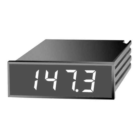
DP116
Thermocouple Miniature
Panel Thermometer
™
®
Advertisement
Table of Contents

Related Manuals for Omega DP116


Summary of Contents for Omega DP116
- Page 1 Where Do I Find Everything I Need for User’ s Guide Process Measurement and Control? OMEGA…Of Course! Shop on line at www.omega.com TEMPERATURE Thermocouple, RTD & Thermistor Probes, Connectors, Panels & Assemblies Wire: Thermocouple, RTD & Thermistor Calibrators & Ice Point References Recorders, Controllers &...
- Page 2 It is the policy of OMEGA to comply with all worldwide safety and EMC/EMI regulations that apply. OMEGA is constantly pursuing certification of its products to the European New Approach Directives. OMEGA will add the CE mark to every appropriate device upon certification.
- Page 3 T T A A B B L L E E O O F F C C O O N N T T E E N N T T S S S S E E C C T T I I O O N N P P A A G G E E Preface .
- Page 4 LEDs, and can be ordered with a green LED display as an option. The part numbers would then end with “-GR”. Example: DP116-JF1-GR Also, these thermocouple meters can be ordered with different power configurations. Refer to Table 1-3 for available choices.
- Page 5 MODEL TYPE °C or °F RESOLUTION COMMON MODE VOLTAGE (CMV) - the average of the DP116-JF1 1.0°F DP116-JF2 0.1°F voltage applied to both wires of a two wire or differential input. DP116-JC1 1.0°C DP116-JC2 0.1°C...
- Page 6 P P o o w w e e r r O O p p t t i i o o n n s s A A v v a a i i l l a a b b l l e e *-KC2 1.0°C -199.9 to +199.9°C 0.1°C MODEL POWER DP116-TC type 115 Vac ±15%, 50/60 Hz *-TF1 2.7°F -157 to +752°F 1.0°F *-TF2 1.8°F...
- Page 7 2.835 0.945 [24.00] [72.00] N N O O T T E E S S , , W W A A R R N N I I N N G G S S a a n n d d C C A A U U T T I I O O N N S S 0.197 Information that is especially important to note is identified by [5.00]...
- Page 8 DISPLAY Type:..................7-segment, LED Height: ..................0.56" (14.2 mm) Symbols:....................-1.8.8.8 Overrange Indication:........Three least-significant digits blank Colors: ..................Red - standard Green - optional DIGITAL INPUTS Hold:..............TTL or 5V CMOS compatible ENVIRONMENTAL Operating Temperature: ..........0° to 60°C(32° to 140°F) Storage Temperature: ..........-40° to 85°C (-40° to 185°F) Relative Humidity: ..........95% at 40°C (non-condensing) MECHANICAL DIMENSIONS Bezel: ...............0.94"...
- Page 9 S S E E C C T T I I O O N N 5 5 S S P P E E C C I I F F I I C C A A T T I I O O N N S S S S E E C C T T I I O O N N 1 1 I I N N T T R R O O D D U U C C T T I I O O N N INPUT TYPE: 1 1 .
- Page 10 1 1 . . 2 2 S S A A F F E E T T Y Y C C O O N N S S I I D D E E R R A A T T I I O O N N S S TABLE 4-2 (Cont’d) This device is marked with the international Caution symbol.
- Page 11 S S E E C C T T I I O O N N 2 2 A A B B O O U U T T T T H H E E M M E E T T E E R R TABLE 4-2 CALIBRATION VALUES 2 2 .
- Page 12 Connect the power to the meter. Refer to the 2 2 . . 2 2 B B a a c c k k o o f f t t h h e e M M e e t t e e r r appropriate model number in Table 4-2 for the proper Figure 2-2 illustrates the rear of the meter.
- Page 13 (Type J wire for Type J meter). To change the Factory preset jumpers, do the following steps: mV SOURCE T/C WIRE Disconnect the power from the unit before proceeding. OMEGA METER 1. Remove the main board from the case. Refer to Disassembly/Assembly Section 3.8. COPPER WIRE 2.
- Page 14 TABLE 4-1 (Cont’d) Voltage Jumper Pin Settings MODEL T/C CALIBRATOR METER POT TO AC VOLTAGE INSTALL REMOVE OPTION DISPLAY ADJUST DISPLAY 115 Vac W1, W3 230 Vac W1, W3 *-TF1 32°F 31°F † Zero 716°F 716°F Span *-TF2 32.0°F 32.0°F Zero Figure 3-1 shows the location of solder jumpers W1 through W3.
- Page 15 3 3 . . 2 2 C C o o n n v v e e r r t t i i n n g g ° ° F F t t o o ° ° C C ( ( v v i i c c e e v v e e r r s s a a ) ) TABLE 4-1 You must remove the printed circuit board from the case CALIBRATION VALUES WHEN USING...
- Page 16 Set the thermocouple calibrator to match the S S e e c c t t i i o o n n 3 3 . . 3 3 I I n n s s t t a a l l l l a a t t i i o o n n a a n n d d P P a a n n e e l l M M o o u u n n t t i i n n g g thermocouple type of your meter.
- Page 17 Connect the thermocouple calibrator output signal to the thermocouple input connector P3 as shown in 2.677 +0.028/-.000 [68.00 +0.70/-0.00] Figure 4-2. Connect the negative (red) thermocouple wire to connector P3, Pin 1. Connect the positive thermocouple wire to connector P3, Pin 2. Be sure to 0.874 +.012/-.000 R 0.06 [1.5] observe polarity and use the correct thermocouple...
- Page 18 " " + + " " L L E E A A D D W W I I R R E E " " - - " " L L E E A A D D W W I I R R E E source to an Omega MCJ Electronic Ice Point (or T T Y Y P P E E...
- Page 19 S S E E C C T T I I O O N N 4 4 O O P P E E R R A A T T I I O O N N A A N N D D C C A A L L I I B B R R A A T T I I O O N N 3 3 .
- Page 20 3 3 . . 5 5 A A n n a a l l o o g g O O u u t t p p u u t t C C o o n n n n e e c c t t i i o o n n s s The analog output is a linearized millivolt signal that is PULL TAB HERE equivalent to the displayed temperature.
- Page 21 3 3 . . 8 8 D D i i s s a a s s s s e e m m b b l l y y / / A A s s s s e e m m b b l l y y 3 3 .
- Page 22 3 3 . . 7 7 M M a a i i n n P P o o w w e e r r C C o o n n n n e e c c t t i i o o n n s s D D C C W W I I R R I I N N G G Connect the ac main power connections as shown below.