
Related Manuals for Omega DP26-RTD


Summary of Contents for Omega DP26-RTD
- Page 1 MADE IN User’ s Guide Shop on line at omega.com e-mail: info@omega.com For latest product manuals omegamanual.info DP26-RTD Differential Temperature Meter with RTD...
- Page 2 It is the policy of OMEGA to comply with all worldwide safety and EMC/EMI regulations that apply. OMEGA is constantly pursuing certification of its products to the European New Approach Directives. OMEGA will add the CE mark to every appropriate device upon certification.
- Page 3 PREFACE Manual Objectives This manual shows you how to set up and use the Differential RTD Meter. Standard Procedures: Checking voltage jumpers, or changing voltage power Mounting the panel Selecting the input type Selecting a decimal point position Selecting reading configuration (Fahrenheit or Celsius) Setting setpoint configuration Setting setpoint deadbands Entering temperature offset...
- Page 5 NOTES, WARNINGS and CAUTIONS Information that is especially important to note is identified by these labels: • NOTE • WARNING • CAUTION • IMPORTANT NOTE: provides you with information that is important to successfully setup and use the Programmable Digital Meter. CAUTION or WARNING: tells you about the risk of electric shock.
-
Page 6: Table Of Contents
Table of Contents Section Page 1. INTRODUCTION ..........1 1.1 UNPACKING . - Page 7 Section Page 4.8 SELECTING OUTPUT CONFIGURATION (OT.CF) ....26 4.8.1 Enabling or Disabling The Analog Output ....26 4.8.2 Selecting Analog Output as Current or Voltage .
- Page 8 List of Figures Figure Figure 2-1. Front-Panel ..........5 Figure 2-3.
-
Page 9: Introduction
SECTION 1. INTRODUCTION 1.1 UNPACKING Remove the Packing List and verify that all equipment has been received. If there are any questions about the shipment, use the phone numbers listed on the back cover to contact the Customer Service Department nearest you. Upon receipt of shipment, inspect the container and equipment for any signs of damage. -
Page 10: Safety Considerations
SECTION 1.2 SAFETY CONSIDERATIONS This device is marked with the international caution symbol. It is important to read this manual before installing or commissioning this device as it contains important information relating to Safety and EMC (Electromagnetic Compatibility). This instrument is a panel mount device protected in accordance with EN 61010-1:2001, electrical safety requirements for electrical equipment for measurement, control and laboratory. -
Page 11: About The Meter
SECTION 2. ABOUT THE METER 2.1 DESCRIPTION The Differential RTD meter is a value packed indicator/controller. Four full digits accurately display your temperature. Select from DIN (Alpha = .00385) or NIST (Alpha = .00392); 2,3, or 4 wire RTD. Your meter may be a basic indicator or it may include analog output or dual relay output. -
Page 12: Available Accessories
2.3 AVAILABLE ACCESSORIES Table 2.1 Accessories and Add-ons Add-On Options Special Calibration/Configuration SPC4 NEMA-4 Splash Proof Cover SPC18 NEMA-4 Splash Proof Cover, NEW Accessories TP1A Trimplate panel adaptor. Adapts DIN1A/DIN2A cases to larger panel cutouts RP18 19-In. Rack Panel for one (1) 1/8 DIN instrument RP28 19-In. -
Page 13: Front Of The Meter
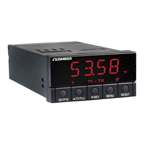
2.4 FRONT OF THE METER Figure 5-1 shows the location of each part of the front of the meter. •••• SETPTS T1/T2/ MENU RESET Figure 2-1 Front Panel Digital LED Display: -1.9.9.9. or 9.9.9.9. 4-digit, 14 segment, 13.8 mm (0.54") high LED display with programmable decimal point. These meter display windows light when appropriate: Setpoint 1 status Setpoint 2 status... - Page 14 2.4 FRONT OF THE METER (Continued) METER BUTTONS SETPTS Button In the run mode, press this button to sequentially recall the previous setpoint settings. After using the /T1/T2 /DEV buttons to alter these settings as desired, press the SETPTS button to store these new values. Unless you press the SETPTS, /T1/T2 /DEV button within 20 seconds to...
- Page 15 2.4 FRONT OF THE METER (Continued) MENU Button In the run mode, press the MENU button to terminate the current measuring process and enter you into the configuration mode. In the configuration mode, press the MENU button to store changes in the non-volatile memory and then advance you to the next menu item.
-
Page 16: Front-Panel Button Lock Out
2.5 FRONT PANEL LOCKOUT 2.5.1 PUSH BUTTON LOCKOUT To lock the RESET, MENU and SETPTS buttons, verify that the S3-A jumper is installed and the S3-E jumper is not installed, then follow these steps: In the run mode- Press and hold down the RESET button. The meter shows “SP.RS”. Do not release the RESET button. -
Page 17: Back Of The Meter
2.6 BACK OF THE METER Figure 2-2 shows the connector label mounted at the top of the meter housing. Table 2-2 gives a brief description of each connector at the back of the meter. POWER & INPUT CONNECTIONS (DIFFERENTIAL RTD) RTD2 RTD1 Figure 2-2 Connector label (ac Powered and dc Powered detail) -
Page 18: Table 2-2 Connector Description
2.6 BACK OF THE METER (Continued) Table 2-2 Connector Description Connector Description TB1-1 Setpoint 1: Normally open (N.O.1) connection TB1-2 Setpoint 1: Normally closed (N.C.1) connection TB1-3 Setpoint 1: Common (COM1) connection TB1-4 Setpoint 2: Normally open (N.O.2) connection TB1-5 Setpoint 2: Normally closed (N.C.2) connection TB1-6 Setpoint 2: Common (COM2) connection... -
Page 19: Disassembly
2.7 DISASSEMBLY You may need to open up the meter for one of the following reasons: • To check or change the 115 or 230 Vac power jumpers. • To install or remove jumpers on the main board. Disconnect the power supply before proceeding. To remove and access the main board, follow these steps: •... -
Page 20: Getting Started
SECTION 3. GETTING STARTED Caution: The meter has no power-on switch, so it will be in operation as soon you apply power. If you power off/on the meter, or perform a hard reset (press the RESET button twice), the meter shows "RST", followed by "D.RTD". 3.1 RATING/PRODUCT LABEL This label is located on top of the meter housing (Refer to Figure 3-3). -
Page 21: Figure 3.2 Main Board Jumper Positions
3.2 MAIN BOARD POWER JUMPERS (Continued) Figure 3-2 shows the main board jumpers. Figure 3.2 Main Board Jumper Positions Attach cable to P1. Figure 3.3 Upper Option Board Installation... -
Page 22: Table 3-1 S3 Jumper Functions
3.2 MAIN BOARD POWER JUMPERS (Continued) S2 jumpers are for sensor break indications: S2A jumper is not used S2B jumper is for positive sensor break on input 1 (i.e. heating) S2C jumper is for positive sensor break on input 2 (i.e. heating) S2D is not used S3 jumpers are used for the following (refer to Table 3-1): To enable or disable the front panel push-buttons... -
Page 23: Mounting The Meter
3.3 MOUNTING THE METER CONNECTOR LABEL PRODUCT CASE LABEL GASKET FRONT BEZEL Figure 3-3 Meter - Exploded View 1. Cut a hole in your panel, as shown in Figure 3-3. For PANEL THICKNESS specific dimensions refer to 6,4 (.25) MAX Figure 3-4. -
Page 24: Connecting Sensor Input
3.4 CONNECTING SENSOR INPUT Figure 3-5 through 3-7 illustrate how to connect you power sensors. Channel 2 +E1 +S1 -S1 -E1 Channel 1 Figure 3-5 2-Wire RTD Input Connection -S2 -E2 +E2 +S2 Channel 2 Channel 1 Figure 3-6 3-Wire RTD Input Connection -S2 -E2 +E2 +S2 Channel 2... -
Page 25: Connecting Main Power
3.5 CONNECTING MAIN POWER Connect the ac main power connections as shown in Figure 3-8. Warning: Do not connect AC power to your device until you have completed all input and output connections. This device must only be installed by a specially trained electrician with corresponding qualifications. Failure to follow all instructions and warnings may result in injury! Figure 3-8 Main Power Connections (ac powered unit) Table 3-2 shows the wire color and respective terminal connections for both USA and... -
Page 26: Figure 3-10. Main Power Connections - Dc Powered Unit
3.5 CONNECTING MAIN POWER (Continued) Connect the dc main power connections as shown in Figure 3-9.. Figure 3-9 Main Power Connections (dc powered unit) 3.6 ANALOG AND RELAY OUTPUT CONNECTIONS If you have purchased a meter with analog or dual relay or isolated analog output, refer to the following figures for output connections. -
Page 27: Figure 3-12. Analog Output Connections
3.6 ANALOG AND RELAY OUTPUT CONNECTIONS (continued) Figure 3-11 Analog Output Connections Figure 3-12 Isolated Analog Output Connections... -
Page 55: Table 10-1. Front Panel Displays
Table 10-1 Front-Panel Displays (continued) MENU /DEV /T1/T2/ DESCRIPTION P.BND Proportional Band Scroll right one digit Changes the value select from 0000 of the flashing digit through 9999 M.RST Manual Reset Scroll right one digit Changes the value of the flashing digit select from 0000 through 9999 T1.OF... -
Page 56: Setpoint Configuration Displays
SECTION 11. SETPOINT CONFIGURATION DISPLAYS Table 11-1 Setpoints Configuration Displays MENU /DEV /T1/T2/ DESCRIPTION SP 1 Press to scroll Press to change SETPOINT 1 Setpoint 1 to the next the value of the digitto the right flashing digit Select from -1999 through 9999 SP 2 Scroll right... -
Page 57: Specifications
SECTION 12. SPECIFICATIONS SIGNAL INPUT RTD types: DIN (0.00385) type 2,3, or 4 wire NIST (0.00392) type 2,3, or 4 wire Lead Resistance for Specified Accuracy: 2 Wire Up to 55 milliohm/lead 3 Wire Up to 10 ohms/lead balanced 4 Wire Up to 20 ohms/total unbalanced Isolation: Dielectric strength to 2500V transient per 3mm spacing based on EN 61010 for 260Vrms or dc... - Page 58 INPUT POWER INFORMATION: ~ AC units 115/230 V~(AC) ±10%, 50/60 Hz 7 W max, power consumption (Non-Isolated Analog Output) 8 W max, power consumption (Isolated Analog Output) DC units 10-32 Vdc 6 W max, power consumption (Non-Isolated Analog Output) 7 W max, power consumption (Isolated Analog Output) External Fuse Required: IEC 127-2/III Power...
- Page 59 ANALOG OUTPUT (if applicable) Signal type: Current or voltage Signal level: Current: 10 V max compliance at 20 mA output Voltage: 20 mA max for 0-10 V output Function: May be assigned to a display range or proportional control output with setpoint #1 when used as a control output.
-
Page 60: Figure 12-1 Meter Dimensions
48,0 (1.89) 96,0 (3.78) FRONT BEZEL 20,3 (.80) RETAINER CASE REAR COVER TOP VIEW SIDE VIEW PANEL THICKNESS 6,4 (.25) MAX 0,8 (.03) MIN R (.06) 45,00 + 0,61/-0,00 (1.772 + .024/–.000) 4 PLCS 92,00 + 0,81/–0,00 (3.622 + .032/–.000) NOTE: Dimensions in Millimeters (Inches) Figure 12-1 Meter Dimensions... -
Page 61: Factory Preset Values
SECTION 13. FACTORY PRESET VALUES Table 13-1 Factory Preset Values MENU ITEM FACTORY PRESET VALUES INPT Input Type: 385.3 (3 wire DIN RTD) DEC.P Decimal Point Position: FFF.F RD.CF Reading Configuration: R.1=F (Fahrenheit) S1.CF Setpoint 1 Configuration: S.1=A (Setpoint is active above) S.2=U (Setpoint is unlatched) S.3=0 (Setpoint 1 is assigned to T1-T2) S2.CF... -
Page 62: Ce Approvals
CE APPROVALS INFORMATION This product conforms to the EMC directive 89/336/EEC amended by 93/68/EEC, and with the European Low Voltage Directive 72/23/EEC. Electrical Safety EN61010-1:2001 Safety requirements for electrical equipment for measurement, control and laboratory. Double Insulation Pollution Degree 2 Dielectric withstand Test per 1 min •... - Page 63 WARRANTY/DISCLAIMER OMEGA ENGINEERING, INC. warrants this unit to be free of defects in materials and workmanship for a period of one (1) year from the date of purchase. In addition to OMEGA’s standard warranty period, OMEGA Engineering will extend the warranty period for four (4) additional years if the warranty card enclosed with each instrument is returned to OMEGA.
- Page 64 Where Do I Find Everything I Need for Process Measurement and Control? OMEGA…Of Course! Shop on line at www.omega.com TEMPERATURE Thermocouple, RTD & Thermistor Probes, Connectors, Panels & Assemblies Wire: Thermocouple, RTD & Thermistor Calibrators & Ice Point References Recorders, Controllers & Process Monitors...
Need help?
Do you have a question about the DP26-RTD and is the answer not in the manual?
Questions and answers