
Subscribe to Our Youtube Channel
Related Manuals for Omega DP116-RTD


Summary of Contents for Omega DP116-RTD
- Page 1 User’ s Guide MADE ® http://www.omega.com e-mail: info@omega.com DP116-RTD MINIATURE PANEL THERMOMETER...
- Page 2 CE mark to every appropriate device upon certification. The information contained in this document is believed to be correct but OMEGA Engineering, Inc. accepts no liability for any errors it contains, and reserves the right to alter specifications without notice.
-
Page 3: Table Of Contents
TABLE OF CONTENTS SECTION PAGE Preface ....... .ii Models Available ......iii Section Introduction . -
Page 4: Preface
PREFACE Manual Objectives: This manual shows you how to set up and use the RTD Panel Thermometer. This meter is an economical Miniature Temperature Panel Thermometer featuring a large display with a linearized analog output that is supplied as a standard feature. Each of the models* can be converted by the user to display in degrees Fahrenheit or Celsius between one degree and a tenth degree resolution. -
Page 5: Models Available
MODELS AVAILABLE TABLE 1-1 RTD MODELS AVAILABLE The following 3-1/2 digit mini RTD panel meters are available and discussed in this OperatorÕs Manual. MODEL TYPE ¡C or ¡F RESOLUTION DP116-MF1 1.0¡F DP116-MF2 0.1¡F DP116-MC1 1.0¡C DP116-MC2 0.1¡C Note The accuracies and ranges are listed in Section 5. TABLE 1-2 Power Options Available MODEL... - Page 6 TABLE 1-3 Other Models Available The following 3-1/2 digit mini thermocouple panel thermometers are discussed in a separate manual. MODEL TYPE ¡C or ¡F RESOLUTION DP116-JF1 1.0¡F DP116-JF2 0.1¡F DP116-JC1 1.0¡C DP116-JC2 0.1¡C DP116-KF1 1.0¡F DP116-KF2 0.1¡F DP116-KC1 1.0¡C DP116-KC2 0.1¡C DP116-TF1 1.0¡F...
- Page 7 NOTES, WARNINGS and CAUTIONS Information that is especially important to note is identified by these labels: NOTE: provides you with information that is important Note to successfully setup and use the Programmable Digital Meter. CAUTION or WARNING: tells you about the risk of electric shock.
- Page 8 NOTES...
-
Page 9: Introduction
SECTION 1 INTRODUCTION UNPACKING Remove the Packing List and verify that all equipment has been received. If there are any questions about the shipment, use the phone number for the Customer Service Department nearest you. Upon receipt of shipment, inspect the container and equipment for any signs of damage. -
Page 10: Safety Considerations
1.2 SAFETY CONSIDERATIONS This device is marked with the international caution symbol. It is important to read this manual before installing or commissioning this device as it contains important information relating to Safety and EMC (Electromagnetic Compatibility). Unpacking & Inspection Unpack the instrument and inspect for obvious shipping damage. -
Page 11: Section 2 About The Meter
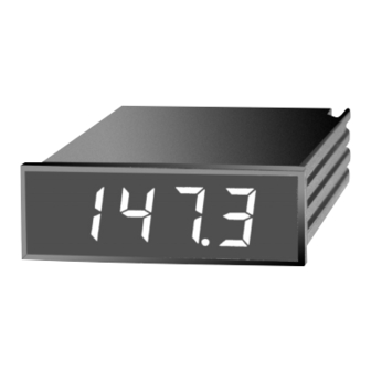
SECTION 2 ABOUT THE METER 2.1 Front of the Meter Figure 2-1 shows the panel thermometer. Figure 2-1. Panel Thermometer Features: Display:3 1/2 Digit, 7-Segment Red or Green LED Full-size:14.2 mm (0.56") LED Display Analog Output Standard 3/64 DIN Standard Panel Cutout Removable Screw-Clamp Cable Connector Display Hold Capability... -
Page 12: Back Of The Meter
Back of the Meter Figure 2-2 illustrates the rear of the meter. Figure 2-2. Rear View Showing P1, P2, P3 Locations 2.3 Connector Description Connector Description Connector PIN # (AC) Earth Ground (AC) Neutral (AC) Line (DC) -DC Return (DC) +DC (DC) No Connection (Not used) Display Hold (Active Low) Analog Return... -
Page 13: Section 3 Getting Started
SECTION 3 GETTING STARTED 3.1 Main Board Power Jumpers Caution: The meter has no power-on switch, so it will be in operation as soon you apply power. The meter can be configured to operate on 115VAC or 230VAC by the proper combination of the soldered wire jumpers that are located on the printed circuit board. - Page 14 Voltage Jumper Pin Settings AC VOLTAGE INSTALL REMOVE 115VAC W1, W3 230VAC W1, W3 Figure 3-1 shows the location of solder jumpers W1 through ZERO (COMPONENT SIDE) P2 2 TRANSFORMER SPAN Figure 3-1. Power Jumper Locations...
-
Page 15: Changing The Meter Parameters
3.2 Changing the Meter Parameters The proper combinations of jumper plugs S1, S2, S3, S4, and S5 inside the meter allow you to change various parameters of the meter. These parameters include resolution, range, units, RTD sensor configuration and sensor break configuration. You can change the parameters by moving the plugs on one or several of the jumper locations. - Page 16 The following tables summarizes what parameters you can change. TABLE 3-1 Range Parameters Option F/C Resolution Range *-MF1 ¡F 1¡ -328 to + 1562¡F *-MF2 ¡F 0.1¡ -199.9 to + 199.9¡F *-MC1 ¡C 1¡ -200 to + 850¡C *-MC2 ¡C 0.1¡...
- Page 17 Figure 3-3 gives an example of how to set S4 and S5 to configure a MF1 meter option. There is a jumper plug across A on S4 and another jumper plug across A on S5. B and C on S5 are not used. JUMPER PLUG JUMPER PLUG COVERING BOTH PINS...
-
Page 18: Installation And Panel Mounting
Section 3.3 Installation and Panel Mounting Figure 3-4 shows the panel cutout dimensions, the dimensions for the panel thickness, and the mounting clamp for mounting the unit in a panel. Connections will be done after mounting the unit. Remove the lens by inserting a paper clip or a small flat blade screwdriver into the rounded corner of the lens and lift out. - Page 19 2.677 +0.028/-.000 [68.00 +0.70/-0.00] 0.874 +.012/-.000 R 0.06 [1.5] [22.20 +0.30/-0.00] 4 PLCS MOUNTING SCREW HOLES PANEL THICKNESS 0.25 [6.4] MAX CLAMP 0.03 [0.8] MIN CLAMP PANEL CUTOUT SCREWS PANEL CUTOUT CASE MOUNTING CLAMP MOUNTING SCREW (2) LENS Figure 3-4. Installation Information...
-
Page 20: Sensor Input Connections
3.4 Sensor Input Connections The RTD sensor (see Figure 3-5), can be wired in three different ways. They are 2-, 3-, and 4-wire configurations. The meter is factory set internally to a 3-wire setup. If you wish to change it, refer to Table 3-2. 2-Wire RTD: Externally wire the P3 connector according to Figure 3-6. - Page 21 RED* (Signal Hi) Signal Hi METER BLACK* (Signal Lo) Signal Lo BLACK* (-Excitation) - Excitation Figure 3-8. 4-Wire RTD Wiring Note Refer to Table 3-1 and Table 3-2 for internal jumper settings. * Wire colors are for OMEGA RTD wiring only.
-
Page 22: Analog Output Connections
3.5 Analog Output Connections The analog output is a linearized millivolt signal that is equivalent to the displayed temperature. It comes as a standard feature with every unit. The resolution of the analog output is no greater than the resolution of the display. Note The analog output is a non-isolated signal. -
Page 23: Display Hold Connections
3.6 Display Hold Connections The ÒDisplay Hold" function can be used to freeze the display. Connect a single pole, single throw (SPST) switch between pins 1 and 2 on the P2 connector. The display will stop updating when this switch is on. When this switch is off, the display will update itself 2.5 times per second. -
Page 24: Main Power Connections
3.7 Main Power Connections Connect the ac main power connections as shown below. WARNING: Do not connect ac power to your meter until you have completed all input and output connections. Failure to do so may result in injury! This device must only be installed electrically by specially trained electrician with corresponding qualifications. - Page 25 DC WIRING The meter can be configured at the factory to operate on a 9Ð26 VDC non-isolated power. The DC voltage option is specified at the time of ordering. See Table 1-3 for model number listing. An AC powered meter cannot be converted to a DC powered meter or vice versa.
-
Page 26: Disassembly/Assembly
3.8 Disassembly/Assembly You must go through the following steps in order to Note remove the printed circuit board from the case if you want to change from 115VAC to 230VAC (or vice versa) or to change from Fahrenheit to Celsius (or vice versa). These changes must be performed by a qualified technician in order to avoid damage to the unit. - Page 27 PULL TAB HERE PC BOARD PUSH HERE Figure 3-13. Removing the PC Board from the Case When re-installing the printed circuit board: Hold the case (with the two mounting holes facing upwards and to the right side of the case) in the left hand. Hold the printed circuit board with the components showing (soldered side down) in the right hand.
-
Page 28: Section 4 Operation And Calibration
SECTION 4 OPERATION AND CALIBRATION Important: These changes must be performed by a qualified technician. WARNING: Do not connect ac power to your meter until you have completed all input and output connections. Failure to do so may result in injury! Wire the meter according to the wiring section. -
Page 29: Calibration Procedure
4.2 CALIBRATION PROCEDURE Remove the front lens. Connect power to the meter, observing proper wiring procedures. Connect the precision resistance source to the P3 connector observing proper wiring configuration. For 3Ðwire connections, use pins 1, 2, 3, and 4. Refer to Figures 4-1 through 4-3. - Page 30 + Excitation PRECISION Signal Hi RESISTANCE BLACK Signal Lo SOURCE BLACK BLACK - Excitation Figure 4-3. 4-Wire Configuration TABLE 4-1 CALIBRATION VALUES WHEN YOU ARE USING RESISTANCE SOURCE MODEL RESISTANCE METER POT TO OPTION READING DISPLAY ADJUST *-MF1 93.01 00¡F ZERO 375.51 1472¡F...
-
Page 31: Specifications
SECTION 5 SPECIFICATIONS INPUT TYPE: RTD:............100-ohm platinum with alpha of 0.00385 Calibration:................IEC 751 (IPTS-68) Configuration:...........2-, 3-, or 4-wire RTD connection Polarity: ....................Bipolar Zero: ................Adjustable ±20¡C (±36¡F) Zero Tempco : ..............±0/05 degree/degree Sensor-wire Resistance Tempco Effect per Conductor: 2-wire: ............20 mdeg/½/degree, up to 3.8 ½ 3-wire: ............50µdeg/½/degree, up to 100 ½... - Page 32 DISPLAY Type:..................7-segment, LED Height: ..................0.56" (14.2 mm) Symbols:....................-1.8.8.8 Overrange Indication:........Three least-significant digits blank Colors: ..................Red - standard Green - optional DIGITAL INPUTS Hold:..............TTL or 5V CMOS compatible ENVIRONMENTAL Operating Temperature: ..........0¡ to 60¡C(32¡ to 140¡F) Storage Temperature: ..........-40¡ to 85¡C (-40¡ to 185¡F) Relative Humidity: ..........95% at 40¡C (non-condensing) MECHANICAL DIMENSIONS Bezel: ...............0.94"...
- Page 33 0.945 [24.00] 2.835 [72.00] 0.197 [5.00] 4.134 [105.00] 4.60 [116.8] 2.661 0.858 [21.80] [67.60] SIDE VIEW TOP VIEW 2.677 +0.028/-.000 [68.00 +0.70/-0.00] 0.874 +.012/-.000 R 0.06 [1.5] [22.20 +0.30/-0.00] 4 PLCS PANEL THICKNESS 0.25 [6.4] MAX 0.03 [0.8] MIN PANEL CUTOUT Figure 5-1 Dimensions...
-
Page 34: Section 6 Glossary
SECTION 6 GLOSSARY COMMON MODE REJECTION (CMR) - a measure of the affect of a voltage on the indicated display. It is the ratio of the common mode voltage to the measured voltage due to a common mode voltage. COMMON MODE VOLTAGE (CMV) - the average of the voltage applied to both wires of a two wire or differential input. - Page 35 Department will issue an Authorized Return (AR) number immediately upon phone or written request. Upon examination by OMEGA, if the unit is found to be defective it will be repaired or replaced at no charge. OMEGAÕs WARRANTY does not apply to defects resulting from any action of the purchaser, including but not limited to mishandling, improper interfacing, operation outside of design limits, improper repair, or unauthorized modification.
- Page 36 Where Do I Find Everything I Need for Process Measurement and Control? OMEGAÉOf Course! TEMPERATURE Thermocouple, RTD & Thermistor Probes, Connectors, Panels & Assemblies Wire: Thermocouple, RTD & Thermistor Calibrators & Ice Point References Recorders, Controllers & Process Monitors Infrared Pyrometers PRESSURE, STRAIN AND FORCE Transducers &...
Need help?
Do you have a question about the DP116-RTD and is the answer not in the manual?
Questions and answers