
Related Manuals for DFI HM960-QM87


Summary of Contents for DFI HM960-QM87
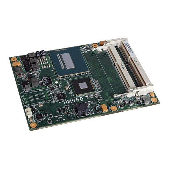
- Page 1 HM960-QM87/HM86 COM Express Basic Module User’s Manual A26810447 Chapter 1 Introduction www.dfi .com...
-
Page 2: Copyright
Copyright FCC and DOC Statement on Class B This publication contains information that is protected by copyright. No part of it may be re- This equipment has been tested and found to comply with the limits for a Class B digital produced in any form or by any means or used to make any transformation/adaptation without device, pursuant to Part 15 of the FCC rules. -
Page 3: Table Of Contents
About the Package RAID Levels .................75 ..................5 Settings ..................75 Chapter 1 - Introduction ................6 Chapter 8 - Intel AMT Settings (HM960-QM87) ......78 Specifications ....................6 Overview ....................... Features ......................7 Enable Intel AMT in the AMI BIOS ............ -
Page 4: About This Manual
About this Manual Static Electricity Precautions An electronic file of this manual is included in the CD. To view the user’s manual in the CD, in- It is quite easy to inadvertently damage your PC, system board, components or devices even sert the CD into a CD-ROM drive. -
Page 5: About The Package
About the Package The package contains the following items. If any of these items are missing or damaged, please contact your dealer or sales representative for assistance. • One HM960 board • • One QR (Quick Reference) Optional Items • COM331-B carrier board kit •... -
Page 6: Chapter 1 - Introduction
• Supports High Defi nition Audio interface Damage Free • Monitors CPU temperature and overheat alarm • Intel ® I217LM with iAMT9.0 Gigabit Ethernet Phy (HM960-QM87) Intelligence • Monitors CPU fan speed and failure alarm • Intel ® I217LM Gigabit Ethernet Phy (HM960-HM86) •... -
Page 7: Features
Chapter 1 Features • Dimensions ® - COM Express Basic - 95mm (3.74") x 125mm (4.9") • Compliance - PICMG COM Express R2.1, Type 6 ® • Watchdog Timer The Watchdog Timer function allows your application to regularly “clear” the system at the set Note: time interval. -
Page 8: Chapter 2 - Concept
Chapter 2 - Concept COM Express Module Standards The figure below shows the dimensions of the different types of COM Express modules. HM960-QM87/HM86 is a COM Express Basic module. The dimension is 95mm x 125mm. Common for all Form Factors Extended only... -
Page 9: Specification Comparison Table
Chapter 2 Specification Comparison Table The table below shows the COM Express standard specifications and the corresponding specifications supported on the HM960-QM87/HM86 module. COM Express Module Base DFI HM960-QM87/HM86 COM Express Module Base DFI HM960-QM87/HM86 Specification Type 6 Type 6... -
Page 10: Chapter 3 - Hardware Installation
Chapter 3 Chapter 3 - Hardware Installation Block Diagram Board Layout For HM960-QM87 Intel Processor LVDS Port 3460 CORE CORE CORE CORE VR12.5 (Vcore) 4th Generation; Channel A 1333/1600MHz Intel Core i7/i5/i3 ® ™ DDR3L BGA 1364 SODIMM i3/i5/i7 PEG 16x LANES... - Page 11 Chapter 3 For HM960-HM86 Processor LVDS Ports 3460 CORE CORE CORE CORE VR12.5 4th Generation; Channel A (Vcore) 1333/1600MHz Intel Core i7/i5/i3 ® ™ DDR3L SODIMM PEG 16x LANES PEG 16x LANES Memory Graphics Channel B CORE Controller 1333/1600MHz DDR3L SODIMM DMI x4 Intel...
-
Page 12: Mechanical Diagram
Chapter 3 Mechanical Diagram HM960-QM87/HM86 Module with Heat Sink HM960-QM87/HM86 Module 53.00 0.00 4.08 4.08 12.84 Top View 45.61 79.64 Heat sink and fan 91.08 91.08 95.15 Heat spreader Module PCB standoff Side View of the Module with Heat Sink and Carrier Board Bottom View 14.00... -
Page 13: System Memory
Chapter 3 Installing the DIMM Module Important: Electrostatic discharge (ESD) can damage your board, processor, disk drives, add-in boards, and other components. Perform installation procedures at an ESD workstation Note: only. If such a station is not available, you can provide some ESD protection by wear- The system board used in the following illustrations may not resemble the actual one. -
Page 14: Connectors
Chapter 3 Connectors 5. Grasping the module by its edges, align the module into the socket at an approximately 30 degrees angle. Apply firm even pressure to each end of the module until it slips down into the socket. The contact fingers on the edge of the module will almost completely disappear CPU Fan Connector inside the socket. -
Page 15: Com Express Connectors
Connect the COM Express connectors (located on the solder side of the board) to the COM Express connectors on the carrier board. Refer to the “Installing HM960-QM87/HM86 onto a Carrier Board” section for more information. COM Express Connectors Refer to the following pages for the pin functions of these connectors. - Page 16 Chapter 3 COM Express Connectors Row A Row B Row A Row B GND (FIXED) GND (FIXED) GND (FIXED) GND (FIXED) PCIE_TX5+ PCIE_RX5+ GBE0_MDI3- GBE0_ACT# PCIE_TX5- PCIE_RX5- GBE0_MDI3+ LPC_FRAME# GPI0 GPO1 GBE0_LINK100# LPC_AD0 PCIE_TX4+ PCIE_RX4+ GBE0_LINK1000# LPC_AD1 PCIE_TX4- PCIE_RX4- GPO2 GBE0_MDI2- LPC_AD2 PCIE_TX3+...
- Page 17 Chapter 3 Row C Row D Row C Row D GND (FIXED) GND (FIXED) GND (FIXED) GND (FIXED) PEG_RX0+ PEG_TX0+ PEG_RX0- PEG_TX0- USB_SSRX0- USB_SSTX0- TYPE0# PEG_LANE_RV# USB_SSRX0+ USB_SSTX0+ PEG_RX1+ PEG_TX1+ PEG_RX1- PEG_TX1- TYPE1# TYPE2# USB_SSRX1- USB_SSTX1- PEG_RX2+ PEG_TX2+ USB_SSRX1+ USB_SSTX1+ PEG_RX2- PEG_TX2- GND (FIXED)
-
Page 18: Com Express Connectors Signal Discription
I/O Bi-directional input / output signal OD Open drain output AC97/HDA Signals Descriptions Signal Pin# Pin Type Pwr Rail /Tolerance HM960-QM87/HM86 Carrier Board Description AC/HAD_RST# O CMOS 3.3V Suspend/3.3V Connect to CODEC pin 11 RESET# Reset output to CODEC, active low. - Page 19 Chapter 3 PCI Express Lanes Signals Descriptions Signal Pin# Pin Type Pwr Rail /Tolerance HM960-QM87/HM86 Carrier Board Description PCIE_TX0+ AC Coupling capacitor O PCIE AC coupled on Module Connect to PCIE device or slot PCI Express Differential Transmit Pairs 0...
- Page 20 Chapter 3 PEG Signals Descriptions Signal Pin# Pin Type Pwr Rail /Tolerance HM960-QM87/HM86 Carrier Board Description PEG_TX6+ AC Coupling capacitor O PCIE AC coupled on Module Connect to PCIE device or slot PCI Express Graphics transmit differential pairs 6 PEG_TX6-...
- Page 21 Chapter 3 DDI Signals Descriptions Signal Pin# Pin Type Pwr Rail /Tolerance HM960-QM87/HM86 Carrier Board Description DDI1_PAIR0+/SDVO1_RED+ Connect AC Coupling Capacitors 0.1uF to Device O PCIE AC coupled off Module DDI 1 Pair 0 differential pairs/Serial Digital Video B red output differential pair DDI1_PAIR0-/SDVO1_RED- Connect AC Coupling Capacitors 0.1uF to Device...
- Page 22 USB7- and ESD suppressors to GND to USB connector Module designer's discretion.(HM960-QM87/HM86 default set as a host) USB over-current sense, USB channels 0 and 1. A pull-up for this line shall be present on the Module. An open drain driver from a USB...
- Page 23 Chapter 3 LVDS Signals Descriptions Signal Pin# Pin Type Pwr Rail /Tolerance HM960-QM87/HM86 Carrier Board Description LVDS_A0+ Connect to LVDS connector O LVDS LVDS LVDS_A0- LVDS_A1+ Connect to LVDS connector O LVDS LVDS LVDS_A1- LVDS Channel A differential pairs LVDS_A2+...
- Page 24 Chapter 3 VGA Signals Descriptions Signal Pin# Pin Type Pwr Rail /Tolerance HM960-QM87/HM86 Carrier Board Description VGA_RED O Analog Analog PD 150 TO GND PD 150R,connect to VGA connector with EMI Red for monitor. Analog output VGA_GRN O Analog Analog...
- Page 25 Chapter 3 Power and System Management Signals Descriptions Signal Pin# Pin Type Pwr Rail /Tolerance HM960-QM87/HM86 Carrier Board Description SUS_STAT# O CMOS 3.3V Suspend/3.3V Indicates imminent suspend operation; used to notify LPC devices. Indicates system is in Suspend to RAM state. Active low output. An...
- Page 26 Chapter 3 Power and GND Signal Descriptions Signal Pin# Pin Type Pwr Rail /Tolerance HM960-QM87/HM86 Carrier Board Description A104~A109 B104~B109 VCC_12V Power Primary power input: +12V nominal. All available VCC_12V pins on the connector(s) shall be used. C104~C109 D104~D109 Standby power input: +5.0V nominal. If VCC5_SBY is used, all available VCC_5V_SBY pins on the connector(s) shall be used.
-
Page 27: Standby Power Led
Bottom View of the Heat Sink • “1” and “2” denote the locations of the thermal pads designed to contact the corresponding compo- nents that are on HM960-QM87/HM86. Important: Remove the plastic covering from the thermal pads prior to mounting the heat sink onto HM960-QM87/HM86. -
Page 28: Installing Hm960-Qm87/Hm86 Onto A Carrier Board
The carrier board (COM331-B) used in this section is for reference purpose only and may not resemble your carrier board. These illustrations are mainly to guide you on how to install HM960-QM87/HM86 onto the carrier board of your choice. Mounting hole •... - Page 29 Bolts Bolts 7. Position the heat sink on the top of HM960-QM87/HM86 with the heat sink’s mounting holes aligned with HM960-QM87/HM86 mounting holes. Insert one of the provided long 5. The photo below shows the solder side of the board with the screws already fixed in place.
- Page 30 The photo below shows the locations of the long/short mounting screws. 9. Grasping HM960-QM87/HM86 by its edges, position it on top of the carrier board with its mounting holes aligned with the bolts on the carrier board. This will also align the COM Express connectors of the two boards to each other.
-
Page 31: Installing The Com Express Debug Card
Chapter 3 Installing the COM Express Debug Card 2. Connect the COMe-DEBUG card to COMe-LINK1 via a cable. COMe-DEBUG Note: The system board used in the following illustrations may not resemble the actual board. These illustrations are for reference only. Code Review 80 Port Display Control... - Page 32 Chapter 3 3. Fasten bolts with mounting screws through mounting holes to be fixed in place. 5. Align the mounting hole on the heat sink with the mounting hole on the module and secure the heat sink onto the module by a mounting screw from the bottom side of the module.
- Page 33 Chapter 3 6. Grasp HM960-QM87/HM86 with the heat sink by its edges and position them down firmly on the top of the COMe-LINK1 debug card. Cable COM Express Module COMe-LINK1 Carrier Board Side View of the Module, Debug Card and Carrier Board COMe-DEBUG 7.
-
Page 34: Chapter 4 - Bios Setup
Chapter 4 Chapter 4 - BIOS Setup Legends Overview KEYs Function The BIOS is a program that takes care of the basic level of communication between the CPU and peripherals. It contains codes for various advanced features found in this system board. Right and Left Arrows Moves the highlight left or right to select a The BIOS allows you to configure the system and save the configuration in a battery-backed... -
Page 35: Ami Bios Setup Utility
Chapter 4 AMI BIOS Setup Utility Advanced The Advanced menu allows you to configure your system for basic operation. Some entries are Main defaults required by the system board, while others, if enabled, will improve the performance of your system or let you set some features according to your preference. The Main menu is the first screen that you will see when you enter the BIOS Setup Utility. - Page 36 Chapter 4 ACPI Settings Trusted Computing This section is used to configure the ACPI settings. This section configures settings relevant to Trusted Computing innovations. Aptio Setup Utility - Copyright (C) 2012 American Megatrends, Inc. Aptio Setup Utility - Copyright (C) 2012 American Megatrends, Inc. Advanced Advanced Confi...
- Page 37 Chapter 4 PC Health Status CPU Configuration This section displays hardware health monitor. This section is used to configure the CPU. It will also display the detection of CPU information. Aptio Setup Utility - Copyright (C) 2012 American Megatrends, Inc. Aptio Setup Utility - Copyright (C) 2012 American Megatrends, Inc.
- Page 38 Chapter 4 Turbo Mode SATA Configuration If you want the system to run at a faster speed, set this field to Enabled. However, This section is used to configure the settings of SATA device. compatibility problems may occur with some DRAMs if the system is running in Turbo mode.
- Page 39 Chapter 4 When AHCI mode is selected in the SATA Mode Selection, it will display the following Smart Response Technology information: This field is used to enable or disable the Smart Response Technology. Aptio Setup Utility - Copyright (C) 2012 American Megatrends, Inc. Port 0/1/2/4/5 Advanced SATA Controller(s)
- Page 40 Chapter 4 Intel(R) Rapid Start Technology AMT Configuration This section is used to enable or disable the Intel Rapid Start Technology. This section configures the parameters of Active Management Technology. Aptio Setup Utility - Copyright (C) 2012 American Megatrends, Inc. Aptio Setup Utility - Copyright (C) 2012 American Megatrends, Inc.
- Page 41 Chapter 4 USB Configuration Device reset time-out This section is used to configure the parameters of USB. Select the USB mass storage device start unit command timeout. Device power-up delay Aptio Setup Utility - Copyright (C) 2012 American Megatrends, Inc. Advanced Maximum time the device will take before it properly reports itself to the Host Controller.
- Page 42 Chapter 4 Network Stack PCH-FW Configuration This section is used to enable or disable UEFI network stack. This section is used to configure the parameters of Management Engine Technology. Aptio Setup Utility - Copyright (C) 2012 American Megatrends, Inc. Aptio Setup Utility - Copyright (C) 2012 American Megatrends, Inc. Advanced Advanced Network Stack...
- Page 43 General Help Previous Values Optimized Defaults Save and Reset ESC: Exit Version 2.15.1236. Copyright (C) 2012 American Megatrends, Inc. WatchDog1 function For HM960-QM87/HM86 module board (Reset HM960-QM87/HM86 by hardware). WatchDog2 function For carrier board usage. Chapter 4 BIOS Setup www.dfi .com...
-
Page 44: Chipset
Chapter 4 Chipset Intel(R) Ethernet Network Connection i217-LM - 88:88:88:... This section is used to configure the parameters of Gigabit Ethernet device. The section configures the relevant functions of chipset. Aptio Setup Utility - Copyright (C) 2012 American Megatrends, Inc. Aptio Setup Utility - Copyright (C) 2012 American Megatrends, Inc. - Page 45 Chapter 4 PCH-IO Configuration PCI Express Configuration This section configures PCH parameters. Aptio Setup Utility - Copyright (C) 2012 American Megatrends, Inc. Chipset Aptio Setup Utility - Copyright (C) 2012 American Megatrends, Inc. PCI Express Confi guration PCI Express Root Port 1 Chipset Settings.
- Page 46 Chapter 4 PME SCI USB Configuration Enable or disable PCI Express PME SCI. Aptio Setup Utility - Copyright (C) 2012 American Megatrends, Inc. Chipset Hot Plug USB Confi guration Mode of operation of Enable or disable PCI Express Hot Plug. XHCI Controller.
- Page 47 Chapter 4 System Agent (SA) Configuration PCH Azalia Configuration This section configures System Agent (SA) parameters. Aptio Setup Utility - Copyright (C) 2012 American Megatrends, Inc. Chipset Aptio Setup Utility - Copyright (C) 2012 American Megatrends, Inc. PCH Azalia Confi guration Control detection of the Chipset Azalia device.
- Page 48 Chapter 4 Graphics Configuration DVMT Pre-Allocated Select DVMT 5.0 Pre-Allocated (Fixed) Graphics Memory size used by the Internal Aptio Setup Utility - Copyright (C) 2012 American Megatrends, Inc. Graphics Device. Please refer to the screen shown below. Chipset Graphics Confi guration Select which of IGFX/ Aptio Setup Utility - Copyright (C) 2012 American Megatrends, Inc.
- Page 49 Chapter 4 NB PCIe Configuration Secondary IGFX Boot Display This section is used to configure the settings of NB PCI Express. Select secondary display device. LCD Panel Type Aptio Setup Utility - Copyright (C) 2012 American Megatrends, Inc. Chipset Select LCD panel used by Internal Graphics Device by selecting the appropriate setup item.
- Page 50 Chapter 4 NB PCIe Bifurcation Configuration Memory Configuration This field is used to configure the parameters of CPU PEG Bifurcation. This section only display the parameters of memory configuration. Aptio Setup Utility - Copyright (C) 2012 American Megatrends, Inc. Aptio Setup Utility - Copyright (C) 2012 American Megatrends, Inc. Chipset Chipset Memory Information...
-
Page 51: Boot
Chapter 4 Boot CSM Parameters Aptio Setup Utility - Copyright (C) 2012 American Megatrends, Inc. Aptio Setup Utility - Copyright (C) 2012 American Megatrends, Inc. Main Advanced Chipset Boot Security Save & Exit Main Advanced Chipset Boot Security Save & Exit Launch PXE OpROM policy Boot Confi... -
Page 52: Security
Chapter 4 Security Save & Exit Aptio Setup Utility - Copyright (C) 2012 American Megatrends, Inc. Aptio Setup Utility - Copyright (C) 2012 American Megatrends, Inc. Main Advanced Chipset Boot Security Save & Exit Main Advanced Chipset Boot Security Save & Exit Save Changes and Reset Reset the system after Password Description... -
Page 53: Updating The Bios
Chapter 4 Updating the BIOS Notice: BIOS SPI ROM To update the BIOS, you will need the new BIOS file and a flash utility, AFUDOS.EXE. 1. The Intel Management Engine has already been integrated into this system board. Due to ®... -
Page 54: Chapter 5 - Supported Software
Chapter 5 Chapter 5 - Supported Software Auto Run Page (For Windows 7) The CD that came with the system board contains drivers, utilities and software applications required to enhance the performance of the system board. Insert the CD into a CD-ROM drive. The autorun screen (Mainboard Utility CD) will appear. If after inserting the CD, “Autorun”... - Page 55 Chapter 5 Auto Run Page (For Windows XP) Microsoft Framework 3.5 (For Windows XP) Note: Before installing Microsoft .NET Framework 3.5, make sure you have updated your Windows XP operating system to Service Pack 3. To install the driver, click “Microsoft .NET Framework 3.5” on the main menu. 1.
-
Page 56: Intel Chipset Software Installation Utility
Chapter 5 Intel Chipset Software Installation Utility 3. Click Exit. The Intel Chipset Software Installation Utility is used for updating Windows INF files so that the Intel chipset can be recognized and configured properly in the system. To install the utility, click “Intel Chipset Software Installation Utility” on the main menu. 1. - Page 57 Chapter 5 Microsoft DirectX 9.0C (For Windows XP) 3. Go through the readme document for system require- ments and installation tips then To install the utility, click “Microsoft DirectX 9.0C Driver” on the main menu. click Next. 1. Click “I accept the agreement”...
- Page 58 Chapter 5 Intel HD Graphics Drivers (For Windows XP) 3. Go through the readme document for more installation tips then click Next. Note: Before installing Intel HD Graphics Drivers, make sure you have installed Microsoft .NET Framework 3.5 SP1. To install the driver, click “Intel HD Graphics Drivers” on the main menu. 1.
- Page 59 Chapter 5 Intel HD Graphics Drivers (For Windows 7/8) 3. Go through the readme docu- ment for system requirements and installation tips then click To install the driver, click “Intel HD Graphics Drivers” on the main menu. Next. 1. Setup is now ready to install the graphics driver.
-
Page 60: Intel Management Engine Drivers
Chapter 5 Intel Management Engine Drivers 3. Setup is currently installing the driver. After installation has com- pleted, click Next. To install the driver, click “Intel Management Engine Drivers” on the main menu. 1. Setup is ready to install the driver. Click Next. - Page 61 To install the driver, click “Audio Drivers (for COM331-B Carrier Board” on the main menu The LAN drivers for Windows XP supporting on the HM960-QM87/HM86 system board has to be installed manually. When you want to install the LAN driver for Windows XP, please follow the steps below to accomplish the installation.
- Page 62 Chapter 5 3. Choose the option "Don't 6. Insert the installation disk search. I will choose the and make sure the selected driver to install" in order to drive is correct. select the device driver from a list, and click "Next." (For 32-bit, the fi...
- Page 63 Chapter 5 Intel LAN Drivers (For Windows 7/8) 9. Click "Finish" to close the wizard. To install the driver, click “Intel LAN Drivers” on the main menu. 1. Setup is ready to install the driver. Click Next. 10. After completing the instal- lation, the Network adapters "Intel(R) Ethernet Connection 2.
- Page 64 DFI Utility 4. Click Install to begin the installation. DFI Utility provides information about the board, HW Health, Watchdog and DIO. To access the utility, click “DFI Utility” on the main menu. 1. Setup is ready to install the DFI Utility drifer.
- Page 65 Chapter 5 The DFI Utility icon will appear on the desktop. Double-click the icon to open the utility. 3. Enter “User Name” and “Organi- zation” information and then click Next 4. Click Install to begin the installation. Information 5. After completing installation, click Finish.
- Page 66 Chapter 5 WatchDog Backlight Chapter 5 Supported Software www.dfi .com...
- Page 67 Chapter 5 Intel USB 3.0 Drivers (For Windows 7 only) 3. Go through the readme docu- ment for more installation tips then click Next. To install the driver, click “Intel USB 3.0 Driver” on the main menu. 1. Setup is ready to install the driver. Click Next.
- Page 68 Chapter 5 Intel Rapid Storage Technology 3. Read the license agreement then click Yes. The Intel Rapid Storage Technology is a utility that allows you to monitor the current status of the SATA drives. It enables enhanced performance and power management for the storage subsystem.
- Page 69 Chapter 5 F6 Floppy 6. Click “Yes, I want to restart my computer now” then click Finish. This is used to create a floppy driver diskette needed when you install Windows® XP using Restarting the system will allow the the F6 installation method. This will allow you to install the operating system onto a hard drive new software installation to take when in AHCI mode.
- Page 70 Chapter 5 Intel Turbo Boost Monitor (For Windows 7/8) 4. Click Install. To install the driver, click “Intel Turbo Boost Monitor” on the main menu. 1. The setup program is configuring the new software installation 5. The setup program is currently installing the software.
- Page 71 Chapter 5 Intel Rapid Start Technology (For Windows 7/8) Infineon TPM Drivers and Tools (option) The Intel Rapid Start Technology is a utility that allows your system to wake up and run faster. To install the driver, click “Infineon TPM driver and tool (option)” on the main menu. To install the driver, click “Intel Rapid Start Technology”...
- Page 72 Chapter 5 4. Enter the necessary information 7. TPM requires installing the Micro- and then click Next. soft Visual C++ package prior to installing the utility. Click Install. 5. Select a setup type and then click 8. The setup program is currently Next.
- Page 73 Chapter 5 Adobe Acrobat Reader 9.3 10. Click “Yes“ to restart your system. To install the reader, click “Adobe Acrobat Reader 9.3” on the main menu. 1. Click Next to install or click Change Destination Folder to select another folder. 2.
-
Page 74: Chapter 6 - Gpio Programming Guide
Chapter 6 Chapter 6 - GPIO Programming Guide Function Description Get_EC_Data (unsigned char ucData): Read a Byte data from EC. Write_EC_Data (unsigned char ucData, unsigned char Data): Write a Byte data to EC. Sample Code GPIO Input Process EC_DIO_Read_Input() BYTE Data; //Pin0-3 Input Mode Data = Get_EC_Data(0xBA);... -
Page 75: Chapter 7 - Raid (Hm960-Qm87)
Chapter 7 Chapter 7 - RAID (HM960-QM87) Settings The system board allows configuring RAID on Serial ATA drives. It supports RAID 0, RAID 1, To enable the RAID function, the following settings are required. RAID 5 and RAID 10. 1. Connect the Serial ATA drives. - Page 76 Windows setup has copied these files again, remove the floppy diskette so that Windows setup can reboot as needed. 4. Read the license agree- ment and click “I accept the terms in the License Agreement.“ Then, click Next. Chapter 7 RAID (HM960-QM87) www.dfi .com...
- Page 77 Finish. Next. 6. Click Next to install to the default folder or click change to choose another destination folder. 7. Confirm the installation and click Next. Chapter 7 RAID (HM960-QM87) www.dfi .com...
-
Page 78: Chapter 8 - Intel Amt Settings (Hm960-Qm87)
Chapter 8 Chapter 8 - Intel AMT Settings (HM960-QM87) Enable Intel AMT in the AMI BIOS ® Overview 1. Power-on the system then press <Del> to enter the main menu of the AMI BIOS. Intel Active Management Technology (Intel AMT) combines hardware and software solution to ®... -
Page 79: Extension (Mebx) Screen
Copyright(C) 2003-12 Intel Corporation. All Rights Reserved. MAIN MENU MEBx Login > Intel (R) ME General Settings > Intel (R) AMT Confi guration MEBx Exit Intel(R) ME Password [] = Move Highlight [Enter] = Select Entry [Esc]= Exit Chapter 8 Intel AMT Settings (HM960-QM87) www.dfi .com... - Page 80 Copyright(C) 2003-12 Intel Corporation. All Rights Reserved. MAIN MENU > Intel (R) ME General Settings > Intel (R) AMT Confi guration MEBx Exit [] = Move Highlight [Enter] = Select Entry [Esc]= Exit Chapter 8 Intel AMT Settings (HM960-QM87) www.dfi .com...
- Page 81 <Anytime> > Network Setup Activate Netwok Access Unconfi gure Network Access <Full Unprovision> > Remote Setup And Confi guration > Power Control [] = Move Highlight [Enter] = Select Entry [Esc]= Exit Chapter 8 Intel AMT Settings (HM960-QM87) www.dfi .com...
- Page 82 Legacy Redirection Mode <Disabled> Disabled Enabled Menu for FW Redirection Confi guration [] = Move Highlight [Enter] = Select Entry [Esc]= Exit [] = Move Highlight [Enter] = Complete Entry [Esc]= Discard Changes Chapter 8 Intel AMT Settings (HM960-QM87) www.dfi .com...
- Page 83 Legacy Redirection Mode <Disabled> Legacy Redirection Mode <Disabled> Disabled Disabled Enabled Enabled [] = Move Highlight [Enter] = Complete Entry [Esc]= Discard Changes [] = Move Highlight [Enter] = Complete Entry [Esc]= Discard Changes Chapter 8 Intel AMT Settings (HM960-QM87) www.dfi .com...
- Page 84 > Power Control Default Password Only During Step And Confi guration Anytime [] = Move Highlight [Enter] = Complete Entry [Esc]= Discard Changes [] = Move Highlight [Enter] = Complete Entry [Esc]= Discard Changes Chapter 8 Intel AMT Settings (HM960-QM87) www.dfi .com...
- Page 85 > TCP/ IP Settings Shared/ Dedicated FQDN <Shared> Dynamic DNS Update <Disabled> Computer Domain Name [Enter] = Complete Entry [Esc]= Discard Changes [] = Move Highlight [Enter] = Select Entry [Esc]= Exit Chapter 8 Intel AMT Settings (HM960-QM87) www.dfi .com...
- Page 86 Shared/ Dedicated FQDN <Shared> Dynamic DNS Update <Disabled> Disabled Enabled Disabled Enabled [] = Move Highlight [Enter] = Complete Entry [Esc]= Discard Changes [] = Move Highlight [Enter] = Complete Entry [Esc]= Discard Changes Chapter 8 Intel AMT Settings (HM960-QM87) www.dfi .com...
- Page 87 > Remote Setup And Confi guration > Power Control Full Unprovision [] = Move Highlight [Enter] = Complete Entry [Esc]= Discard Changes [] = Move Highlight [Enter] = Select Entry [Esc]= Exit Chapter 8 Intel AMT Settings (HM960-QM87) www.dfi .com...
- Page 88 This will activate Remote Confi guration. > TLS PSK Continue: (Y/N) Provisioning server address > TLS PKI [] = Move highlight [ENTER] = Select Entry [ESC]= Exit [Enter] = Complete Entry [Esc]= Discard Changes Chapter 8 Intel AMT Settings (HM960-QM87) www.dfi .com...
- Page 89 Provisioning Server FQDN > RCFG Enter PID (e.g. ABCD-1234) > TLS PSK > TLS PKI [] = Move highlight [ENTER] = Select Entry [ESC]= Exit [Enter] = Complete Entry [Esc]= Discard Changes Chapter 8 Intel AMT Settings (HM960-QM87) www.dfi .com...
- Page 90 Unconfi gure Network Access <Full Unprovision> > Remote Setup And Confi guration > Power Control [Enter] = Complete Entry [Esc]= Discard Changes [] = Move Highlight [Enter] = Select Entry [Esc]= Exit Chapter 8 Intel AMT Settings (HM960-QM87) www.dfi .com...
- Page 91 This confi gurations are effective only after AMT provisioning has started Intel (R) ME ON in Host Sleep States <Desktop: ON in S0, ME Wake in S3, S4-5> Idle Timeout 65535 Timeout Value (1-65535) <ENTER> = Complete Entry [ESC]= Discard Changes Chapter 8 Intel AMT Settings (HM960-QM87) www.dfi .com...
-
Page 92: Appendix A - Nlite And Ahci Installation Guide
Appendix A Appendix A - NLITE and AHCI Installation Guide 4. Insert the XP installation disc into an optical drive. nLite 5. Launch nLite. The Welcome screen will appear. Click nLite is an application program that allows you to customize your XP installation disc by Next. - Page 93 Appendix A 7. Click Next. 9. Click Insert and then select Multiple driver folder to select the drivers you will integrate. Click Next. 8. In the Task Selection dialog 10. Select only the drivers ap- box, click Drivers and propriate for the Windows Bootable ISO.
- Page 94 Appendix A 11. If you are uncertain of the 13. The program is currently southbridge chip used on integrating the drivers and your motherboard, select all applying changes to the RAID/AHCI controllers and installation. then click OK 14. When the program is fin- ished applying the changes, click Next.
- Page 95 Appendix A 15. To create an image, select the 17. You have finished customizing Create Image mode under the the Windows XP installation disc. General section and then click Click Finish. Next. Enter the BIOS utility to configure the SATA controller to RAID/AHCI. You can now install Windows XP.
-
Page 96: Ahci
Appendix A AHCI 5. In the Hardware Update Wizard dialog box, select “No, not this time” then click Next. The installation steps below will guide you in configuring your SATA drive to AHCI mode. 1. Enter the BIOS utility and configure the SATA controller to IDE mode. 2. - Page 97 Appendix A 8. Click “Have Disk”. 11. A warning message appeared because the selected SATA controller did not match your hardware device. Ignore the warning and click Yes to proceed. 12. Click Finish. 9. Select C:\AHCI\iaAHCI.inf and then click Open. 13.
-
Page 98: Appendix B - Watchdog Sample Code
Appendix B Appendix B - Watchdog Sample Code #include <stdio.h> int GetWDTime(void) //-------------------------------------------------------------- #defi ne EC_EnablePort 0x66 int sum,data_h,data_l; #defi ne EC_DataPort 0x62 //Select EC Read Type //-------------------------------------------------------------- outportb(EC_EnablePort,0x80); void WriteEC(char,int); delay(5); void SetWDTime(int,int); //Get Remaining Count High Byte int GetWDTime(void); outportb(EC_DataPort,0xF4);... -
Page 99: Appendix C - System Error Message
Appendix C Appendix C - System Error Message When the BIOS encounters an error that requires the user to correct something, either a beep code will sound or a message will be displayed in a box in the middle of the screen and the message, PRESS F1 TO CONTINUE, CTRL-ALT-ESC or DEL TO ENTER SETUP, will be shown in the information box at the bottom. -
Page 100: Appendix D - Troubleshooting
Appendix D Appendix D - Troubleshooting The picture seems to be constantly moving. 1. The monitor has lost its vertical sync. Adjust the monitor’s vertical sync. Troubleshooting Checklist 2. Move away any objects, such as another monitor or fan, that may be creating a magnetic This chapter of the manual is designed to help you with problems that you may encounter field around the display. -
Page 101: Hard Drive
Appendix D Hard Drive System Board 1. Make sure the add-in card is seated securely in the expansion slot. If the add-in card is Hard disk failure. loose, power off the system, re-install the card and power up the system. 1.
Need help?
Do you have a question about the HM960-QM87 and is the answer not in the manual?
Questions and answers