
Subscribe to Our Youtube Channel
Related Manuals for GRASS VALLEY Zodiak Digital Production Switcher


Summary of Contents for GRASS VALLEY Zodiak Digital Production Switcher
- Page 1 Zodiak DIGITAL PRODUCTION SWITCHER User Manual SOFTWARE VERSION 5.0 071812607 APRIL 2005...
- Page 2 Germany, Europe +49 6150 104 782 +49 6150 104 223 Copyright © Thomson Broadcast and Media Solutions All rights reserved. Grass Valley Web Site www.thomsongrassvalley.com web site offers the following: — Current versions of product catalogs, brochures, Online User Documentation data sheets, ordering guides, planning guides, manuals, and release notes in .pdf format can be downloaded.
-
Page 3: Table Of Contents
Contents Preface ..............About This Manual . - Page 4 Contents Re-Entry ............Alternate Buses and Delegation .
-
Page 5: Zodiak User Manual
Contents E-MEM Levels ............Master Timeline and Multiple Level Keyframe Effects . - Page 6 Contents Preview Subpanel ..........Primary Signal Selection .
-
Page 7: Zodiak User Manual
Contents Section 4 — Menus Overview ......... . Introduction . - Page 8 Contents Same Source Mapping ..........Copy Link Mapping Table.
-
Page 9: Zodiak User Manual
Contents Preset and Program Clip......... . . Manual Control . - Page 10 Contents Still and Clip Selection ..........Unload Output Button .
-
Page 11: Zodiak User Manual
Contents NAM Matte Pane ..........Keyer Menu Defocus Mask . - Page 12 Contents Features ............Introduction .
-
Page 13: Zodiak User Manual
Contents E-MEM Prefs Macro Sublevel Assignment ......Preventing Assigned Macros from Running ......To Add a Macro to an E-MEM . - Page 14 Contents Still Store Folder Browser Copy ........Still Store Loader .
-
Page 15: Preface
Preface About This Manual This Zodiak User Manual is designed for operators of Zodiak systems. Standard Documentation Set The standard Zodiak documentation set consists of a: • User Manual, • Installation and Service Manual, and • Release Notes. The Zodiak User Manual contains background information about the Zodiak Digital Production switcher and describes operating procedures. - Page 16 Preface Zodiak User Manual...
-
Page 17: Section 1 - System Overview
Section System Overview Introduction The Zodiak Digital Production Switcher is optimized for mobile, post-pro- duction and broadcast facilities that need compact, easy to use, highly cre- ative, real-time tools for video switching, effects creation and run-time device control. Powerful digital video switching, mixing, and keying with E-MEM are standard features of Zodiak, in addition to internal Still Store capability. -
Page 18: 3-M/E System Standard Features
Section 1 — System Overview • One Utility bus per full M/E for video in borders, video wipe patterns, or masking, • Four full function keyers with dedicated key controls per M/E, • Two complex and four simple (in each keyer) wipe generators per M/E, •... -
Page 19: External Interfaces Supported
Introduction The options are: • Upgrade Kit (2.5-M/E only) adds a third full M/E (replacing PGM/PST) by changing keycaps to the Main panel, and installing a M/E module (M/E 3) and additional Video Processor frame power supply in the Video Processor frame, •... -
Page 20: System Components
Section 1 — System Overview System Components A Zodiak system consists of a Main panel, Menu panel, Video Processor frame, CD-ROM (internal to the Menu panel), external USB-powered Zip drive, and two standard 1.4 MB 3.5 in. floppy disk drives (one in the Main panel (see Figure 3) and one in the Video Processor frame (see... -
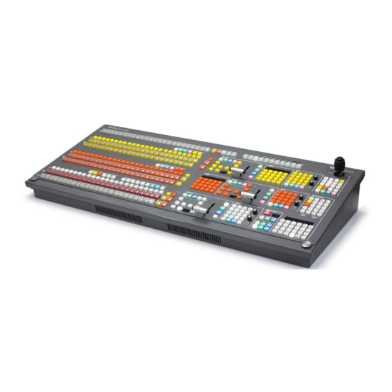
Page 21: Main Panel
System Components Main Panel The panel is organized into subpanels that contain groups of related con- trols (Figure The 3-M/E Main panel provides real time button, knob, and lever arm control of three full function mix/effects (PGM/PST with full M/E capa- bility). - Page 22 Section 1 — System Overview The Main panel power switches, fuses, reset buttons, and floppy drive are accessed by lifting the top of the Main panel (Figure Figure 3. Main Panel Inside View Crosspoint Switch Board Main Power Supply M/E Switch Board Control Panel Processor Board Boot Dial Switch (0)
-
Page 23: Menu Panel
System Components Menu Panel The Menu panel provides access to additional system controls that gener- ally do not require real time adjustment. The panel includes a touch screen display, control processor, five knobs for adjusting parameter values, built- in cooling fan, and a CD-ROM (Figure 4 on page 23). -
Page 24: Video Processor Frame
Section 1 — System Overview Video Processor Frame The Zodiak Video Processor frame houses most of the system electronics, with horizontal slots that hold individual system control, video routing, and signal processing modules. A built-in fan system allows cooling of the frame. -
Page 25: Video Processor Power Supply
System Components Video Processor Power Supply The Zodiak Video Processor frame houses up to three slide-in modules rated at 400 watts each. (Figure 5 on page 24). Two hot-swappable power supply modules (primary and redundant) are standard with the 2.5-M/E system, and three power supply modules are standard with the 3-M/E system. -
Page 26: Zodiak Facility Example
Section 1 — System Overview Zodiak Facility Example A basic facility configuration example of a Zodiak system is shown in Figure 6. Numerous types of sources can be fed to the Video Processor frame. Each M/E, Keyer and Utility bus has internal video processing capability to correct color (including optional RGB color correction) and add effects. -
Page 27: Functional Overview
Functional Overview Functional Overview Video Signal Flow The basic system architecture (Figure 7) of the Zodiak system has been designed for operational flexibility. For example, all the outputs from every M/E and the PGM/PST are routed back to the video crosspoint matrix, making all these signals accessible to the entire system. -
Page 28: Zodiak User Manual
Section 1 — System Overview Figure 7. Simplified Video Flow Diagram — Top Half Video or Key Signals Deserializer and Reclock Serializer Delay1 Input/Xpt/ Dual Mix Effect M/E 1 Inputs Sync Gen Key 1 Video Key 1 Video Key 1 Video Program M/E 1 Outputs Mixer... - Page 29 Functional Overview Figure 8. Simplified Video Flow Diagram — Bottom Half Video or Key Signals Deserializer and Reclock Delay Serializer Input/Xpt/ Single Mix Effect (3-M/E Switchers only) Sync Gen M/E 3 Inputs Key 1 Video Key 1 Video Key 1 Video Mixer Program M/E 3 Outputs...
-
Page 30: System Control
Section 1 — System Overview System Control Zodiak system control is designed for flexibility and simplicity. Ethernet, serial, parallel, and USB are used for system component interconnections. Tally and GPI control are available. Windows 2000 drives the Menu panel touch screen. An overview of Zodiak system control is shown in Figure Figure 9. -
Page 31: Section 2 - Concepts
Zodiak system can be re-configured to have different capabilities at different times. The way a Zodiak Digital Production Switcher is wired into your facility affects the Zodiak system’s capabilities. For example, the number and types of sources physically connected to the system obviously determines what video the system can handle. -
Page 32: Engineering Setups
Engineering Setups Engineering Setups control how the Zodiak Digital Production Switcher’s major components behave and interact, and how the Zodiak system inter- acts with the rest of the facility. -
Page 33: Suite Preferences
Zodiak System Configuration Overview Suite Preferences Suite Preferences define how the control surfaces associated with a Zodiak suite behave. Suite Preferences can substantially change system behavior, not just a user’s view of the system. Suite Preferences are intended for day- to-day or session-to-session changes in Zodiak system operating behavior and so are open for modification by operators. -
Page 34: Signal Routing
(commonly called video and key). Some incoming signals may also originate from devices the Zodiak system can control (Router, DPM, DDR). For a Zodiak Digital Production Switcher, the term source refers to all the video signals and other attributes associated with a device. This is a funda- mental concept. -
Page 35: Source To Button Mapping
Signal Routing Source definition data is stored as a part of Engineering Setups. Only one set of source definition data can be active on a Zodiak system at a time. Note that source definition is separate from source memory, which speci- fies what processing is to be applied to the source and can dynamically change during system operation. - Page 36 Section 2 — Concepts Buttons on a control panel can be used to control the switching of cross- points. The buttons are usually arranged horizontally, making it easy to imagine the available signals coming in from the top, and the single bus output signal going out the right side.
-
Page 37: Shifted Sources
Signal Routing Shifted Sources An operator may need to quickly access many sources during a production. However, a control panel has size limitations, since all the source selection buttons must remain within reach. The Zodiak system provides shifted buttons to allow access to more input sources from the control panel. On a 2.5- or 3-M/E Zodiak system, up to 46 sources can be mapped at one time, 23 to the unshifted source selection, and 23 to the shifted buttons. -
Page 38: Re-Entry
Section 2 — Concepts Figure 12. Simplified Mix Effects (M/E) Subsystem Source Signal Inputs Wipe Generator Key Fill Outputs Keyer Key Cut Crosspoint M/E Program Mixer Matrix M/E Preview Background A Background B The basic M/E shown in Figure 12 has an A and a B background bus. -
Page 39: Utility Buses
Signal Routing impractical, as the panel would become too large for an operator to reach all the buses. For ease of use, Zodiak panels have alternate buses accessed by delegation, using Key and PVW/AUX delegation subpanels. Utility Buses Besides the standard A and B background inputs, each Zodiak M/E also accepts Utility inputs. -
Page 40: Outputs
Section 2 — Concepts Outputs Video production switchers generate several different video outputs (Pro- gram, Preview, etc.). A final program output from PGM is typically sent to the transmitter for broadcast and/or to output devices for recording. Indi- vidual M/E program and preview outputs and an additional switched preview output are sent to monitors in the control room. -
Page 41: Resource Sharing And Point Of Use
However, changing the pattern shape affects both locations. Zodiak systems differ from the Grass Valley Group Model 4000 switchers in the division between wipe pattern generator and point of use. In the 4000, the edge is created as part of the generator so all points of use have the same softness and border width. -
Page 42: Transitions
Section 2 — Concepts Transitions A transition is a change from one image to another. The Zodiak system sup- ports four (three basic and one optional) types of transitions: • Cut • Mix • Wipe • DVE (optional) A transition can be applied to the entire picture, or to only the background or keyed elements of the picture, and can include multiple elements. -
Page 43: Wipe
Transitions Figure 14. Normal and FAM Mixes Start Start Crossfade Current Current Transition Transition Picture Picture Next Next Picture Picture Midpoint Midpoint Picture Intensity FAM transitions first fade a new picture to full intensity and then fade the old picture out, but both full intensity pictures are mixed together to the output during the transition. -
Page 44: Fade To Black
Section 2 — Concepts ator commands to complete. Preset Black can be used with any transition type (cut, mix, or wipe). The entire picture goes to black, even if all the tran- sition elements involved in the picture were not selected. Fade to Black The Fade to Black control in the DSK allows the Program output of the switcher to be brought down to black at a predetermined transition rate. -
Page 45: Current And Next Stack
Transitions Current and Next Stack Zodiak uses a current and next stack approach for transitions that involve multiple elements. The current stack is the current M/E output including any keys that are on. The next stack is defined by the current stack and whatever next transition elements have been selected. -
Page 46: Keying
Section 2 — Concepts Keying Keying inserts part of one picture into another to create a composite pic- ture. Keying involves three signals: • Background, • Key cut, used to specify where to cut a hole in the background, and •... -
Page 47: Shaping Video
Keying it with green matte video. This creates a green logo inserted into the back- ground (Figure 15). Because luminance values of the key cut signal are used to cut the hole in the background this is called a luminance key. Figure 15. -
Page 48: Key Control Signal Adjustment
Section 2 — Concepts summed with the background. Key fill video must be shaped using the key cut signal actually used to create the hole in the background. Video shaped with a different key cut signal will not key correctly. The Zodiak system, as well as some external devices like DPMs, can also divide a shaped video signal by its own key signal. -
Page 49: Clip And Gain
Keying Clip and Gain The Clip and Gain operation selects a threshold of the selected key cut video that will be used to cut the hole in the background video. Clip con- trols the threshold, and Gain controls the softness of the key edges and any translucent areas. -
Page 50: Clip Hi And Clip Lo
Section 2 — Concepts On the Zodiak system, Gain has a percentage value. A Gain value of 50% requires a luminance change of 50% of the distance between black and white to produce a keying signal ranging from transparent to opaque. A gain value of 100% (unity gain) uses the entire range between black and white for this transparent to opaque transition. -
Page 51: S-Shaped Key Signals
Keying S-Shaped Key Signals On the Zodiak system, an S-shaping function is applied to the edges of luminance keys. S-shaping smooths the sharp corners of a luminance key control signal, which helps prevent banding artifacts. S-shaping a signal minimally affects the key edges, and does not move key thresholds or affect the overall gain of the key (Figure 19). -
Page 52: Opacity
Section 2 — Concepts Opacity The opacity of a key can be adjusted. When opacity is reduced below 100% some background video is allowed to show through areas where it is nor- mally excluded. Key opacity is an adjustment to the overall intensity of the key, and is separate from Clip and Gain controls. -
Page 53: Fixed And Adjustable Linear Keys
Keying of the key cut signal determines where and how deeply the hole will be cut into the background. The intended soft edge and translucency of the key can then be faithfully reproduced (Figure 20). Figure 20. Linear Keying LOGO Key Hole in Background Background Video Invert... -
Page 54: Luminance Key And Self Key
Section 2 — Concepts Luminance Key and Self Key A luminance key uses the luminance of an incoming source to specify where to cut the hole in the background. The earlier example of a matte fill key is a type of luminance key. Luminance keying is typically done on sources that do not have an accompanying key cut signal, like a video camera. -
Page 55: Chroma Key
Keying Chroma Key A chroma key is a key that detects color (rather than luminance) in a video image and replaces it with a new background. For example, a reporter may be in a studio sitting in front of a backdrop with a blue or green backing color, and the new background can be a mountain scene. -
Page 56: Primary And Secondary Color Suppression
Section 2 — Concepts Chroma keys are performed by suppressing the backing color in the fore- ground scene, cutting a hole in the background, and then combining the two processed signals. When conditions are ideal, complete suppression of the backing color is possible and the hole cut in the background will match the suppressed foreground, permitting these two signals to be added suc- cessfully. -
Page 57: Preset Pattern
Keying Preset Pattern A preset pattern uses a wipe pattern generator, rather than an incoming key cut signal to define the hole cut in the background. Key clip and gain con- trols are not available for a preset pattern, but controls over the location, size, border, opacity, and edge softness are available. -
Page 58: Properly And Improperly Shaped Video
Section 2 — Concepts Note that if the key fill video has been shaped by an external device, this previously shaped video will not match the different key cut signal selected for the split key. Split keys normally treat the fill as unshaped since by def- inition a split key uses a fill that is not related to the cut. - Page 59 Keying When the shaping is configured properly (using either shaped or unshaped key fill) the desired output is the result (Figure 26). Figure 26. Correctly Shaped DPM Key Example When the DPM provides a shaped video output but the key is processed as though it were unshaped, the shaped video does not completely fill the key hole in the background so a dark halo appears around the key (Figure...
- Page 60 Section 2 — Concepts In this case the shaped input is incorrectly shaped again, sometimes called a double-multiply (Figure 28). Figure 28. Incorrect Keying with Shaped Input Correct Key Background Key Hole in Background Invert Key Control Incorrect Key with Dark Halo Shaping Circuit On Doubly-Shaped Shaped...
-
Page 61: E-Mem (Effects Memory)
E-MEM (Effects Memory) Grass Valley Group developed the E-MEM (Effects Memory) system to provide a way of storing effects for later use. An effect defines parameter settings that determine how the selected video sources are processed. An E-MEM effect is learned into an effect register, and can then be recalled at a later time with a single button press. -
Page 62: Keyframe
Section 2 — Concepts Keyframe A single set of processing control settings can be called a keyframe. A key- frame defines the state of all or a portion of the switcher. Keyframes are stored in E-MEM effect registers. Two types of information are associated with a keyframe: •... - Page 63 E-MEM (Effects Memory) The work buffer actually holds a copy of some of the effect register infor- mation. When an operator changes a control setting manually, the work buffer settings change but the effect register data itself remains unaltered (Figure 32).
-
Page 64: Banks And Registers
Section 2 — Concepts Banks and Registers The Zodiak E-MEM and Master E-MEM control panels are optimized for rapid recall of effects during live production. The Zodiak system’s 100 effect registers can be thought of as being organized into banks (numbered 0 to 9), with each bank containing ten registers (also numbered 0 to 9). - Page 65 E-MEM (Effects Memory) The only difference between a single and multiple keyframe effect is a mul- tiple keyframe effect can be run after it has been recalled. Running an effect changes the state of the system from keyframe to keyframe. During the effect run the values between the keyframes are usually interpolated (Figure 35).
-
Page 66: Effect Dissolve
Section 2 — Concepts Effect Dissolve Effect dissolve produces a smooth transition from the current state of the work buffer to the state defined in a recalled register. Effect dissolve first takes to the source and other button settings specified as a starting point in the effect register. -
Page 67: Effect Sequence
E-MEM (Effects Memory) Effect Sequence Effect sequence allows the operator to chain a set of specified effect regis- ters together. Recalling the first register can initiate a sequential recall of all the registers in the sequence. As each register is recalled, its settings will be applied to the work buffer and the appearance of the system’s output signals will change if they are affected. - Page 68 Section 2 — Concepts The earlier E-MEM discussion was simplified to explain basic concepts. Actually, register learn and recall operations and work buffer modifications apply to each level of an effect, though multiple levels of an effect can be changed simultaneously. Settings for each level’s E-MEM register is applied to the corresponding level of the work buffer (Figure 38).
-
Page 69: Master Timeline And Multiple Level Keyframe Effects
E-MEM (Effects Memory) Master Timeline and Multiple Level Keyframe Effects A master timeline exists to coordinate the activity of the individual level timelines. The master timeline contains a master timeline keyframe at every point in time where a keyframe exists on any of the level timelines. Keyframes from the levels are projected to the master timeline. -
Page 70: Number And Types Of E-Mem Levels
Section 2 — Concepts Number and Types of E-MEM Levels The Zodiak system supports a large number of E-MEM levels because of the many different sets of operating controls available. E-MEM levels for the following functional areas exist. • Each M/E primary partition •... -
Page 71: 300 Mode E-Mem Operation
The proceeding discussion explained the Normal E-MEM operating mode. 300 Mode is an alternative Master E-MEM method of operation that mimics the behavior of the Grass Valley Group Model 300 switcher. In this mode, Master E-MEM Learn operations store the register numbers of the indi-... -
Page 72: Default Keyframe
Section 2 — Concepts Default Keyframe An important E-MEM concept is the Default Keyframe. A Default Key- frame is a standard collection of effect settings. When the work buffer is cleared, the initial settings it receives will be those defined as the Default Keyframe. -
Page 73: Work Buffer, E-Mem, And Source Memory
Source Memory Work Buffer, E-MEM, and Source Memory When source memory is on, it tracks the work buffer’s source selection for each bus. Whenever a new source is selected on a bus, the last settings used by that new source are loaded into the work buffer from source memory. Source memory settings are automatically updated when corresponding values in the work buffer are changed. -
Page 74: Source Memory Organization
Section 2 — Concepts Source Memory Organization Each source on each Zodiak bus has its own source memory. Source memory parameters for each source are organized into groups to allow some settings to be remembered and applied independently to meet dif- ferent requirements (Figure 44). - Page 75 (Figure 45). This is different from the Grass Valley 4000 switcher, which associated its source memory only with the key fill signal. Figure 45. Source Memory and Split Key...
-
Page 76: Default Source Memory And Factory Default Source Memory
Section 2 — Concepts Default Source Memory and Factory Default Source Memory Default source memory settings can be set for every Zodiak source, and these defaults can be restored by an operator when desired (Figure 43). The defaults for a source are not bus specific. The same default values for a source are used on every Zodiak bus. - Page 77 3-D Digital Effects Concepts — Picture rotation about the reference axis in the X, Y, and Z dimen- Rotate sions (Figure 47). Rotate is limited to ± one half revolution, and will always take the shortest path to the new position. Rotate uses Quaternian math to calculate the move with increased accuracy.
-
Page 78: Axis Location
Section 2 — Concepts — Changing the viewer’s apparent viewpoint of a picture. This Perspective only applies when a picture is tilted so part of it is farther from the viewer. The farther portion appears smaller than the closer portion, and the amount of perspective controls how much smaller the distant part is (Figure 48). - Page 79 3-D Digital Effects Concepts Figure 50. Source and Target Space Transformed Picture Target Monitor Screen In this example the source space for the channel is referenced to the picture itself (tilted back at an angle) while the target space is referenced to the monitor screen (straight).
-
Page 80: Post Transform Space
Section 2 — Concepts Figure 52. Channel Translate with Global Rotated Logical Channel Source Translate Logical Channel Target Translate Along X-Axis Along X-Axis Figure 53. Global Channel Translate with Global Rotated Camera Channel Global Channel Source Translate Global Channel Target Translate Along X-Axis Along X-Axis Post Transform Space... -
Page 81: Front And Back, Near And Far
3-D Digital Effects Concepts All post transform functions are made relative to the monitor screen frame of reference. For example, a positive X post transform always moves to the right side of the screen. Front and Back, Near and Far Pictures manipulated by a Zodiak Transform Engine have front and back sides, each of which is revealed in turn as the picture spins or rotates. - Page 82 Section 2 — Concepts Figure 55. Screen Coordinates -16X +16X Screen units are also used to define Z axis dimension depth in 3-D space. Positive Z axis values are back behind the picture, and negative values are in front of the picture (Figure 56).
-
Page 83: Spin And Rotation Relationship
3-D Digital Effects Concepts Spin Spins are measured in number of 360° rotations (up to 999). Fractional spin values are also supported. A single axis 0.50 spin is the same as a single axis 0.50 rotation. Spin values can be positive or negative, which determines the direction of spin. -
Page 84: Path Control
Section 2 — Concepts Path Control Paths Keyframes specify parameter values at specific times in an effect. Most of the duration of an effect, however, occurs between these keyframes. The Zodiak system interpolates parameter values between keyframes (inbe- tweening). The trajectory, or path, a manipulated picture travels between keyframes is determined by how these inbetween values are interpolated. -
Page 85: Path Vectors
3-D Digital Effects Concepts The path concept can also be applied to functions that do not move a picture across the screen, like matte hue changes. For these functions, the rate of change of the parameter follows the same path types above. For example, an S-Linear hue rotation will accelerate and decelerate the speed of the hue change at the beginning and end of the keyframe. -
Page 86: Vector Values
Section 2 — Concepts Vector Values Path vector setting values of ± 1.0 are available, same as the Grass Valley Group Kaleidoscope DPM. Tension Control In the example below, the keyframes comprise a right angle, so the TENSION control operates on a 45° line drawn through the keyframe. This line is... - Page 87 3-D Digital Effects Concepts In the example below, the control is increased to 1.0, so that the TENSION Tension vector is shortened to non-existence through KF2 (Figure 61). The path enters and leaves the middle keyframe in a straight line as it takes on an S-Linear motion;...
-
Page 88: Continuity Control
Section 2 — Concepts Continuity Control The continuity adjustment determines the angle of the path into and out of the keyframe. It is represented by a vector 90 degrees to the tension vector (Figure 63). The unmodified path shown is identical to the unmodified path of the other controls. -
Page 89: Bias Control
3-D Digital Effects Concepts With continuity set to -1.0, the paths between the keyframes become straight lines, accelerating into the keyframe and decelerating as it leaves the keyframe (Figure 65). Figure 65. Continuity Control Setting -1.0 Continuity Vector – Continuity = -1.0 Bias Control control determines whether the path will be pulled towards the BIAS... - Page 90 Section 2 — Concepts With the bias set to 1.0, the path is pulled towards the following keyframe. Entry into and exit from the keyframe is a straight line from the previous keyframe, and the path of the effect travels completely through KF2 before turning towards KF3 (Figure 67).
- Page 91 3-D Digital Effects Concepts Zodiak User Manual...
- Page 92 Section 2 — Concepts Zodiak User Manual...
-
Page 93: Section 3 - Control Surface Description
Section Control Surface Description Introduction A basic Zodiak system is equipped with a Main panel, a Menu panel, and removable media drives. These separate control panel components make up a Zodiak control surface. Interactions occur between the components of the control surface. For example, changing controls on the Main panel can change the status of soft buttons on the Menu panel, and vice versa. -
Page 94: Single Press
Section 3 — Control Surface Description Single Press The most basic button behavior is a single press, where pushing the button activates the labeled function immediately. These buttons light while its action is being performed, and then go off, permitting the function to be activated again. -
Page 95: Double Press
Introduction Double Press Some buttons can be pressed twice rapidly to perform a different related function. For example, pressing the button once in the Effects Clear WkBfr Edit subpanel can clear basic work buffer parameters, but pressing twice can clear both the basic parameters and the source Clear WkBfr memory parameters from the work buffer. -
Page 96: Dialogs And Prompting
Section 3 — Control Surface Description Dialogs and Prompting Some operating procedures on the panel involve modifying button behavior until the procedure is completed or canceled. Prompting dialogs can be displayed to the operator during the procedure. One example is using the Master E-MEM key pad for numeric entry. -
Page 97: Automatic Subpanel Delegation
Introduction The following areas of the Zodiak Main panel use delegation: • Keyers subpanels • Key bus source selection rows • Joystick subpanel • E-MEM numeric keypads in each M/E • PVW/AUX bus source selection • Menu panes Automatic Subpanel Delegation The Zodiak system is designed so that when an operator activates a partic- ular object, one or more subpanels will automatically delegate to control the specific object involved. -
Page 98: Dpop And Spop Menu Delegation
Section 3 — Control Surface Description DPOP and SPOP Menu Delegation DPOP stands for Double Press Open. This is a form of automatic delegation where a specific menu is displayed on the Menu panel when a panel button is pressed twice in rapid succession. A menu can contain controls that do not exist on the Main panel. -
Page 99: Keypad Delegation
Introduction Keypad Delegation Each E-MEM and Master E-MEM has a keypad that can recall effects with a single numeric button press (see Keypad Numeric Entry Buttons on page 127 Master E-MEM Keypad on page 133). These keypads are also used to enter numeric values. Pressing a numeric prefix button delegates the keypad to numeric entry for that function. - Page 100 Section 3 — Control Surface Description To enter only fields, use two separators before the number. For example, a time of 30 fields (one half second on 60 hz systems) is entered by typing: • • Enter You can actually enter any combination of seconds, frames and fields. The Zodiak system will do the conversion and display the result in seconds, frame, field format.
-
Page 101: 2.5-M/E And 3-M/E Main Panel
2.5-M/E and 3-M/E Main Panel 2.5-M/E and 3-M/E Main Panel The Zodiak 2.5 and 3-M/E Main panel is designed as an intuitive, full-fea- tured production system. Both panels are very similar, differing only in appearance by the presence of additional key caps in the 3-M/E system. Sources are selected in the three M/E blocks on the left side of the panel (M/E 1, 2, and PGM PST or M/E 3). -
Page 102: Unshifted And Shifted Sources
Section 3 — Control Surface Description Holding down a source select button when recalling an E-MEM register performs a source override. That source will be held on that bus even if a register is recalled and/or run that specifies a different source. Note Different types of control are available for choosing which sources are subject to change during a Recall: Source Holds... -
Page 103: Re-Entry Buttons
2.5-M/E and 3-M/E Main Panel button is turned off. If the user toggles the button to the state Shift Shift that is opposite of the currently selected crosspoint, the button will blink, indicating this out of sync shift condition. In No Shift mode the Shift button acts like a standard source selection button. -
Page 104: Key Buses
Section 3 — Control Surface Description Key Buses The Key buses in each M/E and the PGM/PST are delegated to the avail- able keyers by the Key Bus Delegate subpanels in each section of the panel as described below. When a Keyer is selected in a subpanel, the currently selected source for that Keyer will light on the Key bus. -
Page 105: Source Button Tally
2.5-M/E and 3-M/E Main Panel Figure 73. PGM/PST or M/E 3 Key Bus Delegate Subpanel PGM/PST or M/E 3 Preview Bus Delegate Subpanel Key Bus Delegate Macro 2.5-M/E System Key Bus Delegate Util Macro 3-M/E System Source Button Tally A source button only lights if the selected source is mapped to a button on the bus and the correct shifted/unshifted bank is selected by the source select modifiers and shift preference. - Page 106 Section 3 — Control Surface Description button in the delegation group permits switched preview source selection on the primary PVW/AUX bus. When the button on PVW Primary the Main panel’s Preview subpanel is selected, the output of this bus is routed to switched preview (see Preview Subpanel on page 108), and you...
-
Page 107: Source Selection Buses
2.5-M/E and 3-M/E Main Panel Source Selection Buses Source selection on the PVW/AUX primary subpanel is identical to the Main panel. Twenty-three unshifted and twenty-three shifted source buttons are available on the primary bus. Five additional secondary source buttons ( ) are located to right of the M/E 1 M/E 2... -
Page 108: Preview Subpanel
Section 3 — Control Surface Description Preview Subpanel The Zodiak preview system consists of one preview output from each M/E, two preview outputs from PGM and PST (Preview A and Preview B), and a switched preview. Preview A and B show a DSK preview for PGM A and B respectively. -
Page 109: Transition Subpanels
2.5-M/E and 3-M/E Main Panel Transition Subpanels Each M/E on the Zodiak system, is functionally identical and provides complete mix, wipe, and keying capabilities. The Transition subpanel con- trols these compositing operations for each M/E and PGM/PST (or M/E 3 in a 3-M/E system). -
Page 110: Main Transition Controls
Section 3 — Control Surface Description Main Transition Controls The transition controls are used to select the signal elements that will be involved in the transition (background or keys), define the type of transi- tion, and perform the transition. Transition Elements buttons select the elements that will change during Key 1 –... - Page 111 2.5-M/E and 3-M/E Main Panel button selects a wipe as the next transition. Each wipe is pre- Wipe defined using either the complex wipe generators or the Utility buses as the wipe shape. Wipe pattern selections are made in the Wipe menu (see Wipe Menus on page 322), which these buttons DPOP to.
- Page 112 Section 3 — Control Surface Description Two successive transition commands ( button, button, or Auto Trans Tran- action) are used for a complete preset black transition. The sition Lever Arm first command transitions the M/E to black (first stage). When in black, both the A and B bus selections will go low tally.
-
Page 113: Keyer Transition Controls
2.5-M/E and 3-M/E Main Panel Keyer Transition Controls Each keyer has its own mix transition system, separate from the main M/E transition mechanism. Individually numbered buttons located Key 1-4 Mix to the right of the control these transitions. These buttons Transition Lever Arm can directly change the output of the M/E. -
Page 114: M/E Keyer Subpanels
Section 3 — Control Surface Description For example, if the lever was moved halfway and the transition is com- pleted by pressing at a rate of 200 frames, the remaining half of Auto Trans the transition will take 100 frames. Moving the lever part way, then pressing will complete the transition with a cut. -
Page 115: Clip And Gain Knobs
2.5-M/E and 3-M/E Main Panel Hold to Preview When setting up a key, it is often desirable to see a key that is not on air or part of the next transition. Holding down a delegation button will Key 1-4 replace that M/E’s preview output with a representation of that key over the current background. -
Page 116: Key Source Button Group
Section 3 — Control Surface Description Note Linear Key mode produces a proper key if the source has been set up and defined properly. If not setup properly, you can compensate by selecting Adjustable Linear mode. Adjustable Linear Key An adjustable Linear Key can be selected by pressing the Lin Key Lum Key buttons simultaneously. -
Page 117: Key Split Button
2.5-M/E and 3-M/E Main Panel Matte Fill Button button determines what signal will be used as the key fill by Matte Fill the keyer. When off, the key fill signal currently selected on the fill bus will be used. When on, a matte signal will be used. Selecting the button Matte Fill automatically delegates the Matte menu in the Menu panel. -
Page 118: Key Prior Button
Section 3 — Control Surface Description Key Prior Button button allows the user to set a different priority of the four Key Prior keyers in the M/E. To set key priority, hold down the button and Key Prior press the buttons in the keying order desired, from top to bottom Key 1 –... -
Page 119: Dsk Keyer Subpanel
2.5-M/E and 3-M/E Main Panel DSK Keyer Subpanel The DSK Keyers subpanel in a 2.5-M/E system (Figure 79) has a reduced set of functions as described below. The Keyers subpanel operates in par- allel with the DSK subpanel including the On status indicators (see Subpanel on page 121). -
Page 120: Key Source Button Group
Section 3 — Control Surface Description Luminance Key button selects a Luminance key. The Gain/Clip Hi Clip/Clip Lo knobs provide a full range control of clip and gain. Key Source Button Group buttons in the DSK Keyers subpanel determine Matte Fill Video Key the source of the key cut and key fill for each key as explained below. -
Page 121: Dsk Subpanel
2.5-M/E and 3-M/E Main Panel DSK Subpanel In both 2.5 and 3-M/E systems the DSK subpanel (Figure 80) allows control of the three DSK keyers. This subpanel works in parallel with the DSK Keyers subpanel in a 2.5-M/E system. Figure 80. DSK Subpanel Subpanel DSK Key Delegate Button Group (3) -
Page 122: Fade To Black Subpanel
Section 3 — Control Surface Description Fade to Black Subpanel Pressing the button fades the switcher’s Program output to Fade To Black black at the transition rate shown in the display to the right of the button (Figure 81). The button will light to indicate that a fade to black transition is in progress. -
Page 123: Joystick Subpanel
2.5-M/E and 3-M/E Main Panel Joystick Subpanel The Joystick subpanel (Figure 82) is used to control Joystick functions and delegation and Transform Engine image and wipe pattern placement, size, angle, and other attributes in conjunction with the Transform menus in the Zodiak Menu panel application (see (Transform Menus on page 273). -
Page 124: Joystick
Section 3 — Control Surface Description Joystick The Zodiak system Joystick is a precision three-axis device. Moving the Joystick towards or away from you controls the Y-axis, moving the Joystick left and right controls the X-axis, and rotating the Joystick controls the Z- axis (Figure 83). - Page 125 2.5-M/E and 3-M/E Main Panel For example, it is possible to delegate the Joystick to M/E 2 Key 1 and Key 2 where Key 1 has a Transform Engine and Key 2 does not. In this case, the Key 1 button will be high tally but the Key 2 button will low tally. Keyer Delegation Buttons The four delegation buttons select a specific component of the delegated M/E to be controlled by the...
-
Page 126: Axis Buttons
Section 3 — Control Surface Description Axis Buttons Holding down the , and axis buttons individually or in any combina- tion constrains the Joystick parameter changes to the selected axes. For example, if the button is held down while the Joystick is moved, then only X axis deflection is performed. -
Page 127: Keypad Numeric Entry Buttons
2.5-M/E and 3-M/E Main Panel Keypad Numeric Entry Buttons The E-MEM keypad has 12 numeric entry buttons ( ). These Undo/• Enter buttons are used to recall registers directly or to enter numeric values in conjunction with the prefix buttons for other functions (see below). Same Bank Effect Recall The default use of the keypad when a prefix button is not active is to recall an effect to that M/E. - Page 128 Section 3 — Control Surface Description Up Arrow Bank Button prefix button operates as a shift button to provide two modes of ↑ Bank operation for other buttons. The actual operating mode is determined by what other button is pressed next. The first operating mode is used to specify a bank number.
- Page 129 2.5-M/E and 3-M/E Main Panel To learn M/E settings to a register in a different bank, the new bank must be specified. One of the bank selection procedures described above is used. Lock/Learn bank selection register number The learned register becomes the current effect. Subsequent register selec- tions will be from that new bank unless a different bank is selected before the operation.
- Page 130 Section 3 — Control Surface Description Effect Dissolve Button button is used to specify an effect dissolve from the current Effect Dis state of the work buffer to the first key frame of a new register (see Effect Dissolve on page 66).
-
Page 131: Run Control Button
2.5-M/E and 3-M/E Main Panel Enter Button button on the E-MEM subpanel is only used to complete a time Enter value entry on that keypad for an Auto Transition, Effect Dissolve, and Sequence Delay. Undo / • Button The E-MEM button is used to enter default values and decimal Undo/•... -
Page 132: E-Mem Readout Display
Section 3 — Control Surface Description E-MEM Readout Display The E-MEM readout display has 16 alphanumeric characters, and is used to show the status of the current register status, display messages, and prompt the user. When displaying the status of the current effect, the first readout character position is either blank or indicates with an “L”... -
Page 133: Master E-Mem Subpanel
2.5-M/E and 3-M/E Main Panel Master E-MEM Subpanel The Master E-MEM subpanel (Figure 87 on page 134) is organized in a similar manner to the individual E-MEM subpanels, but has additional capabilities. The Master E-MEM subpanel can also Learn and Recall effects for all the other M/Es, individually or in combination. - Page 134 Section 3 — Control Surface Description Figure 87. Master E-MEM Subpanel Master E-MEM Auto Auto Clear Recall Work Buffer Misc Previous Next Master E-MEM Keyframe Edit Misc Copy Subpanel Enable Buttons Controls Button Group (11) Misc Modify Paste Still Insert Insert Store Before...
-
Page 135: Master E-Mem Enable Buttons
2.5-M/E and 3-M/E Main Panel keypad button, when shifted with the ↑ button, changes the +/- | 0 Bank sign of the value currently being input on the Master E-MEM keypad. This button can be pressed either before or after the value has been typed into the keypad, but before it is completed with . -
Page 136: Master E-Mem Readout Display
Section 3 — Control Surface Description Master E-MEM Readout Display The Master E-MEM readout is organized the same as the individual E-MEM readouts. See E-MEM Readout Display on page 132. The Master E-MEM readout can also display additional level related information, and shows different prompts for the other Master E-MEM keypad prefix func- tions (Figure... -
Page 137: Hold Inputs Button
2.5-M/E and 3-M/E Main Panel Rew Button Pressing will abort any run in progress and rewinds the effect to its beginning (if is off) or to its end (if is on). Hold Inputs Button button can be used to control whether E-MEM recalls will Hold Inputs change any of the current source selections on any Zodiak system bus (including the Aux buses). - Page 138 Section 3 — Control Surface Description When source memory is on, the following actions can be performed with button: Clear Wk Bfr • Pressing once clears all the work buffers parameters except Clear Wk Bfr those associated with source memory in all levels enabled in the Master E-MEM subpanel.
- Page 139 2.5-M/E and 3-M/E Main Panel – Pressing the button moves the cursor to the previous Previous Previous master timeline keyframe. Next – Pressing the Next button moves the cursor to the next master timeline keyframe. – Pressing the button removes the currently marked keyframe(s) from the timeline and stores it on the clipboard, completely replacing any current clipboard contents.
-
Page 140: Auto Run Button
Section 3 — Control Surface Description Auto Run Button button on the Master E-MEM subpanel controls whether a Auto Run multiple keyframe effect will run when it is recalled. When on, the effect will immediately run when recalled. When off, the effect will remain on its first keyframe when recalled. -
Page 141: Remote Aux Panels
Remote Aux Panels Remote Aux Panels There are five different Remote Aux panel options available with the Zodiak system. The panels come with either 24 or 32 primary source buttons and can be single or multi-destination. Operation of Remote Aux panels is similar to the local PVW/AUX subpanel on the Main panel. -
Page 142: 32-Crosspoint Remote Aux Panels
Section 3 — Control Surface Description The single bus Remote Aux panels control only one Aux bus. The multi- destination panel has 18 Aux bus delegation buttons that may be config- ured to control any of the available Zodiak Aux buses. Aux bus delegation mapping and source to button mapping is described in detail in Button Mapping on page... -
Page 143: Source Select Modifier Buttons
Remote Aux Panels Source Select Modifier Buttons Hold Button button on each panel is alternate action, either on or off. When on Hold (high tally), the button prevents an E-MEM recall from the Main panel Hold from changing the source selection on the bus (a bus hold). Shift/Unshift Buttons source select modifier buttons are used to select the Unshift... -
Page 144: Disk Drives
Section 3 — Control Surface Description Disk Drives The Zodiak file system includes a CD-ROM drive installed in the side of the Menu panel used to load software files and an external 250 Mb Zip disk connected to the menu panel used for saving and loading configuration and effect files. -
Page 145: Section 4 - Menus Overview
Section Menus Overview Introduction The Zodiak system’s Menu panel provides capabilities that complement the operation of the Main panel and the Remote Aux panels. The Menu panel controls most system functions, and has additional controls not available on the Main panel (for example, wipe pattern selection, chroma key manual controls, and configuration menus). -
Page 146: Touch Screen
Section 4 — Menus Overview Touch Screen CAUTION Do not apply any sharp or rigid object (no pens or pencils) to the touch screen display surface. The Menu panel touch screen allows direct interaction with menu controls displayed on the screen. The screen is designed to work with a finger or other soft object. -
Page 147: Menu Screen Organization And Components
Menu Screen Organization and Components Menu Screen Organization and Components Zodiak system menus are context sensitive. They display different infor- mation and provide various types of controls depending on what area of the system is involved. Menus are organized into categories of related con- trols, which can be directly selected with touch buttons located at the bottom of the screen. -
Page 148: Data Pads And Touch Buttons
Section 4 — Menus Overview Data Pads and Touch Buttons The Zodiak system menus make extensive use of data pads. Data pads are active areas on the screen that display a summary of the status of an object, and when touched bring up additional controls and information for that object. -
Page 149: Menu Top Line
Menu Screen Organization and Components Menu Top Line The top line is identical in all the Zodiak system menus. The left portion of the top line identifies the name of the current menu. The selected subcate- gory or specific mode is also displayed when appropriate. The right portion of the top line is an operator notification area, where messages gen- erated by the Zodiak system are displayed. -
Page 150: Parameter Control Area
Section 4 — Menus Overview Parameter Control Area In the Keyer menu example, a Parameter Control area contains function selection touch buttons and soft knob pads for the selected operating mode. Function selection touch buttons either toggle on and off or are part of an interlocked group.The soft knob pads on the right allow individual param- eter adjustments, as described earlier. -
Page 151: Alphanumeric Keypad
Menu Screen Organization and Components Alphanumeric Keypad Touching the pad for a text parameter brings up an alphanumeric keypad (Figure 98). You can also use a standard computer keyboard to enter infor- mation while this display is active. Figure 98. Alphanumeric keypad Scrolling Selections Sometimes it is not possible to display all the available selections on a menu screen. -
Page 152: Menu And Panel Interactions
Section 4 — Menus Overview Figure 99. Daily Setups - Local Aux Delegation Menu Example Touching an arrow on the top or bottom of these displays scrolls that area to the next group of available items. The white area of the scroll bar is used to scroll the entire page. - Page 153 Menu Screen Organization and Components selected on the Main panel, the menu display will change its delegation to M/E 2 Key 2. However, the reverse is not true. Changing delegations on the Menu panel does not change Main panel delegations. When both the Main panel and the Menu panel are delegated to the same object (say, M/E 1, Key 1), changes can be made to that object from either panel.
-
Page 154: Menu Summaries
Section 4 — Menus Overview Menu Summaries In the remainder of this chapter, figures of several Zodiak system menus are presented to familiarize you with various screen layouts. Cross refer- ences are provided for more detailed information. Because each menu con- trols different aspects of the Zodiak system, the screen parameters and organization will vary, but the basic principles previously described are fol- lowed. -
Page 155: Home Menu
Home Menu Home Menu The Home menu (Figure 101) is used to access the Zodiak system menus. Touch the button of the desired menu type to go directly to that menu. If multiple menus are available for that type, the last selected menu will be displayed. -
Page 156: Home Menu Window Management Buttons
154. Touch anywhere in the Zodiak title to return to the Home menu. To return to the splash with top menu line, touch the Grass Valley Group logo on the bottom of the screen. – Minimizes the Zodiak Menu down to the Windows Task Minimize Menu Bar. -
Page 157: Daily Setups Menus
Daily Setups Menus Daily Setups Menus The Daily Setups menus contain controls operators may need to change routinely to meet various project requirements. Daily Setups Save-Load Menu The Daily Setups Save-Load menu employs the Zodiak file browser and is used to save and load User Profiles, Suite Profile, and Source Memory information to disk. -
Page 158: Profiles Menu
Section 4 — Menus Overview Profiles Menu The Profiles menu is used to load User Profile and Suite Profile files from specific folders on the Video Processor frame hard disk or Zip disk. Only these file formats are supported in this menu. The menu is accessed by touching Daily Setups, Profiles (Figure 103). -
Page 159: Default Keyframe Menu
Daily Setups Menus erences, touch . Various Suite Preference controls are Daily Setups Suite Prefs available by selecting a subcategory touch button on the left side of each menu. Default Keyframe Menu The Default Keyframe menu is used to learn the current Zodiak panel state to the system’s Default Keyframe, and to set the Default Keyframe back to factory settings. -
Page 160: E-Mem Prefs Menu
Section 4 — Menus Overview E-MEM Prefs Menu E-MEM Prefs menu is used to set the E-MEM level assignments. The menu is accessed by touching (Figure 105). Daily Setups Suite Prefs E-MEM Prefs Figure 105. E-MEM Prefs Menu E-MEM Sublevel to Enable Button Assignment The Zodiak E-MEM system has many levels (M/E 1 -3, PGM PST, etc.) and sublevels (Still Store outputs, Aux buses, etc.), the actual number depending on installed options and external devices. - Page 161 Daily Setups Menus The default assignments for each level are shown in Table Table 5. E-MEM Level Default Assignments E-MEM Sublevel Default GPI out Misc 1 Still Store outputs Still Store Aux buses Misc 1 Bkgd 1 and 2 Misc 1 DPM 1 and 2 Misc 1 Peripheral Bus II...
-
Page 162: Master E-Mem Mode
Master E-MEM Mode 300 Mode is an alternative Master E-MEM method of operation that mimics the behavior of the Grass Valley Group Model 300 switcher. In this mode, Master E-MEM Learn operations store the register numbers of the indi- vidual M/Es, allowing the recall of different combinations of M/E registers with a single button press. -
Page 163: Video Settings Menu
Daily Setups Menus Video Settings Menu The Video Settings menu is used to set video standards to be used by the Zodiak system. This menu is accessed by touching Daily Setups Suite Prefs (Figure 107). Video Settings Figure 107. Video Settings Menu Line/Fields The Line/Fields mode of operation displayed is a read-only field deter- mined by the reference in signal provided to the system. -
Page 164: Aspect Ratio
Section 4 — Menus Overview – This limiter mode is similar to Decodable, except that maximum Both levels are reduced slightly around yellow and cyan to prevent over modu- lating an NTSC transmitter. – In this mode, no limiting is imposed. Analog signal paths and mon- None itors may behave poorly to some colors produced in this mode. -
Page 165: Gpi In Settings Menu
Daily Setups Menus If an image smaller than expected is transformed, black lines can occur at its edges, which are now visible because they have moved inside the visible picture area. SMPTE has published recommended practices for standard image sizes (production aperture, clean aperture). If a facility conforms to these practices, the system default values will be correct and no adjustment should be necessary. -
Page 166: Source Patch Menu
Section 4 — Menus Overview • Effect Run. Refer to the following sections of the Zodiak Installation and Service Manual for GPI input connection and configuration information: • Section 2 – Installation – describes how to connect the physical GPI inputs to the GPI port on the rear of the Video Processor frame. -
Page 167: Logical Source Selection Pane
Daily Setups Menus Logical Source Selection Pane The Source Patch menu has a scrolling list of Logical sources displayed in ascending Logical ID order. The Logical Source soft knob can be used to scroll up and down the list and select a different Logical source. Touching the soft knob label data pad brings up a numeric keypad that can be used to scroll the list to the entered Logical ID number and select that source. -
Page 168: Using Source Patching For Effects Portability
Section 4 — Menus Overview Engineering source selection is also possible using a source picker. Touching an Engineering Source data pad in the Logical source selection pane brings up a scrolling Engineering source picker (Figure 110). Figure 110. Source Patch Engineering Source Picker Touching an Engineering source button associates that source to the cur- rently selected Logical source. - Page 169 Daily Setups Menus Plan out the sources you will use for a show, even ones that may not exist on the system where you are creating the effects. Build a list of Logical sources in the Source Patch menu without regard to the currently associ- ated Engineering sources.
-
Page 170: Source Memory Menu
Section 4 — Menus Overview Source Memory Menu The Source Memory menu is used to enable and disable Source Memory. page 72 for background information on Source Memory. The menu is accessed by touching (Figure 111). Daily Setups Suite Prefs Source Memory Figure 111. -
Page 171: Key Drop Menu
Daily Setups Menus Key Drop Menu A Key Drop menu is accessible from the Daily Setups-Suite Prefs menu. An On Air, hot cut will turn off all linked keys as selected for each M/E. Figure 112. Key Drop Menu Zodiak User Manual... -
Page 172: Bus Linking Menu
Section 4 — Menus Overview Bus Linking Menu The Bus Link menu allows the operator to set up bus links and source asso- ciations and enable the linking. This menu is accessed via Daily Setups, Suite Prefs, Bus Linking (Figure 113). -
Page 173: Bus Picker
Daily Setups Menus Bus Picker Touching the data pad at the top of either the Controlling Bus or Linked Bus pane facilitates selecting a bus via a popup bus picker (Figure 114). Figure 114. Bus Picker Popup The type of bus to display ( ) is chosen with the Bus M/E Buses Aux Buses... -
Page 174: Source Associations
Section 4 — Menus Overview Source Associations Selecting a button in the Controlling Bus pane delegates the Linked Bus pane to that Controlling source (Figure 113 on page 172). Selecting a button in the Linked Bus pane associates that new Linked bus source to the cur- rently selected Controlling bus source. -
Page 175: Shortcut Menu
Daily Setups Menus Shortcut Menu Touching the button brings up a menu that can help Display Shortcut Menu reduce the time required to build Link Mapping tables (Figure 115). Figure 115. Bus Linking Shortcut Menu The current Controlling Bus and Linked Bus are identified in the data pads at the top of the pane. -
Page 176: Copy Link Mapping Table
Section 4 — Menus Overview To choose a different Linked bus source for same source mapping, touch the Linked Bus Source data pad to go to the Bus Linking menu selection menu. Select the desired Linked Bus source from the scrolling list, then touch to return to the Shortcut menu. -
Page 177: User Prefs Menus
Daily Setups Menus – Enables the bus link, same as the Controlling bus Link Enable Link Enable the Bus Linking menu. – Breaks the link between the buses. After the link is broken that Break Link pair of buses is deleted from the menu. It is therefore not possible to undo the Break Link operation. -
Page 178: Button Mapping Menu
Section 4 — Menus Overview Button Mapping Menu The Button Mapping menu is used for source to button mapping on local and remote panels, which permits arranging sources in any order on the source selection button rows. On the Zodiak system, each bank on the Main Panel has the same source to button mapping. -
Page 179: Shift Preferences Menu
Daily Setups Menus Shift Preferences Menu The Shift Preferences menu (Figure 118) is used to configure the Shift mode of the source selection buttons. The menu is accessed by touching Daily Setups User Prefs Shift Prefs. Figure 118. Shift Preferences Menu Normal Mode button at the far right of each bus allows access to 23 additional Shift... -
Page 180: No Shift Mode
Section 4 — Menus Overview No Shift Mode You can configure the Zodiak system to have 24 source selection buttons on the Main panel. In this mode, the farthest right button becomes a Shift normal source selector like the other buttons. No shifted sources are avail- able directly on the M/E bus in this mode. -
Page 181: Aux Deleg Mapping Menu
Daily Setups Menus Aux Deleg Mapping Menu The Aux Deleg Mapping menu (Figure 119) is used to map the delegation buttons on the local PVW/AUX panel and any optional Remote Aux panels to control the desired (logical) Aux bus. The menu is accessed by touching Daily Setups User Prefs... -
Page 182: Clip Hi Lo Preferences Menu
Section 4 — Menus Overview Clip Hi Lo Preferences Menu The Clip Hi-Lo Preferences menu controls how Clip and Gain knobs behave. The menu is accessed by touching Daily Setup User Prefs Clip Hi-Lo (Figure 120). Prefs Figure 120. Clip Hi-Lo Prefs Menu The Clip and Gain knobs on the Zodiak system Main panel and Menu panel can control either Clip and Gain, or Clip Hi and Clip Low, depending on the preference set (see... -
Page 183: Eng Setups Menus
Eng Setups Menus Eng Setups Menus The Eng Setups menus contain controls generally used by engineering per- sonnel to set up and configure the Zodiak system. Note Engineering Setups configuration procedures are covered in more detail in the separate Zodiak Installation and Service Manual. Eng Setups Save-Load Menu The Eng Setups Save-Load menu employs the Zodiak file browser and is used to save and load Engineering Setup information. -
Page 184: Source Definition Menu
Section 4 — Menus Overview Source Definition Menu Engineering sources are defined in the Source Definition menu, accessed by touching (Figure 122). Eng Setup Source Definition Figure 122. Source Definition Menu Touch the Engineering Name data pad to bring up a keypad to enter the desired name. -
Page 185: Outputs Menu
Eng Setups Menus Outputs Menu The Eng Setups – Outputs menu is used to assign the Zodiak system Aux Buses to the physical output destinations on the rear of the Video Processor frame. The menu is accessed by touching (Figure 123). -
Page 186: Ports & Devices Menu
Section 4 — Menus Overview Ports & Devices Menu The Eng Setups – Ports & Devices menu is used to define external devices to interface to Zodiak. The menu is accessed by touching Eng Setup Ports & (Figure 124). Devices The setup for each type of device is described in detail in Appendix C –... -
Page 187: Tally Menus
Eng Setups Menus Tally Menus The Tally menus are used to configure the tally system. There are multiple tally calculators, three different tally calculation methods, and user assign- ment of tally relays. The results of the tally calculators are applied to the tally relays on the Tally modules in the Video Processor frame, and those relays control external tally lights. -
Page 188: Tally Relay Assignments Menu
Section 4 — Menus Overview Tally Relay Assignments Menu Touch (the Relay Assign button is in the Tally Eng Setup Tally, Relay Assign pane) to access the Tally Relay Assignments menu (Figure 126). Figure 126. Tally Relay Assignments Menu Zodiak User Manual... -
Page 189: Router Interface Setup Menu
Eng Setups Menus Router Interface Setup Menu The Router Interface Setup menu (Figure 127) is used to set the IP Address(es) the Zodiak system will use to communicate to the external router. The Connection Status indicator is red when communication is not detected, and is green when communication is established. -
Page 190: System Menus
Section 4 — Menus Overview System Menus The System menus are used to identify the Zodiak Frame and Main panel IP address ( ), and configure Remote Aux panels ( ). Subcate- Config Aux Panel gory selection buttons for these controls are located on the left. Other con- trols on this menu are currently inactive in released software. -
Page 191: Aux Panel Menu
Eng Setups Menus Aux Panel Menu The Aux Panel menu is used to configure optional Remote Aux panels in the Zodiak system. The menu is accessed by touching Eng Setup System (Figure 129). Panel Complete instructions for configuring Remote Aux panels is given in Section 3 –... -
Page 192: Install Options
Section 4 — Menus Overview Install Options The Eng Setup – Install Options menu (Figure 130) is used enter an autho- rization code to enable software options that have been purchased after switcher delivery or are being tried on a temporary basis. This menu is reached by touching the category selection button on any Eng Install Options... -
Page 193: Macro Menus
Macro Menus Macro Menus The Macro menus provide access to many Zodiak system macro functions. The Macro menus can be used to: • Record a new macro and append record onto an existing macro, • Insert time delays between macro steps, •... -
Page 194: Macro Catalog Menu
Section 4 — Menus Overview This menu operates the same as the other save load menus (for example, E-MEM, Eng Setup, and Daily Setups Save-Load). You can select all macro registers, or a range of macro registers, to save to disk. You can also load a single macro, or load a folder containing several macros. -
Page 195: Control Pane
Macro Menus change its name. If a macro register is named but no macro steps are recorded, the name of the empty macro will be deleted the next time the system is rebooted. The memory size of each macro, to the nearest kilobyte, is displayed for each recorded macro. -
Page 196: Append Macros Pane
Section 4 — Menus Overview Append Macros Pane You can append the contents of one macro into another macro using the Macro Catalog menu. After touching either the button on Record Append the menu, touching another Macro Register button on the menu opens an Append Macros pane (Figure 133). -
Page 197: Soft Knob Register Selection
Macro Menus Soft Knob Register Selection Macro registers can be selected using the labeled soft knob on the right, and a specific register number can be entered on the data pad to go directly to that register. E-MEM Pane The E-MEM pane is used to add a macro to an E-MEM. Touching the E-MEM data pad opens the Macro selection menu, from which you select the desired macro. -
Page 198: Macro Copy Swap Menu
Section 4 — Menus Overview Macro Copy Swap Menu The Macro Copy/Swap menu (Figure 134) is accessed by touching the category selection button at the bottom of the Macro menu. Copy Swap Figure 134. Macro Copy Swap Menu Macro register information can be moved from one register to another with this menu by selecting the registers in the From and To scrolling panes, then touching the action buttons on the lower right. -
Page 199: Macro Attach Menu
Macro Menus Macro Attach Menu The Macro Attach menu (Figure 135) is accessed by touching the cat- Attach egory selection button at the bottom of the Macro menu. Figure 135. Macro Attach Menu Panel Attach Mode Pane Macros can be attached to other panel buttons so the macro runs when that button is pressed. -
Page 200: Macro Attachments Pane
Section 4 — Menus Overview Macro attachments are broken by entering one of the attach modes (it doesn’t matter which one) and, without a macro register selected, pressing the panel buttons with attachments you wish to remove. This attaches no macro to that button. -
Page 201: File Operations Menu
File Operations Menu File Operations Menu The File Operations menu employs the Zodiak file browser. This menu is used to navigate through the available file hierarchies, create folders, rename folders and files, and copy/paste files. Only mapped network drives and selected areas of the Zodiak system are accessible. The menu is reached by touching (Figure 136). -
Page 202: Status/Diags - Versions Menu
Section 4 — Menus Overview Status/Diags – Versions Menu The Versions menu displays currently loaded software versions for all the Zodiak system components (Figure 137). Touch to access this Status & Diags menu. Figure 137. Versions Menu A Memory Usage bar graph displays the amount of E-MEM keyframe memory currently in use. -
Page 203: External Device Menus
External Device Menus External Device Menus The External Device menus are used to control external devices, such as tape machines (VTRs) or digital disk recorders (DDRs), with the Zodiak Menu application and switcher E-MEMs. The external devices must be defined and configured in the Eng Setup, Ports & Devices menu and assigned to an E-MEM group level before they will be available for control. -
Page 204: Enables Device Pane
Section 4 — Menus Overview Figure 138. External Device – Enables Menu Disabling device control temporarily can be useful. For example, during a rehearsal you may not want to cue or roll VTRs. With the External Device Enables menu you can control which devices will respond without having to rebuild effects or change engineering configuration. -
Page 205: Enables Device Status
External Device Menus Enables Device Status Next to each device button is a status indicator, reporting the state of the interface to that device. • A green box indicates the device is controllable from the Zodiak Avail system. • A yellow box indicates the device is responding, but is in use Other User by another control point and has been locked from Zodiak system con-... - Page 206 Section 4 — Menus Overview so it is the responsibility of the user to map the correct number of sources based on the protocol used by the editor device. For example, if the editor uses the 200/250 protocol, then only the first 20 sources can be used. Figure 140.
-
Page 207: Dpm Panes
External Device Menus button accesses a Mapping Shortcuts for Editor Mapping Shortcuts window, see Figure 144. Figure 141. Editor Map Sources Menu • Touching the button does a quick mapping of the sources Map Sources 1:1 1 to 1, (Switcher Source 1 to Editor Source 1). •... - Page 208 Section 4 — Menus Overview is On and is On. Switcher Controls DPM DPM Controls Aux bus The switcher changes to the aux bus are sent as a request to the DPM. The DPM replies to the switcher with the report of the new source. Switcher receives the request and changes the source on the Aux Bus.
- Page 209 External Device Menus button accesses a Mapping Shortcuts for Editor Mapping Shortcuts window, see Figure 144. Figure 144. DPM Map Sources Menu • Touching the button does a quick mapping of the sources Map Sources 1:1 1 to 1, (Switcher Source 1 to Editor Source 1). •...
-
Page 210: External Device Time Code Selection
Section 4 — Menus Overview External Device Time Code Selection On the External Device Enables menu you can specify what type of time- code the Zodiak system will use with each device. The current time code mode is displayed in the Time Code column (Figure 138 on page 204). -
Page 211: Device Pane
External Device Menus You must define what E-MEM level group the external device will be a part of in the E-MEM Prefs menu (see E-MEM Prefs Menu on page 160). Note This menu directly affects the Zodiak system work buffer, not the effect key- frames themselves. -
Page 212: Events Summary
Section 4 — Menus Overview Events Summary The Event Summary data pads to the right of each status box display the currently enabled external device events (if any) in the work buffer for that device. Touching this data pad delegates the pane on the right to that device, where the external device triggers can be selected (see Events Pane below). -
Page 213: External Device Control Menu
External Device Menus External Device Control Menu The External Device Control menu is available to directly control a DDR or VTR. Touch to access this menu (Figure 147). Extern Device Control Figure 147. External Device Control Menu The pane on the left provides full control of one device. The three panes on the right provide limited control of each of those devices. -
Page 214: Device Name
Section 4 — Menus Overview the data pad brings up a keypad for entering the play speed. A variable play speed set in the larger left pane is retained for use on that device if control is swapped to a smaller pane on the right. Pressing the smaller pane’s button plays that device at the speed that was set for that device Play... -
Page 215: Preset And Program Clip
External Device Menus Preset and Program Clip Devices that allow clip selection (DDRs for example) are loaded with a spe- cific clip with the data pads. Touching these pads Preset Clip Program Clip bring up a clip picker menu. If the device is using the optional AMP Serial Machine Control feature, both folder and clip selections are available (Figure 149). -
Page 216: Clip Browser
Section 4 — Menus Overview The External Device Event List menu is accessed by touching Extern Device (Figure 150). The Event List itself appears in the right pane, list Event List editing controls appear in the central pane, and a clip browser from which clips are selected appears in the left pane. -
Page 217: List Edit
External Device Menus clips are stored in a News8 folder, and others are stored in a News10 folder, the clips in the News10 folder will appear above those in the News8 folder (1 precedes 8). List Edit The buttons in this pane select what action will be performed when a clip is selected in the Clip Browser, and are also used to edit the order of clips in the Event List on the right, and to save, load, and unload Event Lists. -
Page 218: Event List
Section 4 — Menus Overview Figure 151. External Device Event List File Browser button brings up a file browser (Figure 151), allowing you to Save List navigate to a folder location, create a new folder, name the Event List, and it to that location. -
Page 219: Event List Automation
External Device Menus Event List Automation When combined with , an event list provides a Auto Start Off Air Adv nearly automatic way to play out clips during a scripted show like a news cast. Once the event list is created and loaded into a DDR channel, taking the channel to air will play the current clip and taking the channel off air will cue up the next one. -
Page 220: E-Mem Control
Section 4 — Menus Overview The External Device Links menu has two panes with scrolling lists, each listing the devices setup for Zodiak system control. A primary device is selected in the Primary Links pane on the left, and the devices that are to be linked to that primary device are selected in the pane on the right. -
Page 221: R-Mem Menu
R-MEM Menu R-MEM Menu R-MEM registers are learned, recalled, and previewed from the R-MEM menu. The R-MEM menu is reached by pressing the Menu panel R-MEM button, then touching the category selection button (Figure 153). R-MEM Figure 153. R-MEM Menu The R-MEM menu has a mode pane on the upper left, a pane in the center listing the R-MEM registers available (the full register number is displayed on each register button), and a Router pane on the right showing the... -
Page 222: To Learn An R-Mem Register
Section 4 — Menus Overview To Learn an R-MEM Register: 1. Enable the switcher sources to be affected by R-MEM in the right pane. Selected switcher source buttons are green on the left. Only the selected sources will be saved to the R-MEM. You can use the Enable All buttons above to select all or none of the switcher sources. -
Page 223: R-Mem Save-Load Menu
PBus2 & GPI Menus R-MEM Save-Load Menu The R-MEM Save-Load menu is accessed by touching R-MEM Save Load (Figure 154). This menu is used to save and load Router Memory files. The R-MEM Save Load menu operates the same as other save load menus. Refer to File Operations in the Zodiak User Manual for details. -
Page 224: Pbus Triggers Menu
Section 4 — Menus Overview PBus Triggers Menu The PBus menu is reached by pressing the Home menu button, PBus & GPI then touching the category button (Figure 155). PBus Figure 155. PBus Triggers Menu Up to 16 PBus triggers (0 – 15) can be associated with each external device on the PBus. -
Page 225: Enables Menu
PBus2 & GPI Menus PBus trigger commands are by default associated with E-MEM level group . You can associate PBus triggers with any E-MEM level group, not Misc 2 just . This is done in the Daily Setups, Suite Prefs, E-MEM Prefs menu Misc 2 (see E-MEM Prefs Menu on page... -
Page 226: Gpi Out Triggers Menu
Section 4 — Menus Overview GPI Out Triggers Menu The GPI Out Triggers menu is used to specify the sending of GPI type com- mands from the Video Processor frame to external devices. The Zodiak system supports a total of 8 GPI outputs (1-8). The menu is reached by touching (Figure 157). -
Page 227: Dsk Menu
DSK Menu DSK Menu The DSK menu (Figure 158) is used to set the Clean Feed configuration for the PGM A and PGM B switcher outputs. Touch in the Home menu to access this menu. The Clean Feed Configuration data pad will appear. This allows selection of any of the three downstream keys (DSK 1, 2 and 3) to appear (or not appear) on the PGM A and PGM B outputs of the switcher. -
Page 228: Aux Bus Menu
Section 4 — Menus Overview Aux Bus Menu The Aux Bus menu (Figure 159) is a source selector for the A and B channels for Aux pairs and defines the B channel of an Aux Pair as either Video It also allows the operator to set up the Near Side Source Far Side Source be selected in conjunction with a digital effects system. - Page 229 Aux Bus Menu selections allow the operator to select Near Side Source Far Side Source the near (visible) side, or the far (not visible side) of a digitally manipulated source. This is done by selecting the desired source from the keypad on the right which lists all switcher sources.
-
Page 230: Timeline Menus
Section 4 — Menus Overview Timeline Menus Timeline menus are used in conjunction with the Keyframe Edit controls in the Master E-MEM subpanel on the Main panel (refer to Keyframe Edit Buttons on page 137). In some cases, duplicate buttons will be present in both locations. -
Page 231: Timeline - Edit Menu
Timeline Menus Timeline – Edit Menu The Timeline-Edit menu provides the editing controls for modifying key- frame effects on the timeline. As mentioned earlier, some duplicate controls are also present in the Keyframe Edit subpanel on the Main panel (refer to Keyframe Edit Buttons on page 137). -
Page 232: Clear Work Buffer Buttons
Section 4 — Menus Overview Two types of master timeline keyframes exist. Those from timelines that are delegated for editing are solid (edit keyframes). Those created from time- lines that are not delegated for editing are colored cyan (time keyframes). Conceptually, there are actually two timelines superimposed on one another, the edit timeline and the time (or run) timeline. -
Page 233: Restore Work Buffer Button
Timeline Menus Keyframe Edit subpanel or the soft button in the Timeline – Edit menu can be used to return work buffer and source memory settings to known states. This can be helpful when creating effects. Work buffer and source memory values are not set to zero when they are cleared. -
Page 234: Timeline Navigation Button Group
Constant Duration mode, however, even though this does increase the duration of the overall effect. (This is different behavior from the Grass Valley Group Model 4000 switcher, which did not permit inserting on a keyframe in Constant Duration mode). -
Page 235: Clipboard Operations
Timeline Menus Clipboard Operations , and buttons in the Timeline menus and on the Main Copy Paste panel use a clipboard register to temporarily store effect data. The clip- board information can then be pasted back into the same or a different effect. - Page 236 Section 4 — Menus Overview 30 degrees to make it red, different hues on other keyframes will be changed with to red, not shifted 30 degrees. If the cursor is on Modify All Abs the path, a keyframe will also be added to the effect at that location. Applies relative values of changed Work Buffer values to all Modify All Rel –...
-
Page 237: Timeline - Time Adjust Menu
Timeline Menus Timeline – Time Adjust Menu The Timeline – Time Adjust menu is used to modify keyframe duration. The Timeline-Time Adjust menu is accessed by touching Timeline Time Adjust (Figure 162). Select the button in the menu to change the duration with a numeric KF Dur keypad. -
Page 238: Timeline - Path Menu
Section 4 — Menus Overview Timeline – Path Menu The Path category selection button at the bottom of the menu provides access to the Interpolation Paths menu (Figure 163). This menu provides controls over interpolation between keyframes. Figure 163. Interpolation Paths Menu The menu is organized with Levels, Sublevels, and Path Group delegation panes on the left, and the actual path controls on the right. - Page 239 Timeline Menus selected a message is posted. In this Dissimilar Levels Dissimilar Sublevels case, path control adjustments will apply to all the sublevels within the selected levels, and/or all the groups within the selected sublevels. The actual path controls are located adjacent to the soft knobs on the right. These path controls may be delegated to a single part of the Zodiak system by selecting only one item in each delegation pane.
-
Page 240: To Change Path Control Values In An Effect
Section 4 — Menus Overview associated with the gold colored delegation buttons are reported by the path controls on the right. When a valid delegation does not exist the path controls gray out and are inactive. To Change Path Control Values in an Effect: 1. -
Page 241: Cutting And Pasting Path Values
Timeline Menus Cutting and Pasting Path Values Being aware of how Curve values may change during editing can help you successfully fine tune the paths of edited effects. • When keyframes are cut and pasted to and from the clipboard, the path type (Curve, Linear, S-Linear) is retained for each keyframe. -
Page 242: E-Mem Menus
Section 4 — Menus Overview E-MEM Menus E-MEM – Save-Load Menu The E-MEM Save-Load menu employs the Zodiak file browser and is used to save and load E-MEM files. Only this file format is supported in the menu. Other types of files saved in the same directory will not be visible. E-MEM files can be saved as All E-MEMs, by bank(s), or by register(s). -
Page 243: E-Mem - Source Holds Menu
E-MEM Menus E-MEM – Source Holds Menu The E-MEM-Source Holds menus is used to program holds into E-MEM effects. The menu is accessed by touching (Figure 166). E-MEM Source Holds Figure 166. Source Holds Menu During E-MEM recalls and effect runs, sources can be programmed to change. -
Page 244: To Set A Source Hold In An Existing Effect
Section 4 — Menus Overview Source Hold, being a Work Buffer parameter, will be imposed on other key- frames as they are inserted, unless turned off in the Source Hold menu. You may want to start an effect with a Source Hold, so the existing sources will not change when the effect is recalled, then turn it off to enable source changes during the running of the remainder of the effect. -
Page 245: E-Mem - Path Menu
E-MEM Menus E-MEM – Path Menu The Path category selection button at the bottom of the menu provides access to the Interpolation Paths menu (see Timeline – Path Menu on page 238). This menu provides controls over interpolation between key- frames. -
Page 246: E-Mem - Register Ops Menu
Section 4 — Menus Overview E-MEM – Register Ops Menu An existing effect stored in an E-MEM register can be copied and pasted to another register. The E-MEM Register Ops menu (Figure 168) is used to enable the functions for register copy and paste operations. When either is selected, a numeric keypad will appear to allow selection of a register number. -
Page 247: Copy Swap Menus
Copy Swap Menus Select to assign a register to paste the effect (Figure 169). Figure 169. E-MEM Put Register Copy Swap Menus The Copy Swap menus are used for copying setups from one part of the system to another. For example, if a chroma key was set up on M/E 1, but the operator needs the key while M/E 1 is in use. -
Page 248: Copy Swap Me Menu
Section 4 — Menus Overview Copy Swap ME Menu The Copy Swap ME menu is used to copy a setup from one M/E to another. Touch to access the menu (Figure 170). Copy Swap Figure 170. Copy Swap ME Menu Zodiak User Manual... -
Page 249: Copy Swap Wipe Menu
Copy Swap Menus Copy Swap Wipe Menu Touch to access the Copy Swap Wipe menu (Figure 172). Copy Swap Wipe Figure 171. Copy Swap Wipe Menu This menu supports copying only, and does not support swaps. When copying or swapping wipes, you can choose to include mattes with button. -
Page 250: Copy Swap Matte Menu
Section 4 — Menus Overview Copy Swap Matte Menu Touch to access the Copy Swap Matte menu (Figure 172). Copy Swap Matte Figure 172. Copy Swap Matte Menu Some combinations of M/E level, Key level, and matte generator level do not exist. -
Page 251: Copy Swap Source Memory Menu
Copy Swap Menus Copy Swap Source Memory Menu Touch to access the Copy Swap Source Memory Copy Swap Source Memory menu (Figure 173). Figure 173. Copy Swap Source Memory Menu The user delegates the M/E level, the keyer within the M/E, and the num- bered input source to the keyer. - Page 252 Section 4 — Menus Overview When the button is off, the user can select a single source by All Sources touching the Source text box. This pops up the Source Picker menu arranged in numerical order, see Figure 174. Figure 174. Copy Swap Source Picker Menu Copying or swapping of keyer parameters applies only to like types of keying.
-
Page 253: Copy Swap Macro Menu
Still Store Menus Several defaults can be transferred in a single operation. The To pane’s selectors change to on/off LED buttons. The user can choose any combina- tion of default. The following scenarios might exist allowing the user to copy: •... -
Page 254: Still Store Playback Menu
Section 4 — Menus Overview Still Store Playback Menu The Still Store Playback menu provides menu delegation to an output, still and clip selection, clip playback, video/key pair control, and position and crop controls. Touch to access this menu (Figure 175). -
Page 255: Preset Transfer To Program
Still Store Menus When an item is loaded to either a button it is automati- Program Preset cally locked into the cache, which protects it from being overwritten by other caching operations. When an item is unloaded from an output, either by being replaced with another item or with the button, the Unload Output... -
Page 256: Start At Kf Button
Section 4 — Menus Overview Start at KF Button button is used to set a trigger for a Still Store animation clip Start at KF cue and play command at the current location of an E-MEM effect. After this button is turned on, the setting needs to be added to the current effect by inserting a new keyframe or modifying an existing effect keyframe (see page 408). -
Page 257: Playback Controls
Still Store Menus The Still Store folder browser only displays folders, and does not show any files that may reside in a folder. This browser is intended primarily for Still Store folder selection. This browser does not support individual file man- agement (this capability is available from the File Operations menu). -
Page 258: Playback Menu Position And Crop Controls
Section 4 — Menus Overview button controls pairing of the delegated output for use Video Key Pair with key signals. Pairs are consecutive with the odd numbered output the video and the even numbered output the key (1-2, or 3-4,). When an output is paired, an image saved as a video/key pair will load its video portion to the odd output and its key portion to the even output. - Page 259 Still Store Menus Figure 177. Still Store Playback Menu, Position Controls Touching the data pad brings up a similar menu with Crop Top Crop , and controls (Figure 178). The image can be Bottom Crop Left Crop Right Crop cropped to any rectangular shape. These controls are keyframeable (see Zodiak User Manual...
- Page 260 Section 4 — Menus Overview page 408), but resolution is limited to pixels and lines so interpolated motion may not appear smooth. For smooth motion use a Transform Engine. Figure 178. Still Store Playback Menu, Crop Controls button sets crops slightly wider than Clean Aperture, Production Aperture to meet the SMPTE recommended practice.
-
Page 261: Still Store Create Edit Menu
Still Store Menus Still Store Create Edit Menu The Still Store Create Edit menu provides many of the same controls as the Playback menu, but also provides still capture, clip recording, save con- trols, and also provides access to clip mark and loop editing controls. Touch to access this menu (Figure 179). -
Page 262: Create Edit Menu Position And Crop Controls
Section 4 — Menus Overview button permits grabbing only the key portion of an image. This Grab Key button is active only after a Video and Key grab has been performed. can be used if the video and key are supplied from separate sources Grab Key or are laid down sequentially on a graphics reel. - Page 263 Still Store Menus The Record data pad indicates the preset duration of the record and the record Fence parameters used to restrict the region captured. To set record parameters, touch the Record data pad. A pane appears on the right with clip recording controls (Figure 180).
-
Page 264: Freeze And Clip Playback Editing Controls
Section 4 — Menus Overview Freeze and Clip Playback Editing Controls Touching the button brings up a pane on the left (Figure 181). Show Details Freeze mode controls are available on the right side of this pane. Clip play- back editing controls fill the remainder of the pane. Figure 181. -
Page 265: Clip Playback Editing Controls
Still Store Menus Clip Playback Editing Controls When a clip is selected the clip playback editing controls in this pane are active (Figure 181 on page 264). Once a clip has been captured, its intended playback can be adjusted. Marks can be entered to control where a clip starts and ends, and looping controls are also available. -
Page 266: Clip Loop Controls
Section 4 — Menus Overview knob is also available to adjust the playback time, essentially Jog Time jogging the clip. This control ignores Begin and End marks. Clip Loop Controls Portions of an animation may be looped. Each loop has a Loop From time- code (where the loop begins), a Loop To timecode (where the loop jumps to), and a Loop Count. -
Page 267: Still Store Icons
Still Store Menus data pad and knob sets the number of times the looped Loop Count section will be played (up to 9999). Entering any negative value creates an infinite loop that will run continuously until it is stopped manually or a dif- ferent clip is loaded to that Still Store output. -
Page 268: Still Store Cache Menu
Section 4 — Menus Overview Still Store Cache Menu The Cache menu reports cache usage, and can be used to help manage the cache. Manual cache management is optional, as the still store cache oper- ates without operator intervention. When the cache becomes completely filled, older unlocked cached are deleted to make room for the caching of new items. -
Page 269: Matte Menus
Matte Menus button uncaches all Still Store items that are not locked Uncache Unlocked (items loaded to an output are locked). Unlock All button clears the locked statuses of all cached items (those loaded to outputs). Unlocking an item does not uncache it, but allows it to be uncached. -
Page 270: Matte - M/E Menu
Section 4 — Menus Overview Matte – M/E Menu When M/E 1, M/E 2, or M/E 3 (3-M/E system only) is selected (Figure 185), touch pads are displayed for each keyer, and for the wipe in that M/E. Touching any of these pads displays the current parameters in the remainder of the menu, with soft knob control. -
Page 271: Matte - Dsk
Matte Menus Matte – DSK When is selected (Figure 186), the menu displays three panes for control of the key fill matte for DSK 1, DSK 2, and DSK 3. Each touch pad activates the soft knobs to control those parameters. Values can be entered with the popup keypad, or with the standard PC keyboard. -
Page 272: Matte - Background Menu
Section 4 — Menus Overview Matte – Background Menu When is selected (Figure 187), the menu displays two panes for BKGD control of Background 1 and Background 2, including base and wash colors, wash direction and offset, and wash edge texture attributes. Each touch pad activates the soft knobs to control those parameters. -
Page 273: Transform Menus
Transform Menus Transform Menus Transform Engines activated in a keyer can be controlled with the Trans- form Engine – Transform menu in addition to the controls provided in the Joystick subpanel on the Main panel (see Joystick Subpanel on page 123). -
Page 274: Transform Menu
Section 4 — Menus Overview Transform Menu The Transform menu allows you to select the keyer or Global channel to control (delegation), select the desired type of transform control, and then adjust the parameters associated with the chosen control using the soft knobs or a pop-up keypad. -
Page 275: Global Channel Assignments
Transform Menus Global Channel Assignments When a keyer is assigned to a Global channel, it is also affected by trans- forms of that Global channel, permitting the easy creation of complicated moves. Multiple keyers can be assigned to Global channel, allowing coor- dinated moves of all the assigned keyers. -
Page 276: Crop Controls
Section 4 — Menus Overview The transform controls are organized on the menu according to Source and Target space capabilities. See 3-D Digital Effects Concepts on page 76 background information about 3-D image controls, including Source and Target space. Note that some parameters intrinsically apply to either Source or Target space, and have no meaning in the other space. -
Page 277: Clear Transforms
Transform Menus To specify a path for a transform, select the category of transform with the data pads at the lower area of the screen. Then select the path type in the upper middle pane, which will be labeled with that transform category. When is selected, use the soft knobs or associated data pads to enter Curve... -
Page 278: Drop Shadow Menu
Section 4 — Menus Overview Drop Shadow Menu The Drop Shadow menu is accessed by touching the button on the Transform Home menu, then touching (Figure 189). Drop Shadow Note The Zodiak Drop Shadow is generated in the Source plane. Operation of the Drop Shadow will appear slightly difference in some effects (Kurls and Warps) due to this design. -
Page 279: Transform Subpanel Drop Shadow Controls
Transform Menus Transform Subpanel Drop Shadow Controls button on the Main panel Joystick subpanel delegates the joy- Int DPM stick to drop shadow control. The joystick X and Y axis adjust the drop shadow offset from the primary image and the joystick Z axis controls the size of the drop shadow. -
Page 280: Position/Size Modulation Mode
Section 4 — Menus Overview Position/Size Modulation Mode Position and Size Modulation is an effect in which the source video is posi- tion- or size-modulated through an additive process with either a single wave train, or two wave trains with the second wave at a right angle to the first. -
Page 281: Mod Type Pane
Transform Menus When off, the soft knob is available to adjust the speed of the pattern’s Speed motion. Negative values can be entered to reverse the direction of the motion. — defines the angle of the Position Modulation with respect to H/V Angle the source X and Y axes. -
Page 282: Pattern Pane
Section 4 — Menus Overview Pattern Pane The type of wave pattern to be applied to the selected axis and modulation type is selected in the Pattern pane. — activates the Cycles soft knob. This control can be used Cycle Limiting to limit the number of wave pattern cycles. -
Page 283: Slits Mode
Transform Menus Slits Mode Slits is an effect in which the source video is split into a number of parallel slits. The width of the slits may be uniform or random, and an angle may be specified. An offset function is provided which controls the amount of displacement of alternating slits in opposite directions (to cause a transition type effect). - Page 284 Section 4 — Menus Overview When the data pad is selected a menu similar to Figure 194 appears. Slits Figure 194. Kurl Menu, Slits Soft knob controls are provided to control the following attributes of the slits: — sets the distance adjoining slits move away from each other. This Offset can be used for transition effects, using a zero offset for the starting key- frame and an off the screen offset for the ending keyframe.
-
Page 285: Page Turn/Roll Mode
Transform Menus Page Turn/Roll Mode Page Turn is a transition effect with the video being mapped to an original plane, a cylinder, and a final plane parallel to the original plane. Page Roll maps the video to an original plane and a cylinder. Page Turn and Roll are parallel projections to the target screen with no perspective. -
Page 286: Show Sides Pane
Section 4 — Menus Overview — defines the orientation of the page turn cylinder with respect to Angle the source X and Y axes, and specifies the direction of the turn. Offset — positions the page turn cylinder with respect to the source plane and, when interpolated between keyframes, causes the page to turn. -
Page 287: Splits Mirrors Menu
Transform Menus Splits Mirrors Menu The Splits and Mirrors effect allows you to divide a picture horizontally and/or vertically, and create mirror images of the image along these axes. Touch the button to access the Splits and Mirrors controls Splits/Mirrors (Figure 196). -
Page 288: Split Modifiers Pane
Section 4 — Menus Overview — controls both horizontal and vertical separation simulta- All Separation neously. This control is additive with the other separation controls, such that changing its values changes the H and V separation values. When the Sep Sides data pad is selected, individual soft knob controls for separation are available (T Separate, L Separate, R Separate, B Separate). -
Page 289: Glow Menu
Transform Menus Glow Menu Glow adds a soft edged variable opacity border around keys, leaving the original keyed image unmodified, and is a standard feature available on all Zodiak systems. Glow controls are available on the Transform Engine Glow menu, accessed via (Figure 197). -
Page 290: Glow Pane
Section 4 — Menus Overview Glow Pane — The Glow effect is deactivated. — The Glow effect is applied around the keyed image which remains Glow visible. — The glow effect is applied to the entire keyed area, replacing the Glow Only original keyed image. -
Page 291: Glow Path Pane
Transform Menus Glow Path Pane Controls for glow path, using the standard , and Hold S Linear Linear Curve parameters, are applied when the Glow feature is activated. Defocus Menu Defocus blurs the actual keyed image, and is available with the Transform Engine option. -
Page 292: Nam Matte Pane
Section 4 — Menus Overview When the Defocus pane is activated, knob controls for Video Defocus , and are available. Video Aspect NAM Ratio Video Defocus — Adjusts the total amount of defocus applied to the image. — Adjusts the percentage of defocus applied to the vertical and Video Aspect horizontal axes of the image. -
Page 293: Keyer Menu Defocus Mask
Transform Menus Keyer Menu Defocus Mask button is available on the Keyer Mask menu. This feature Defocus Mask On is available when the delegated keyer has Defocus turned on and an Inhibit mask has been selected (Figure 201). Figure 201. Keyer Mask Menu, Defocus Mask On When on, the Defocus effect can be masked so it is applied to only a portion of the image. -
Page 294: M/E Menus
Section 4 — Menus Overview M/E Menus There are five Mix Effects menus: • Video Processing (Proc Amp, Pseudocolor, Quantizer, and Pixelator), • Transition controls for selecting and customizing a user transition type, • Source Select changes sources in real-time, •... -
Page 295: Proc Amp Controls
M/E Menus Menu delegation panes (M/E, Bus) on the left permit selecting which bank and bus the menu’s video processing controls will be delegated to control. A central Function pane selects the video processing function. Controls for the selected function appear on the right. Soft knobs are available for con- tinuously variable parameters, and touching a soft knob data pad permits entry of exact values. - Page 296 Section 4 — Menus Overview CAUTION When adjusting Proc Amp controls, illegal colors could be generated. Illegal colors have equivalent red, green, and blue color components that take on negative values. Illegal colors can cause problems in picture monitors and other equipment downstream of the switcher.
-
Page 297: Proc Amp Transfer Function Graphics Detailed Description
M/E Menus The Proc Amp Chroma parameter group can modify the gain and offset for individual chroma components Cb and Cr. The range, nominal values, and units for these controls are shown in Table Table 7. Proc Amp Chroma Parameters Control Minimum Maximum... -
Page 298: Pseudocolor Controls
Section 4 — Menus Overview position of the center of the oval signifies offset in the Cb and Cr directions. For example, an increase in Cb offset moves the entire oval to the right. Labeled cross-hair graticules identify the Cb and Cr graph axes. A unity gain circle graticule is shown as a dotted line. -
Page 299: Color Modulation
M/E Menus Color Modulation Figure 204. PseudoColor – Color Modulation Controls Color Modulation uses the luminance component of the processed video signal to mix between two color mattes. Clip ( ) and gain ( Modulation Clip Mod- ) parameters can then be used to control a matte wash between ulation Gain the two color mattes, which are set up similarly to the Base Matte and Wash Matte on the matte generator menu. -
Page 300: Hue Modulation
Section 4 — Menus Overview Hue Modulation Figure 205. PseudoColor – Hue Modulation Controls Hue Modulation operates like Color Modulation, but instead of mixing between two color mattes, the modulating signal maps incoming lumi- nance to matte hue. As the instantaneous luminance value of the incoming video changes from black to white, the instantaneous hue of the processed picture changes in hue angle. -
Page 301: Hue Rotation
M/E Menus operate similar to standard Clip and Modulation Gain Modulation Clip Gain controls. Modulation Gain affects how far the hue will shift with a black to white luminance change. Modulation Clip and Hue Offset interact to control the starting and ending hues (black and white hues). Note Incoming levels above clip hi and below clip low will not affect the output color, making large areas of the screen a fixed color. -
Page 302: Quantizer Controls
Section 4 — Menus Overview Quantizer Controls Figure 207. Quantizer Controls The Quantizer menu controls posterization and solarization. Posterization breaks smoothly changing luminance values into quantized levels. Solar- ization creates quantized chrominance levels. Separate on/off controls for in the Quantizer Mode Solarize Posterize pane allow activation of any combination of the two features. -
Page 303: Pixelator Controls
M/E Menus Pixelator Controls Touching in the Function panel displays the Pixelator menu Pixelator (Figure 208). The Pixelator produces a mosaic appearance. A representa- tion of the resulting mosaic effect is shown in the Pixelator Transfer Func- tion display. Figure 208. Pixelator Controls soft knob adjusts size of the tiles, in pixels. - Page 304 Section 4 — Menus Overview One user transition type is currently available – Mix Through Video. A Mix Through Video transition incorporates a third or intermediate video in the middle of a mix transition. This type of user transition allows mixing from one video through a matte or video from the Utility bus to a final video.
-
Page 305: Intermediate Video Settings
M/E Menus Use the Initial Mix Ends At knob (or select the data pad to bring up a numeric keypad) to determine at what point the initial video will end and the intermediate video will start. Use the Final Mix Starts At control to determine where the intermediate video ends and the final video begins. - Page 306 Section 4 — Menus Overview Two different Source Select menu layouts are available, depending on whether Key Layers (Figure 210) or Bkdg Layers (Figure 211) have been selected. The menus report Split Keys and indicate buses with sources that are On Air. Figure 210.
-
Page 307: Color Corrector Menu
M/E Menus Figure 211. Source Select Menu, Bkgd Layers Selected Sources are changed by choosing either the Key Layers or the Bkgd Layers, delegating the desired item (for example, M/E 1, Keyer 1 Fill, Near Side Source), and then selecting the source from the scrolling list on the right. You can tap the green area of the slider to display the next group of sources, and you can drag your finger on the slider handle to quickly scroll the list. - Page 308 Section 4 — Menus Overview intersection and stored as part of source memory. A different input on the same bus or a same input on a different bus, may have different color cor- rection. The Color Corrector menu is used to adjust RGB color on a selected bus and input.
- Page 309 M/E Menus The Knob Mode pane has three buttons, the first two, Gain/Lift , determine the mode for the knobs and the text boxes in the White/Black Color Corrector Transfer Function pane. When the third button, Reset to , is touched it resets all values for the selected component to the Unity Nominal values shown in Table...
- Page 310 Section 4 — Menus Overview The value ranges are shown in Table Table 8. Color Corrector Value Ranges Control Minimum Maximum Nominal Units Gain Lift +100 Gamma -100 +100 Black +100 White +300 When one of the , or color component's data box is selected, Green Blue the knobs for...
- Page 311 M/E Menus ponent is not turned on, it is still possible to adjust its color correction values, but they are not applied to the video. When a component is not turned on, the scope trace for the component is made a darker shade of green to further indicate that the transfer function is not being applied to the video.
-
Page 312: Effects Send Menu
Section 4 — Menus Overview scope’s border will turn white to show that Red is attached to Blue. Changing from Blue to either Green or Red in the Color Corrector Transfer Function pane will cancel the attachment. Touching the button will reset all attached components. Reset to Unity Effects Send Menu The Effects Send menu is accessible from the M/E and Transform Engine... -
Page 313: Keyer Menus
Keyer Menus Keyer Menus The key type, key mode, and clip adjustments for any of the M/E or DSK keyers can be made from the Main panel using the M/E and DSK Keyers subpanels (see M/E Keyer Subpanels on page 114 DSK Keyer Subpanel on page 119). -
Page 314: Adjustable Linear Key
Section 4 — Menus Overview Adjustable Linear Key An adjustable linear key is available by pressing both the Lin Key buttons simultaneously on the Main panel or by selecting the Adj Linear in the Keyer Mode menu (Figure 216). The Keyer Mode selections shown in the menu may also be selected. -
Page 315: Chroma Key
Keyer Menus Chroma Key When a chroma key is selected, the menu (Figure 217) will display a summary of all chroma key parameter values at the same time. The param- eter groups are numbered indicating the order the adjustments should nor- mally be made. -
Page 316: Preset Pattern
Section 4 — Menus Overview Preset Pattern A preset pattern uses a wipe pattern generator, rather than an incoming key cut signal to define the hole cut in the background. When Preset Pattern chosen as the keyer mode, the menu will appear as in Figure 218. -
Page 317: Keyer Priority Menu
Keyer Menus Keyer Priority Menu Touching the subcategory button takes you to the Priority menu Priority (Figure 219). The Priority menu is used to change the stacking order of an M/E’s keys. It is used in conjunction with the button in the Keyer Next Prior subpanel on the Main panel. -
Page 318: Keyer Mask Menu
Section 4 — Menus Overview Keyer Mask Menu Touching the subcategory button takes you to the Keyer Mask Point Mask of Use menu (Figure 220). The Mask menu allows selection and control of the keyer mask(s). Key masking defines areas that are protected from keying (Inhibit) or always key (Force). - Page 319 Keyer Menus – When is selected as the mask source, the pane will appear Adjust with two selections: as shown in Figure 220. Size/Position Sep Edges • – Allows adjustment of the size and position of the mask Size/Position with the Horizontal, Vertical, Size, Softness, and Opacity soft knobs on the right of the screen.
-
Page 320: Mask On Button
Section 4 — Menus Overview – A mask can be generated from a complex wipe source. Complex Wipe 1 and 2 There are two complex wipe generators available, . The Complex Wipe 1 pattern for the complex wipe is chosen in the same manner as the keyer wipe mask. -
Page 321: Source Select Menu
Keyer Menus Source Select Menu A Source Select menu is accessible from the M/E and Keyer menus (see Source Select Menu on page 305). The Source Select menu is used to change sources in real-time from the Menu panel. Figure 222. Source Select Menu, Key Layers Selected Zodiak User Manual... -
Page 322: Wipe Menus
Section 4 — Menus Overview Wipe Menus The Wipe menus allow selection and modification of wipe patterns for each of the full-function M/Es. The Wipe menus, like the Keyer menus, have a delegation area at upper left, which in this case contains pattern touch pads for every wipe pattern generator point of use. - Page 323 Wipe Menus Figure 223. Wipes – Point of Use Menu In this menu you can pick the wipe pattern generator that will be used by a point of use, pick the direction of the transition wipe pattern, specify its border and softness, etc. For operating simplicity, you may decide to use the Complex wipe generators (C1 and C2) for main transitions, and the simpler Box and Keyer wipe pattern generators for the keyers.
-
Page 324: Pattern Selection Menu
Section 4 — Menus Overview Figure 224. Typical M/E Wipe Switching Matrix and Point of Use Wipe Resource Complex Wipe Key 1 Key 1 Utility Bus Box Wipe Simple Wipe Key 1 Force Mask/Pst Ptn P1 Inhibit Mask/Pst Ptn P2 Key Fill Wash Pst Ptn Border Wash Transform Engine Wash... - Page 325 Wipe Menus Figure 225. Pattern Selection Menu Zodiak User Manual...
-
Page 326: Pattern Modifiers Menus
Section 4 — Menus Overview Pattern Modifiers Menus The three other touchpads in the C1 or C2 Generator window bring up the available wipe pattern modifiers. The soft knobs on the left of the screen are used to control the various parameters. The knobs that appear will differ depending on the type of pattern modifiers chosen. - Page 327 Wipe Menus – Allows control of the pattern mix function (Figure 227). Pat- Mix, Type, Ratio terns from C1 Generator and C2 Generator may be mixed or non-add mixed with the control data pad. The ratio may be chosen by Mix Type touching the data pad to bring up the numeric keypad.
-
Page 328: Other Menus
Section 4 — Menus Overview – Allows enabling and control of the modulation wipe Mod, Lock, Amp, Freq functions (Figure 228). Patterns may be modulated vertically or horizon- tally with four different waveforms (Square, Sine, Sawtooth and Triangle). Soft knobs on the right of the screen control amplitude and frequency of the H and V modulation. -
Page 329: Section 5 - System Operation
Section System Operation Introduction The basic Zodiak system is operated using button, knob, and lever controls on the Main and Remote Aux panels, and touch screen and knob controls on the Menu panel. Text and number entry is also possible via a standard PC computer keyboard. - Page 330 Section 5 — System Operation Figure 229. Video Processor Frame Front, Power Switch (Door Open) Power Switch CAUTION The front door of the Zodiak Video Processor frame must remain closed during normal system operation for proper cooling airflow. Figure 230. Main Panel, Lid Open Main Power Supply On/Off Switch Redundant Power Supply...
-
Page 331: Button Mapping
Button Mapping Button Mapping Button mapping assigns video sources to source selection buttons (Source Button mapping). Button mapping is also used to assign Aux buses to del- egation buttons (Aux Deleg mapping). This allows you customize the Main Panel and each configured Remote Aux panel to meet your individual needs. - Page 332 Section 5 — System Operation 3. Scroll the Button list in the central pane and touch the unshifted or shifted button to be mapped. 4. Scroll the Sources list on the right and touch the desired Zodiak source in the right pane. 5.
-
Page 333: Remote Aux Panel Button Mapping
Button Mapping Remote Aux Panel Button Mapping Source to button mapping for optional Remote Aux panels is also done in the Button Mapping menu. Buttons can be mapped differently on each Remote Aux panel. See the separate Zodiak Installation and Service Manual for Remote Aux panel installation and configuration procedures. - Page 334 Section 5 — System Operation Figure 234. Remote Aux Panel Selection Menu 3. Individual Remote Aux panels are selected by touching the buttons in the large pane. Buttons on the right allow selection of a group of Remote Aux panels, by type. Only the same type of Remote Aux panel can be selected with the Select All buttons or individually.
-
Page 335: Aux Bus Delegation Button Mapping
Button Mapping Aux Bus Delegation Button Mapping The Aux Deleg Mapping menu is used to configure available Aux delega- tion buttons on the PVW/AUX bus on the Main panel and on multiple des- tination Remote Aux panels. This menu is accessed by pressing Daily Setups (Figure 235). -
Page 336: Mapping Aux Bus Pairs
Section 5 — System Operation 2. Touch the Remote Aux Panel data pad and choose the Remote Aux panel to configure. Only one Remote Aux panel can be selected at a time. 3. Touch Done to return to the previous menu. 4. -
Page 337: Examples
Bus Linking Examples A typical use of Bus Linking is to have the buses of one M/E follow the selections on another with a few source substitutions. For example, if there's a special camera only used for the primary customer's feed, a Linked bus used for a secondary customer’s feed might select a wide shot whenever that camera was selected on the Controlling bus. -
Page 338: Bus Pair Rules
Section 5 — System Operation Bus Pair Rules Zodiak source selection buses can operate in pairs. M/E keyer buses operate in video fill/key cut mode. Aux buses can be configured in pairs, either as video fill/key cut or as video/video for external DPMs. When an bus pair is involved in bus linking, the following rules apply: •... -
Page 339: Introduction
File Operations Introduction Zodiak system files are saved to the location that has been navigated to with the browser, creating copies of the information currently in use by the Zodiak system. Files are copied from one location to another without affecting the current operation of the Zodiak system. -
Page 340: File Storage Organization
Section 5 — System Operation automatically maps all local drives during startup. Mapping network drives to a drive letter using the Windows Explorer allows them to appear at the top of the File Operation menus on that menu system. Unless Windows is set up to share a local drive to other computers on the network, other menu systems will not display them. -
Page 341: Formatting Zip Disks
File Operations Formatting Zip Disks If you have unformatted Zip disks, or Zip disks formatted for other plat- forms (e.g., Mac), they will need to be formatted for use on the Zodiak system. This is done using standard Windows disk operations. A mouse is required (to right click), and if you name the volume you will need a key- board. -
Page 342: File Operations Menu
Section 5 — System Operation File Operations Menu The File Operations menu is used for managing Zodiak system file storage. The File Operations menus is accessed by pressing the button in the File Ops Home menu. The File Operations menu example in Figure 236 shows the typical top level directories accessible from the Zodiak Menu panel. - Page 343 File Operations Below the message area are navigation and action touch buttons. The nav- igation buttons control what directory is selected for the file display pane. button moves up one hierarchy level. button brings up the top directory that displays the local and network drives along with information on disk space remaining.
-
Page 344: Copy/Pasting Files
Section 5 — System Operation Copy/Pasting Files 1. Navigate to the directory containing the file to be copied, using the buttons on the right. 2. Touch the file(s) to be copied. 3. Touch the Copy button. A file display pane will split, and a new pane with its own scroll bar will appear below it. -
Page 345: Moving Files
File Operations Moving Files 1. Follow the Copy/Paste procedure described above. 2. Select the original file in the original directory and touch Daily Setups Save-Load Menu The Daily Setups Save-Load menu is used to save and load User Profiles, Suite Profiles, and Source Memory. Only these file formats are supported in this menu. -
Page 346: To Load A Preference Or Source Memory File
Section 5 — System Operation Note If you want to access the saved User or Suite Profile as buttons from the Pro- files menu (page 346), you must save to the appropriate default Suite or User folder in the Profiles directory on the Frame:C or Zip drive. 3. - Page 347 File Operations Note The FrameC:\User\profiles, FrameC:\User\profiles\suite and FrameC:\User\profiles\user folders cannot be renamed from the Zodiak file operations menus (this would cause problems with Daily Setups Profiles). The Profiles menu is accessed by touching (Figure 239). Daily Setups Profiles Figure 239. Profiles Menu Suite Profile controls are located in two panes on the left side of the screen, and User Profile controls are in two panes on the right.
-
Page 348: Loading Profiles
Section 5 — System Operation Loading Profiles Note User Profile files can be safely loaded while on-air, since changes to these settings do not affect Zodiak system outputs. Suite Profiles may affect system outputs, however, so should not be loaded while on-air. 1. -
Page 349: E-Mem Save-Load Menu
File Operations The Eng Setups Save-Load menu is similar to the Daily Setups Save-Load menu (page 345) and operates in the same way, except there is only one type of Engineering Setup file. Set the desired Eng Setup parameters in the Source, Outputs, Ports & Devices and System menus then name and save the setup into a file in a destination folder. -
Page 350: Saving E-Mems
Section 5 — System Operation important that these files retain these names, as the number determines which register will receive the data when files are loaded. In fact, E-MEM files saved locally to the Frame:C drive cannot be renamed. If you try to rename an E-MEM file on the Frame:C drive an error message will appear in the message area. -
Page 351: Loading E-Mems
File Operations Loading E-MEMs To load E-MEMs from saved folders or files, touch the desired file or entire folder and touch the button. The navigation buttons will gray out as Load shown in Figure 242. The status of the loading process will appear in the message area. -
Page 352: Transitions
Section 5 — System Operation Transitions Manual Transitions Manual transitions are preset with the next transition element buttons. Any elements that are active when a transition is performed will change state. Active keyers will transition from on-air to off-air or visa-versa. Back- ground transitions will occur between the A and B buses with a flip flop at the end of transition, ensuring the A bus is always on-air and the B bus is off-air when a transition is not in progress. -
Page 353: To Perform An Auto Transition
E-MEM Operations To Perform an Auto Transition Setup: 1. Setup for an Auto Transition is the same as a lever arm transition (see page 352) with the following added step: 2. Specify the duration of the transition by turning on the Trans Rate button, selecting the flashing button of the desired element, and entering a value in <seconds •... -
Page 354: To Run An Effect
Section 5 — System Operation 2. Press the E-MEM subpanel keypad number of the desired register. Alternatively, you can press the to select either of those Bank 0 Bank 1 banks without using number and Enter keystrokes. To Run an Effect With Auto Run Off 1. -
Page 355: Basic Effect Editing
E-MEM Operations Basic Effect Editing Effect editing involves changing work buffer values using panel and/or menu controls, then applying these values to the effect. This discussion concerns basic effect editing, using the Master Timeline for the examples. Inserting a Keyframe The Insert Before and Insert After operations are used to insert new key- frames onto the timeline of an effect. - Page 356 Section 5 — System Operation tion. This operation will increase the duration of the effect by the duration of the inserted keyframe, which by default is the duration of the keyframe the cursor was originally positioned on before the insert, though this can be changed (see page 358).
-
Page 357: Deleting A Keyframe
E-MEM Operations Figure 245. Insert on Path Edit Cursor On Path 0.00 1.00 1.15 3.00 Insert Before, or Insert After 0.00 0.08 1.00 1.15 3.00 Keyframe Effect Duration Unchanged Keyframe Duration Note that after inserting on the path, the preceding keyframe’s duration is shortened and the new keyframe’s duration extends to the next keyframe. -
Page 358: Editing A Keyframe Duration
Section 5 — System Operation Figure 246. Delete Keyframe Edit Cursor On Keyframe 0.00 1.00 1.15 3.00 Delete, Const Dur OFF 0.00 1.00 2.15 Effect Duration Shortened Edit Cursor on Keyframe Delete, Const Dur ON 1.15 3.00 0.00 Effect Duration Unchanged Edit Cursor On Path Note that after a with Constant Duration ON the cursor is located on the... -
Page 359: Modifying An Existing Keyframe Duration
E-MEM Operations 2. Press KF Dur to bring up the numeric keypad. 3. Type a 1.0 duration value on the keypad and press Enter to change the value displayed on the readout. 4. Press Insert Before or Insert After to insert the new keyframe with the specified duration. -
Page 360: Restoring Kf Duration Default To The Keypad
Section 5 — System Operation Figure 248. Modifying an Existing KF Duration Edit Cursor On KF 0.00 1.00 1.15 3.00 KF Dur 0.15 Modify, With 1 Second KF Duration Entered 0.00 1.00 2.00 3.15 Keyframe Effect Duration Increased Keyframe Duration 1.00 Restoring KF Duration Default to the Keypad The keypad retains the last duration value entered until it is changed on the keypad, or until the edit cursor is moved to a new location with a different... -
Page 361: E-Mem Transitions
E-MEM Operations Two different types of Modify All functions are available: • Modify All Relative operations calculate a difference between the current value at the time cursor position and the current work buffer value for each changed parameter. This difference is applied to all the affected key frames in the effect. -
Page 362: E-Mem Transition Rules
Section 5 — System Operation E-MEM Transition Rules • A background transition will occur only when the next transition Bkgd element is selected on the initial keyframe AND the source selected on the B bus of the initial keyframe matches the source selected on the A bus of the following keyframe. -
Page 363: To Build Keyer E-Mem Transitions
E-MEM Operations Note Performing the transition is not required (pressing Cut accomplishes the same goal, which is to put the switcher into the next desired state). The tran- sition type button selection and the keyframe duration determines how the transition will be performed when the effect runs. 7. -
Page 364: To Change The Length Of An E-Mem Transition
Section 5 — System Operation 9. Rewind and run the effect to check its operation. The transition(s) will occur as programmed. To Change the Length of an E-MEM Transition: Change the keyframe duration of the first keyframe involved in that tran- sition. -
Page 365: E-Mem 300 Mode
Overview 300 Mode is an alternative Master E-MEM method of operation that mimics the behavior of the Grass Valley Group Model 300 switcher. In this mode, Master E-MEM Learn operations store the register numbers of the indi- vidual M/Es, allowing the recall of different combinations of M/E registers with a single button press. -
Page 366: E-Mem Prefs Menu
Section 5 — System Operation E-MEM Prefs Menu The Master E-MEM operating mode is selected on the E-MEM Prefs menu, accessed via (Figure 249). Daily Setups Suite Prefs E-MEM Prefs Figure 249. E-MEM Prefs Menu 300 Mode Operation Use the following procedure to operate in Master E-MEM 300 Mode: 1. -
Page 367: E-Mem And Macro Interaction
E-MEM Operations Note Unlike Grass Valley 4000 switchers, Zodiak systems allow keyframe Inserts between keyframes. When you change Master E-MEM delegations, the effect time cursor does not move, so it may be between keyframes on the newly del- egated M/E. On a 4000 switcher, since this location is not on a keyframe you would be prevented from inserting, but a Zodiak system allows this. -
Page 368: E-Mem Prefs Macro Sublevel Assignment
Section 5 — System Operation E-MEM Prefs Macro Sublevel Assignment A Macro sublevel can be assigned to any E-MEM level (default is Misc 3 This assignment is accomplished with the E-MEM Prefs menu, accessed via prefs (Figure 250). Daily Setups Suite Prefs E-MEM Figure 250. -
Page 369: To Add A Macro To An E-Mem
E-MEM Operations To Add a Macro to an E-MEM The Macro Catalog menu is used to add a macro register number and its Enabled state to an E-MEM effect. The menu is accessed via E-MEM Catalog Figure 251). Figure 251. Macro Catalog Menu Zodiak User Manual... - Page 370 Section 5 — System Operation 1. Touch the E-MEM data pad to open the Macro selection menu (Figure 252). Figure 252. Macro Attach Selection Menu 2. Select the desired macro in the menu. The name of the selected macro appears in the data pad. The button enables or disables that Enable specific macro.
-
Page 371: Matte Menu Controls
Matte Menu Controls Matte Menu Controls Use the following procedure to change matte settings in any of the Matte menus. 1. Go to the Mattes menu by touching Matte in the Home menu. 2. Touch BKGD to bring up the Background 1 and Background 2 menu panes. -
Page 372: Split Key
Section 5 — System Operation 6. Touch the Texture On data pad to activate various texture knob controls. Texture can be toggled on and off with this button. • controls the amount of added texture (which is also con- Intensity trolled by the Mattes subpanel knob). -
Page 373: Keyer Priority
Keyer Priority Keyer Priority Video switchers with only two keyers per bank use a simple key over, key under mechanism to control the stacking of the keys. Only one key can be located over the other. The Zodiak system has four keyers per M/E and three keyers in the DSK, so more complex stacking is possible. - Page 374 Section 5 — System Operation To Transition Between Different Keyer Priorities: Key priority transitions use a Current priority stack and a Next priority stack. The transition occurs between the two stacks. 1. Press the Key Prior Transition element button in the Transition subpanel for the M/E you are using.
- Page 375 Keyer Priority 6. Set up the Next priority stacking order, selecting the keyers in the Next column and then using the , and buttons Move Up Move Down Bottom (Figure 256). The new stack will be visible on the preview monitor. Figure 256.
-
Page 376: Chroma Key Operating Notes
Section 5 — System Operation Chroma Key Operating Notes The Zodiak system features chroma keyers with powerful controls. These controls offer subtle adjustments to allow successful keying of difficult subject matter (fine hair, smoke, translucent objects, etc.), and to overcome some problems resulting from imperfect chroma key set coloring or lighting. - Page 377 Chroma Key Operating Notes 3. Select Chroma as the key type in the Keyers subpanel, if necessary (source memory may automatically select this key type). 4. Choose on the A bus the source that will be used to replace the backing color of the chroma key source.
-
Page 378: To Chroma Key Using Auto Setup With Reshape
Section 5 — System Operation 9. If this chroma key is acceptable, you are done. If set, lighting, or other conditions prevent the result from being acceptable, you need to decide whether to adjust the chroma key manually or use Auto Setup with Reshape •... -
Page 379: Access Keyer Menu And Delegate Keyer
Chroma Key Operating Notes Access Keyer Menu and Delegate Keyer Press the Keyer Menu panel button, then touch the category selection Mode button to access the Keyer Chroma menu. You can also double press the button in the Keyers subpanel to access this menu. Delegate the keyer you wish to set up on the left side of the screen, then touch the Mode Chroma Key... - Page 380 Section 5 — System Operation 2. Adjust Hue, Selectivity, Chroma, and Luma primary suppression to eliminate the backing color. • can be set accurately with Auto Setup. should center on the primary color of the backing area of the foreground scene. Depending on where primary suppression are set, Luma...
-
Page 381: Key Controls
Chroma Key Operating Notes Key Controls The purpose in adjusting is to cause the proper hole to Clip Hi Clip Low be cut in the background. All areas of the backing color should be full back- ground while all areas of the foreground should make the background completely invisible. -
Page 382: Reshape
Section 5 — System Operation 4. Clip Low can be set accurately with Auto Setup. Adjust Clip Low so that all areas of the backing color are black. If is set too high (too far Clip Low counter-clockwise), translucent areas will be forced fully translucent, hardening the key. -
Page 383: Secondary Color Suppression
Chroma Key Operating Notes Secondary Color Suppression Secondary color suppression is intended to improve the color of translu- cent areas (e.g., glass or smoke) or fine detail near the edge of a foreground subject (e.g., hair). These areas can be take on some of the backing color. Much less secondary suppression will be needed than is used for primary suppression, because the foreground color is only partially corrupted by the backing color. - Page 384 Section 5 — System Operation 3. When making this adjustment, it is helpful to turn the secondary Chroma to maximum, and the secondary to produce Suppression Suppression Angle an unnatural color in the affected area. This makes the changes to secondary suppression more obvious.
-
Page 385: Other Chroma Key Controls
Chroma Key Operating Notes Other Chroma Key Controls Additional chroma key controls are available by touching the stage 4 Other data pad (Figure 261). Coring, fringe, and shadow controls can be individ- ually activated by touching the labeled buttons. Figure 261. Other Controls replaces any pixels in the luminance signal after primary suppression Coring that are below the adjustable threshold with black. -
Page 386: Mix Through Video Transition
Section 5 — System Operation Mix Through Video Transition In addition to the standard Mix and Wipe transition between an M/E A and B bus, a customizable User Transition is available. The currently avail- able User Transition is a Mix through Video (or Matte) effect. A Mix Through Video transition incorporates a third or intermediate video in the middle of a mix transition. - Page 387 Mix Through Video Transition 3. Select the Edit Matte button in the Intermediate Video Source data pad to bring up the M/E Matte menu for the M/E you have selected (Figure 263). 4. In the M/E Matte menu, select the Matte button in the Source pane in the Base Color pane.
- Page 388 Section 5 — System Operation Figure 264. User Tran Button Transition Key 1 Prior Bkgd Key 2 Effects Send Link Uncal Wipe User Tran Key 3 Tran Auto Preset Key 4 User Tran Tran Black 0000 10. Move the lever arm or press the Auto Tran button to perform the transition and see the white flash effect.
- Page 389 Mix Through Video Transition the Transition Rate in the Transition subpanel to a faster rate to enhance the flashing effect when using an Auto Transition. Experiment with the values to vary the effects. Figure 265. Changing Mix Values Zodiak User Manual...
-
Page 390: Pattern Mix
Section 5 — System Operation Pattern Mix The Zodiak system can combine the complex wipe pattern generators ( ), to create a wide variety of customized wipes. To Create a Pattern Mix: 1. In the M/E you wish to perform the pattern mix, double press the Wipe button in the Transition subpanel on the Main panel. -
Page 391: Transform Engine Effects
Transform Engine Effects Figure 266. Pattern Mix Menu Transform Engine Effects This section provides some basic instruction for using the optional Trans- form Engines in the Zodiak keyers. Building a Cube and Using Easy Cube The procedure below instructs you on how build a 3-D cube using three Transform Engine channels (only three channels are needed since only three sides of a cube are visible at a time). - Page 392 Section 5 — System Operation 2. Select the sources for the three sides of the cube on three keyers of the M/E (M/E 3 is used in this example). 3. Turn on all three keyers on that M/E. You will see only one keyed image because the other two are hidden behind it.
- Page 393 Transform Engine Effects Figure 267. Transforms Menu 9. Repeat Step 7 Step 8 for the other two keyers. You now need to edit each key Z value to match the negative of the crop value. The second and third key sides will need to be rotated first. 10.
- Page 394 Section 5 — System Operation 16. Go to the Transforms subpanel and press the Global Ch button to delegate control of the Joystick subpanel to the global channel. You can now select on the subpanel and spin the position of the cube with Spin the joystick.
-
Page 395: Still Store Operations
Still Store Operations Still Store Operations General Still Store Information Standard features include: • Playback, Create Edit, and Cache Still Store menus, • Animation clips, permitting up to 1.8 seconds of full raster animation with key (2.15 seconds at 25 fps). With fenced storage (1/25) animation up to 45 seconds (54 seconds at 25 fps) is possible, •... -
Page 396: Caching Times
Section 5 — System Operation Caching Times Still Store images and clips are stored on disk. Some time is required to load the data from disk for display or playback. The Zodiak Still Store uses a cache to permit immediate image display and clip playback. Images on disk are transferred to the cache automatically during normal operation. -
Page 397: Position, Crop, And Fenced Record
Still Store Operations tions. E-MEM effects also only access the current folder, and identify Still Store items just by their number, not by their folder. This permits flexibility in Still Store material management. See page 399 for more information. The names of stills created by previous software versions (Still 1 through Still 50) will reside in the DEFAULT directory. -
Page 398: Shaped And Unshaped Still Store Video
Section 5 — System Operation Shaped and Unshaped Still Store Video The Still Store automatically adjusts for shaped and unshaped video (as specified by the source definition for the captured source), and the cap- tured video will be processed as such all the way through to the final Zodiak system output. -
Page 399: Folder Creation
Still Store Operations When folders are changed, Still Store material may become inaccessible or the wrong material may be loaded if items with the same names are saved to different folders. One way to eliminate this potential problem is to use only the DEFAULT Still Store folder, and this simple approach may meet all your needs. -
Page 400: Preview
Section 5 — System Operation Careful folder creation and consistent still and clip numbering practices can be a powerful tool for Still Store material management. Different man- agement techniques can be used. A few examples are listed below. • Organize by unique item and folder number. For example, create folder “5”... -
Page 401: Input Source Selection
Still Store Operations To preview a different Still Store output, press the button on the PVW Pri Preview subpanel, then press the button on the Local Aux panel, PVW Pri and then choose the Still Store output on the selection bus. The output will be displayed on switched preview. -
Page 402: Still Capture And Save
Section 5 — System Operation Still Capture and Save 1. Select a Still Store output on the Still Store menu. If you plan to capture a video/key pair the Still Store output selected must be paired. 2. Preview the selected Still Store output (see Preview on page 400). -
Page 403: Clip Record And Save
Still Store Operations Clip Record and Save 1. Follow steps Step 1 through Step 5 of the Still Capture procedure above. 2. Touch the Record data pad and enter a duration for the recording, in frames (you may want to specify a slightly greater duration and mark the in and out points precisely later). -
Page 404: Marking Clip Begin And End Points
Section 5 — System Operation Marking Clip Begin and End Points When an animation clip is recorded, there may be material at the beginning or end that should not go to air (black, etc.). Once a clip has been saved, it can be trimmed for playback. -
Page 405: Loading Items To Still Store Outputs With The Still Store Menu
Still Store Operations 2. Jog back one field, and set it as the Loop From point. 3. Set a negative loop count so the clip loops constantly and start playback. Watch the animation carefully at the loop point. If a jump is visible, adjust the Loop To and/or Loop From points using the soft knobs while the animation is running until the jump disappears. -
Page 406: Clip And Still Caching
Section 5 — System Operation Clip and Still Caching Loading a clip or still will automatically cache it, if necessary. However, you will want to be sure all the material you need for a show is cached in advance, to permit immediate access to the material. Material can be cached in a variety of ways: •... -
Page 407: Cache Management
Still Store Operations Cache Management The Zodiak system manages the cache automatically, uncaching old mate- rial to make room for new. However, automatic caching has limitations you should be aware of. In general, keep storage requirements in mind when working with the Still Store, especially if you are working with long clips. •... -
Page 408: Still Store E-Mem Operations
Section 5 — System Operation 3. Use the navigation controls to display the folder containing the items to be deleted, then touch it so it is highlighted. 4. Touch Delete . A pop up message will appear asking if you are sure. Choose . -
Page 409: Still Store File Transfers
Still Store Operations E-MEM Clip Playback Each time a Still Store trigger command is encountered in an Start at KF effect, the clip is cued and plays from that cue point. You must make sure effect keyframes that follow the initial start trigger within the duration of the clip do not have on, or the clip will be recued. -
Page 410: File Operations File Copy
Section 5 — System Operation Figure 268. Hard Drives Access Video Procesor Frame Video Still Store Processor Hard Disk Frame Hard Disk Only One Hard Disk at a Time Still Store Folder File Ops and Browser Menu Save Load Menus Menu Panel Zip Drive Menu Panel... -
Page 411: Still Store File Renaming
Still Store Operations 3. Use the navigation controls to go to the folder containing the items to be copied. 4. Open the folder, touch Multi-Select so it is enabled, then touch the pair of files for the item to be copied. You must select both the .gvi and the .gva extension files for a complete copy of that item. -
Page 412: Still Store Folder Browser Copy
Section 5 — System Operation To Copy a Folder of Still Store Items with the File Operations Menu: Follow the steps described above, but at Step 4 instead of opening the folder and selecting a pair of files, select the folder itself, then complete the procedure. -
Page 413: Macros
Macros Macros Introduction Macros provide a mechanism to record a series of actions and then play them back by pressing a single button. Macro steps specify commands sent to the Video Processor frame, rather than simple button presses. Macros are fundamentally different from E-MEMs. -
Page 414: Macro Playback
Section 5 — System Operation Macros apply to the point of use active during the macro recording. For example, recording a macro that turns on Matte Fill on M/E 1 Keyer 1 will affect M/E 1 Keyer 1 when it is played back, regardless of what keyer the panel happens to be delegated to when the macro is played. -
Page 415: Macro Shortcut Buttons
Macros Macro Shortcut Buttons The PGM PST KEY M/E re-entry buttons are labeled with additional macro capabilities (Figure 269). When macro delegation is on ( is illu- Macro minated), holding down one of these buttons momentarily activates that macro mode. Figure 269. -
Page 416: Recording A Macro With The Main Panel Shortcut Button
Section 5 — System Operation Recording a Macro with the Main Panel Shortcut Button 1. With the Macro button illuminated, hold down the delegated M/E 1 Rec shortcut reentry button. 2. Press the keyer row button of the desired macro register. Use the Shift button to access shifted macro registers. -
Page 417: Attaching A Macro To A Panel Button
Macros Attaching a Macro to a Panel Button Using the Menu and the Main Panel 1. Go to the Macro Attach menu (touch Macro , Attach ). 2. Touch the button of the Main panel section where the button you wish to make the attachment to is located ( M/E 1-3 Misc... -
Page 418: Removing A Macro Attachment
Section 5 — System Operation 3. Press the panel button that has the macro attached. Removing a Macro Attachment Using the Menu and the Main Panel 1. Go to the Macro Attach menu (touch Macro , Attach ). 2. Touch either the Pre Attach , Repl Attach , or Post Attach button. Any button can be pressed. -
Page 419: Appending A Macro With The Menu Panel
Macros Appending a Macro with the Menu Panel 1. Go to the Macro Catalog menu (touch Macro , Catalog ). 2. Touch the macro register number button of the register you wish to record additional steps into. 3. Touch the Append button. 4. -
Page 420: E-Mem Recalls In A Macro
Section 5 — System Operation E-MEM Recalls in a Macro The state of the buttons are sent as part of each E-MEM Effects Dis recall command. When recording E-MEM recalls to a Macro, make sure these states are correct when you build the Macro. For example, if you want the E-MEM effect to automatically run as a Sequence, make sure that button is on when the E-MEM recall is recorded into the Macro. -
Page 421: Appendix - Still Store Loader
Appendix — Still Store Loader Introduction The Still Store Loader utility program is used to upload and download Zodiak Stillstore images to and from a PC on the network. The Still Store Loader software application is designed to run on a net- worked computer. -
Page 422: Installing Still Store Loader On A Pc Or A Zodiak System
Appendix — Still Store Loader Installing Still Store Loader on a PC or a Zodiak System The Still Store Loader software application can be installed on the Zodiak system, for use on the Menu panel, or on a PC. Typically Still Store Loader is installed on a computer located in the graphics department, to allow instant downloads of graphics to the Zodiak Stillstore system. - Page 423 Installing Still Store Loader on a PC or a Zodiak System Figure 270. Zodiak Software Update, Still Store Loader Selected 3. Click on the Next > button, and then click OK on the following screen. 4. Choose where you wish to install the program. The default C:\Program Files\SsLoader folder is recommended (especially if installing on the Zodiak system), and can be selected now by clicking on the Next >...
-
Page 424: Using Still Store Loader
Appendix — Still Store Loader Figure 272. Still Store Loader Installation Reset Computer Using Still Store Loader Once Still Store Loader is installed, you can use standard Windows proce- dures to launch the application (e.g. clicking on the Still Store Loader icon located on the desktop). -
Page 425: Line Rate
Using Still Store Loader Figure 273. Still Store Loader Main Menu An image display area is located in the upper left side of the window. This area will be blank until an image is opened. Information about the cur- rently opened image appears below the displayed image. A column of buttons for the following functions appears on the right side of the window. -
Page 426: Version Number
Appendix — Still Store Loader Version Number Clicking on the colored icon on the upper left of the title bar and then clicking on displays the Still Store Loader application version About SsLoader and copyright information. Selecting the Zodiak Stillstore Device The first time you use Still Store Loader, you will need to select the network address of the Zodiak Stillstore location on the network. -
Page 427: Downloading An Image From Pc To Zodiak Stillstore
Using Still Store Loader 4. Enter the Hostname or IP Address of the Zodiak Video Processor frame. The Stillstore circuitry is located on the Control Processor/DSK/Still Store module. If the Hostname or IP Address is valid, clicking Apply updates the corresponding data in the other field. Entering new data into either field automatically blanks the other field. - Page 428 Appendix — Still Store Loader 4. Click Open . A status bar indicates the progress of the image load. When loading is complete, the image is displayed on the main application window, along with the file’s path and image size (Figure 277).
-
Page 429: Uploading An Image From Zodiak Stillstore To Pc
Using Still Store Loader 9. If not already properly selected, click the Video or Key check box in the Image Select area. • The setting is used for downloading standard stills, and will Video download the image to the video portion of a video/key still. •... -
Page 430: Repositioning An Image
Appendix — Still Store Loader Figure 279. Image Transfer Dialog Box, Upload Selected 4. Select the Still Number to be uploaded. Background Matte is not available for uploading images. 5. Click the Video or Key check box in the Image Select area. •... - Page 431 Using Still Store Loader b. Click on or drag the horizontal and vertical sliders. c. Type positive or negative absolute pixel values in the horizontal and vertical text boxes to position the image. The entered values are applied to the image’s placement by typing , clicking in the Enter other axis text box, or by clicking on the...
-
Page 432: Previewing An Image
Appendix — Still Store Loader Previewing an Image You can use Still Store Loader to preview an image. Preview displays a full size version of the image on the PC screen. 1. Go to the Still Store Loader Main menu. 2. -
Page 433: Using Background Matte
Using Still Store Loader Using Background Matte Background Matte is a download feature only. The selected matte color is applied by the target device to the portions of the raster not occupied by the downloaded image. To add a background matte to a downloaded image: 1. - Page 434 Appendix — Still Store Loader Figure 282. Save As Dialog Box 3. Type in a file name and select a file type (.gva, .tif, .bmp), 4. Navigate to the appropriate drive and folder as desired. 5. Click Save . The file will be saved to the selected destination. Zodiak User Manual...
-
Page 435: Glossary
Glossary Auto Transition Box Wipe A transition having a predefined duration A rectangular wipe pattern. For masking, the generally initiated by pressing a control pan- Zodiak system provides a special box wipe el button. pattern generator allowing independent control of the placement of each side of the Aspect box. - Page 436 Glossary Component Video Delegate A video signal that keeps color and lumi- To assign panel controls to a particular oper- nance information separate. RGB; Y, R-Y, B-Y; ating function. Some panel controls (buttons, and Y, Cr, Cb are examples of component knobs, joystick) can affect more than one video.
- Page 437 Glossary Engineering Setups Frame Rate On the Zodiak system, a collection of config- The number of frames presented per second. uration settings that establishes an essential For interlace systems the frame rate is half baseline for system operation and integrates the field presentation rate.
- Page 438 Glossary Linear Key An effect where a portion of a background A key in which the keyer signal is faithfully scene is replaced by a new video. Key cut reproduced in the final key effect. Linear and key fill signals are involved, though in keying preserves soft key edges, and gener- some cases the same signal may be used for ally has a gain of 1, or unity.
- Page 439 Glossary Matte Generator Point of Use A video generator that produces matte sig- A location in the system where a resource is nals. used. A resource is generally used at differ- ent locations at different times. However, with some resources it is possible to use the same resource at different locations at the Abbreviation of mix/effects, pertaining to same time.
- Page 440 Glossary Register Source A place to store an effect. 1) An external device providing video. A source may provide only one video signal, or Saturation it may provide two signals (key fill and key cut). The degree of purity of a color. Adding white to a color reduces its degree of saturation.
- Page 441 Glossary Suite Preference User Preference A collection of settings used to configure a A collection of control surface configuration suite to create a consistent working environ- settings available to a user that allows cus- ment for all involved. tomizing of the working environment. Switched Preview Vertical Interval An special output of the system connected to...
- Page 442 Glossary Zodiak User Manual...
-
Page 443: Index
Index Symbols definition aspect ratio +/- button specified in Suite Preferences attached macro playback Numerics attaching a macro attachment (macro) 2.5 and 3-M/E Main panel removing 2.5-M/E authorization code configuration Auto Recall power supply button standard features feature 24-Button Remote Aux panel Auto Run operation Auto Run button... - Page 444 Index Sequence M/E 1-3 Macro buffer mapping for sources work Mask Invert Mask On Aux and routing mask source background source selection flip flop Master E-MEM Enable delegating alternate Matte Fill 117, utility Minimize Menu Bus Linking menu Next Prior button on Joystick Paste...
- Page 445 Index Center button defined overview changing parameters user preferences via Joystick subpanel controls Chr button coring of key chroma key key invert auto setup keying explained masking key controls opacity of key manual adjustments Show Key primary color suppression cooling primary suppression Video Processor frame secondary color suppression...
- Page 446 Index data pad removable media explained Drop Shadow menu Default Keyframe DSK Link button 104, learn procedure DSK menu specified in Suite Preferences duration Default Keyframe menu changing new keyframe Default Source Memory Insert After specified in Suite Preferences Insert Before default source memory keyframe modifying keyframe...
- Page 447 Index saving All external device saving Banks clip selection saving single registers control by E-MEM subpanel source mapping time code E-MEM variable speed playback 300 Mode 300 Mode operation External Device Control menu building background transition External Device Event List menu building keyer transition external device interfaces changing transition length...
- Page 448 Glow menu menu and panel GPI Out menu interfaces supported GPI Out Triggers menu external interfaces Grass Valley web site interlocked group button behavior group (of levels), enabling Interpolation Paths menu 238, IP addresses specified in Engineering Setups hard disk drives...
- Page 449 Index gain insert on path high gain inserting layering or priority interpolated values low gain modify Modify All Key 1-4 delegation button modify all absolute 235, Keyers subpanel 115, 119, Modify All procedure Masks subpanel 115, 119, modifying duration key control signal adjustment on Timeline menu key controls showing duration...
- Page 450 Index Learn macro 416, 417, Sequence adding to an E-MEM appending using Main panel learn appending using Menu panel Default Keyframe attaching using menu levels attaching using panel E-MEM attachment E-MEM types and number delegating button row enabling E-MEM recall with enabling group of E-MEM sublevel assignment enabling via Auto Recall...
- Page 451 Index subpanel Keyer Defocus Mask Keyer Mode Master E-MEM subpanel Keyer Priority 317, Enable buttons Kurl master timeline explained Macro on Timeline menu Attach Matte – DSK menu Catalog Matte Background menu Copy Swap Matte Fill button 117, Save-Load matte limiting Matte –...
- Page 452 Index Point of Use definition Menu Access touch button modify keyframe menu and panel interaction momentary delegation menu category selection movefiles procedure Menu panel multiple element transitions alphanumeric keypad current and next stack capabilities delegation group described and illustrated Menu Access touch button Near Side menu category selection Near Side button (32-Button Remote Aux panel)
- Page 453 Index Perspective Default Viewpoint Page Turn (Kurl) menu definition panel pixelator controls 2.5 and 3-M/E Main Play 2.5-M/E Main Sequence 3-M/E Main playing attached Main playing back Menu point of use Remote Aux explained panel and menu interaction Point of Use menu Parameter Control area Ports &...
- Page 454 Index directory to save to Rew button loading with Profile menu RGB Color Correction save procedure Video Processor frame option Profiles menu Rotate detailed description definition properly or correctly shaped video Rotate button Pst Ptn button Rotation PVW Pri button Router Interface Setup menu Preview subpanel routing...
- Page 455 Index shadow generator source definition specified in Engineering Setups shaped video properly and improperly shaped Source Holds menu menu shaping video Source Holds Shift button source mapping Shift button (32-Button Remote Aux panel) external device shift preferences source memory setting and E-MEM Shift Preferences menu and work buffer...
- Page 456 Index Still Store System menu file transfer using FTP Still Store button Still Store Cache menu tally Still Store Create Edit menu 261, 263, 264, button Still Store Folder Browser source button Still Store Loader Tally Calculation Definition menu background matte tally configuration downloading Tally Relay Assignments menu...
- Page 457 Index Easy Cube limitations Kurl effects Transitions menu menus Translate Numbering System definition option Global Channel Page Turn effect Post Xform Space panel controls Source vs. Target Space Path controls Trim button Reverse controls Shadow Crop controls Slits effect Splits and Mirrors effects Undo/•...
- Page 458 Transform Engine option Video Settings menu video specifications in Suite Preferences video switcher general description web site documentation web site FAQ database web site Grass Valley web site software download wipe explained patterns transition rate wipe pattern generator alternate uses...
Need help?
Do you have a question about the Zodiak Digital Production Switcher and is the answer not in the manual?
Questions and answers