
Related Manuals for GRASS VALLEY MASTERPIECE


Summary of Contents for GRASS VALLEY MASTERPIECE
- Page 1 MASTERPIECE MASTER CONTROL SWITCHER User Manual 13-06515-010 Issue 4 Rev 1 2021-07-05...
- Page 2 USA, LLC, or one of its affiliates or subsidiaries. All other intellectual property rights are owned by GVBB Holdings SARL, Grass Valley USA, LLC, or one of its affiliates or subsidiaries. All third party intellectual property rights (including logos or icons) remain the property of their respective owners.
- Page 3 The presence of this symbol in or on Grass Valley equipment means that it has been tested and certified as complying with applicable Underwriters Laboratory (UL) regulations and recommendations for USA.
- Page 4 Notices The presence of this symbol in or on Grass Valley product means that it complies with all applicable European Union (CE) directives. The presence of this symbol in or on Grass Valley product means that it complies with safety of laser product applicable standards.
- Page 5 Replace the battery only with the same or equivalent type recommended by the manufacturer. Dispose of used batteries according to the manufacturer’s instructions. Before disposing of your Grass Valley equipment, please review the Disposal and Recycling Information at: http://www.grassvalley.com/assets/media/5692/Take-Back_Instructions.pdf...
- Page 6 Notices Mesures de sécurité et avis importants La présente section fournit des consignes de sécurité importantes pour les opérateurs et le personnel de service. Des avertissements ou mises en garde spécifiques figurent dans le manuel, dans les sections où ils s’appliquent. Prenez le temps de bien lire les consignes et assurez-vous de les respecter, en particulier celles qui sont destinées à...
- Page 7 électrique, de compatibilité électromagnétique et de conformité environnementale. Le symbole ci-contre sur un appareil Grass Valley ou à l’intérieur de l’appareil indique qu’il est conforme aux normes applicables en matière de sécurité laser. Avertissements Les avertissements signalent des conditions ou des pratiques susceptibles d’occasionner des blessures graves, voire fatales.
- Page 8 Notices • Les produits qui n'ont pas d’interrupteur marche-arrêt et qui disposent d’une source d’alimentation externe doivent être installés à proximité d'une prise de courant facile d’accès. • Si l’équipement n’est pas pourvu d’un modules d’alimentation auto-adaptables, vérifiez la configuration de chacun des modules d'alimentation avant de les mettre sous tension. •...
- Page 9 Grass Valley believes this environmental information to be correct but cannot guarantee its completeness or accuracy since it is based on data received from sources outside our company. All specifications are subject to change without notice.
- Page 10 Lithium Batteries Battery Warning Your Grass Valley equipment usually comes with at least one button battery located on the main printed circuit board. The batteries are used for backup and should not need to be replaced during the lifetime of the equipment.
- Page 11 Masterpiece User Manual Laser Safety - Fiber Output SFP and QSFP Modules Warning LASER SAFETY The average optical output power does not exceed 0 dBm (1mW) under normal operating conditions. Unused optical outputs should be covered to prevent direct exposure to the laser beam.
- Page 12 Notices Safety and EMC Standards This equipment complies with the following standards: Safety Standards Information Technology Equipment - Safety Part 1 EN60950-1: 2006 Safety of Information Technology Equipment Including Electrical Business Equipment. UL1419 (4 Edition) Standard for Safety – Professional Video and Audio equipment (UL file number E193966) EMC Standards This unit conforms to the following standards: EN55032:2015 (Class A)
- Page 13 EMC Performance of Cables and Connectors Grass Valley products are designed to meet or exceed the requirements of the appropriate European EMC standards. In order to achieve this performance in real installations it is essential to use cables and connectors with good EMC characteristics.
- Page 14 Notices...
-
Page 15: Table Of Contents
Masterpiece System Components ........ - Page 16 Masterpiece GUI Menu Controls and Buttons ....... . . 52...
- Page 17 How to Build a Shuffle Profile ..........80 Understanding the Masterpiece GUI Audio Menus ......83 Masterpiece GUI Audio Menus.
- Page 18 Keyer Functions on the Masterpiece GUI ........
- Page 19 Using Quick Macro on the Masterpiece GUI ....... . .
- Page 20 Table of Contents Offline Macro Edit Menu........... . 253 Creating a Macro “Offline”...
- Page 21 Masterpiece User Manual 21 Peripherals ......... . .313 Peripherals Overview .
- Page 22 Table of Contents...
-
Page 23: Introduction
Whether you have purchased the IP system or the 12G-SDI system, this user instruction manual will guide you through each stage of setup and configuration of the system. Installation information and specifications information can be found in the Masterpiece Installation Manual. -
Page 24: Ip Master Control Switcher Overview
Building on our world firsts in deploying IP solutions technologies we are introducing Masterpiece IP, which is a new market-defining master control switcher for the IP environment. Whatever your channel genre, whether it’s sports, news or live entertainment and whatever your distribution—... -
Page 25: 12G-Sdi Master Control Switcher Overview
Masterpiece User Manual 12G-SDI Master Control Switcher Overview The Masterpiece Master Control Switcher is a new addition to the Grass Valley Family of live production products. With an intuitive and compact control panel, Grass Valley’s Masterpiece 12G-SDI offers unbeatable master control operation. This is essential in today’s complex master control environments where decisions have to be made quickly by operators across multiple channels to ensure the quality of output that’s required. -
Page 26: Masterpiece Functionality
This means you don’t have to create multiple versions of the Grass Valley material to feed different channel outputs, and there is no need for external conversion equipment. -
Page 27: Connecting The Touch Screen Monitor Gui
User Manual Connecting the Touch Screen Monitor GUI An external monitor has to be connected to the Masterpiece Control Surface to be used as an external touch screen GUI. The external monitor must have a 1920 x 1080 display resolution and can be either a touch screen or a non touch screen display. -
Page 28: Current Compatible Touch Screen Monitors
Introduction Connecting the Touch Screen Monitor GUI Current Compatible Touch Screen Monitors • iiyama T2250-MTS • iiyama T2236-MSC B1 and B2 • iiyama T2252-MTS • GeChic On-Lap 1502 • ELO_1002L_1502L • ELO-2002L • Planar PCT2265 • beetronics 15TS5M... -
Page 29: Initial Setup Menus
Initial Setup Menus At Power-up When the Masterpiece system is powered up, after the initial boot up sequence, the system will be in one of two states. These states will depend on the system being setup previously or not. If the system has been correctly setup previously, the system will login and go straight to the “Connected to...”... -
Page 30: Log Off - Mainframe Configuration
Keep touching the “Up” button until the “Connected to...” or “Top” menu is reached. Next, touch the “Defaults” button to get to the “Defaults Masterpiece” menu.Touching the {Log Off From Mainframe} button, a prompt message will then appear asking the user if they actually do wish to Log Off. -
Page 31: The Connect Menu
The Default Login button allows a panel to log in “Exclusively” and will prevent any other panel(s) logging into the Masterpiece mainframe. To log in exclusively, select the {Default Login} button, top right on the GUI Login. -
Page 32: Connect - Panel Config Menu
Initial Setup Menus Log Off - Mainframe Configuration Connect - Panel Config Menu The {Panel Config…} button will enter the Panel Configuration menu, showing the current software version, IP Address and the given Panel name as shown below. The software for the panel is usually upgraded when the mainframe software is upgraded in the Mainframe Configuration - Upgrade menu, but using the Panel Configuration - Upgrade menu, the user is also able to upgrade just the Panel software, so as an example, allowing the panel to be used with a mainframe that is running a different version of software that is on the... -
Page 33: Panel Upgrade
Masterpiece User Manual Panel Upgrade Press the {Upgrade...} button to enter the Panel Upgrade From USB menu. This menu works in exactly the Grass Valleye way as the Mainframe & Panel Upgrade menu, where the user inserts a USB memory device into one of USB ports on the mainframe or control surface, then presses the {Select Device} button. -
Page 34: Mainframe Configuration
IP address. The user is also able to give the mainframe a unique name. In this menu, the user can select if they want to set the Masterpiece mainframe to SD-HD (1080p) or UHD. - Page 35 Masterpiece User Manual A new IP Address can be given to the mainframe (see below) by touching the {Edit} button and a popup menu will appear. Use the popup menu to enter the new address using the numeric keypad, then touch the “Apply) button. Finally press the {Apply Changes} button.
-
Page 36: Panel Login Limit
Initial Setup Menus Mainframe Configuration Panel Login Limit This limits the number of Control Surfaces that can be connected and logged into the mainframe at any one time. The maximum number of control surfaces allowed to login is 6, but only 1 of the 6 control surface can be used at a time, or else there may be conflicts. -
Page 37: Mainframe Color And Icon
User Manual Mainframe Color and Icon The Mainframe Color parameter allows the user to set an identifying color for each Masterpiece listed in the “Switcher Login” in the “Connect” menu. Touch the color swatch and the “Mainframe Color” parameter popup will appear on the right. -
Page 38: Sata Drive Config
Initial Setup Menus Mainframe Configuration SATA Drive Config The SATA Drive config is used format the internal hard disk drive. Touch the {SATA Drive Config...} menu link button to enter the SATA Drive Configuration menu. Note: WARNING! Caution is needed. This menu is used to format the internal disk drive! To format the internal disk drive, touch the {Select} button and a button will appear allowing the user to format the system disk. -
Page 39: Upgrade (Software Upgrade)
Masterpiece User Manual Upgrade (software upgrade) This menu allows the user to upgrade the Mainframe and the Panel at the Grass Valleye time. To upgrade the software insert a USB memory device into one of the USB ports on the mainframe or control surface, then press the {Select Device} button. -
Page 40: Log Into The System
Log into the System Log into the System Masterpiece is a “File” based system where the user sets up the User, Panel and Engineering Configuration files, and is then able to save the system setup to a switcher state. On logging into the Masterpiece system, the first menu to appear will be the Connected to.. -
Page 41: Rolling Switcher States
Masterpiece User Manual Rolling Switcher States This allows the user to save up to 100 Switcher States in to a “Rolling List” of saved states. The “Rolling Switcher State” function is different to the Switcher State Overwrite mentioned above, because when the user touches the “Load” button, the menu will change to display a list of saved states. -
Page 42: Status
In the Connected menu, press the {Status...} button to get to the Status menu. This menu displays the current status of a Masterpiece system. The information includes, the GUI Panel and Mainframe software versions and IP address of the Panel and the Mainframe, the mainframe and panel names, the panels connected to the system and the time/day/date and also the mainframe serial number. -
Page 43: Defaults
Masterpiece User Manual Defaults The Defaults menu is used to select either the Startup Switcher State or the User, Panel and Engineering Config files, to dictate the way the mainframe starts up after power-up and log-in. In this menu, the system can also be reset to a default configuration state. - Page 44 Initial Setup Menus Log into the System after a significant panel change occurs (a delegate is changed, a button map is loaded/unloaded, a panel config file is loaded etc).The control surface also saves its state before logging out. There are three different states indicated with the “HDD” symbol: •...
-
Page 45: Log Off
To log out of the current mainframe, touch the {Log Off From Mainframe} button. After log off, the “Connect” menu will appear. To log out of the system using the Masterpiece GUI, touch the {Change Channel} button, located in the top left of the menu. - Page 46 Initial Setup Menus Log into the System...
-
Page 47: Masterpiece Mainframe Rear Connectors
Masterpiece Mainframe Rear Connectors IP Mainframe Rear Connectors IP Mainframe Connectors Connectors Description Connector Information Network NET X4 and NET X5 are used for direct connection from a laptop or (NOT for connection to Control PC for software updates to the IP Fins via RollCall. -
Page 48: 12G-Sdi Mainframe Rear Connectors
Masterpiece Mainframe Rear Connectors 12G-SDI Mainframe Rear Connectors 12G-SDI Mainframe Rear Connectors 12G-SDI Mainframe Connectors Connectors Description Connector Information 12x HD/1080p (1.485Gbps / 2.97Gbps) Outputs. Output BNCs Serial digital interface As REC601/ SMPTE/292M / SMPTE424M via BNC connectors. Including 3 x 12G-SDI (11.88Gbps SMPTE 2082) single link BNC connectors (silver BNCs) 6 x HD/1080p (1.485Gbps / 2.97Gbps) Inputs. -
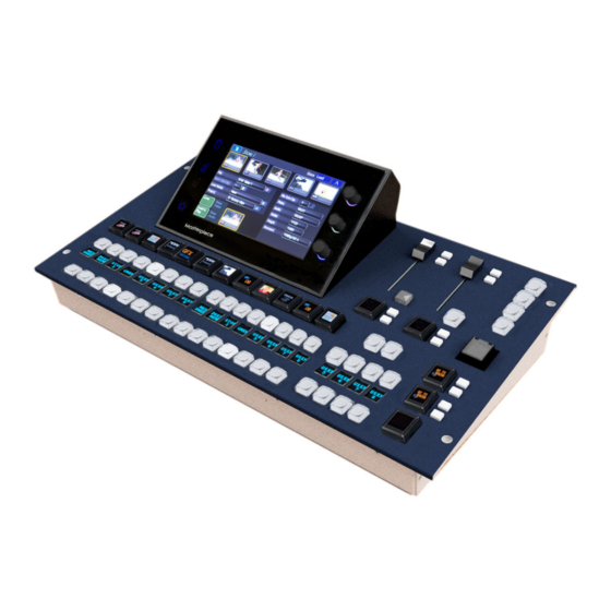
Page 49: Control Surface
The Control Surface The layout of the Masterpiece Control Surfaces is best explained by breaking down the control surface into sections. Moving around the control surface counter clockwise in the diagram below, each numbered item will be explained in this section of the manual. -
Page 50: Source Selection Crosspoint Buttons And Colored Mnemonics
Source Selection Crosspoint Buttons and Colored Mnemonics Source Selection Crosspoint Buttons and Colored Mnemonics The Masterpiece Control Surfaces has two rows of source selection buttons, the top being the Program selection buttons and the lower being the Preview buttons (PGM/PVW). -
Page 51: Mnemonics
User Manual Mnemonics Mnemonics on Masterpiece display the name or icon assigned to the source that is set for that crosspoint button. The mnemonics can be set to display either text or a basic image, this is done in the Crosspoint menu and will be explained in the Crosspoint section of this manual. -
Page 52: Take Next
Touch the OLED button to select the required transition time. Touch the OLED button a second time and the Video Transition parameter menu will be displayed on the Masterpiece control surface GUI. Here you can set up a user defined transition time. -
Page 53: Ftb/Ats
Masterpiece User Manual FTB/ATS This is the Fade to Black/Audio to Silence (FTB/ATS) button. The button is protected with a flip up lid to stop anyone accidentally pressing the button. When pressed, the button will flash red and any video source going live to air will go black and any audio source going live to air will be silenced. -
Page 54: Assignable Motorized Faders
The Audio Faders are assigned to an audio function using the toggle buttons and OLED buttons below the faders. Once assigned, the faders will directly work with the on-screen faders on the Masterpiece control surface GUI. The “Normalize” button when pressed, will automatically move the slider back to the default setting. -
Page 55: Touch Screen Graphical User Interface (Gui)
Masterpiece User Manual Touch Screen Graphical User Interface (GUI) The touch screen GUI allows you to setup audio levels, audio and video transitions, setup stores and Key Layers. Setup and Configuration is done using the external GUI. - Page 56 Control Surface Source Selection Crosspoint Buttons and Colored Mnemonics...
-
Page 57: Masterpiece Menu Operation
Masterpiece Menu Operation The Graphical User Interface Masterpiece is controlled using two different GUIs. The GUI on the masterpiece control surface is mainly used for monitoring and operational tasks, such as; Audio Controls, Audio and Video transitions, Key selection and control and Store selection. -
Page 58: Touch Screen Monitor Menu Overview
The Graphical User Interface Touch Screen Monitor Menu Overview Configuration and setup of a Masterpiece system is driven using the intuitive menu system on the touch screen or mouse pointer driven Graphical User Interface (GUI). The type of GUI monitor used is a customer selected option, but the menu structures will be identical. -
Page 59: Gui Menu Layout Overview
Masterpiece User Manual GUI Menu Layout Overview Setup, Effects and System Configuration menu selection is done using the buttons down the left side of the menu. Parameter controllers are on the right side of the menu and consist of on- screen rotary controls and sliders (these can be attached to the physical rotary controls and joystick on the control surface). -
Page 60: Menu Selection Buttons
Masterpiece Menu Operation GUI Menu Layout Overview Menu Selection Buttons The information below highlights the function of each button. Mixer Setup: Mixer Setup These buttons are used to setup the Key Control Actions for Keys 1 to 4 Full, Linear, Luma and DVE setup. - Page 61 The Copy Clone and Paste Clone buttons are used to copy button functions from either the Paste Clone Masterpiece menus or from the control surface and allows the user to setup a system to their own operational preference. Copy & Paste The Copy &...
- Page 62 {Enter} button. The details are slightly different, depending on the GUI: • On the Masterpiece control surface GUI, touch the “Star” button to show the 'Star pop-up' . Use the “Direct Menu Jump” keypad to enter the menu number. The number is shown on the “Enter”...
- Page 63 Masterpiece User Manual Disable Tracking Off Disable Tracking On Disable Tracking Disable Tracking - This is a one button press to disable all the tracking elements set in the “Panel Config-Preferences - Tracking Preferences” menu. When selected, Menu Tracking, Store Tracking, Layout Tracking, Mixer &...
-
Page 64: Using The Gui Menus
Masterpiece Menu Operation Using the GUI Menus Using the GUI Menus 1. Title Bar 2. On-screen Rotary and Slider Controls and Integer Buttons 3. Attachers with Parameters Title Bar All menus have a title bar situated at the top of the menu, the title bar Shows the full title of the current menu. -
Page 65: On Screen Control
Other Menu Functions Masterpiece GUI Menu Link Buttons Menu Link buttons allow the user to enter a sub-menu, mainly shown at the bottom of menu’s. -
Page 66: Time And Timecode Adjustments
Masterpiece Menu Operation Using the GUI Menus When pressed the Action buttons apply the selected action to a menu. The buttons go Green when active. Menu Link Buttons Action Buttons Masterpiece GUI Popup Selector Pop-up List Popup - Touching this button will display an “options dialog box”. This allows the user quick... -
Page 67: On-Screen Qwerty Keyboard
Masterpiece User Manual On-Screen QWERTY Keyboard Some menus have name attachers, touching the red oblong twice will display an on-screen QWERTY keyboard that can be used to enter text. Enter the chosen name (text entry is displayed at the top of the keyboard dialog box), then press “Enter”. -
Page 68: The Masterpiece Gui
Masterpiece Menu Operation The Masterpiece GUI The Masterpiece GUI The Masterpiece GUI is part of the physical control surface, it is mainly used for monitoring the status of the of Masterpiece; Key layers, Program/Preview outputs and Audio/Video transition setup Title Bar... -
Page 69: Status Alert Triangle
Masterpiece User Manual Status Alert Triangle An “Status Alert Triangle” may be displayed in the information bar, as shown below. This is to alert the user to a possible problem that may have occurred. Status Alert Triangle Touch the triangle and a “Status Alert” dialog box will appear. An alert message will be displayed in the center of the dialog box menu. -
Page 70: Delegates Menu Button
Masterpiece Menu Operation The Masterpiece GUI Delegates Menu Button If the user touches the blue Delegate button at the top of a menu, then a Delegates menu will appear (in some menus) over the current menu. The Delegates menu gives the user selection options. -
Page 71: Touch Screen Menu Area
Masterpiece User Manual Touch Screen Menu Area This is the menu selection area (marked in red in the menu below), where the user selects which menu they require, turns functions On/Off, adjusts parameter controls or steps through to sub menus. -
Page 72: How To Use Copy And Paste
Masterpiece GUI (shown below left), or press the {COPY CLONE} button on the Touch screen GUI (shown below right). The buttons will flash until the “Paste” button on the Masterpiece GUI is pressed or the {PASTE CLONE} button is pressed, once again the buttons will flash. A dialog box will be displayed on the Touch screen GUI with a selection of Lamp options. - Page 73 Masterpiece User Manual Soft GUI Control Panel & GUI Prefs Virtual Keyboard...
-
Page 74: Masterpiece Gui Menu Controls And Buttons
Masterpiece GUI Menu Controls and Buttons Masterpiece GUI Menu Controls and Buttons Buttons and controls within the Masterpiece GUI menus have to be explained, so the user is immediately aware of the state of a menu at a glance. The way the colored buttons and attachers behave are all very important in understanding how to control and adjust functionality of Masterpiece. - Page 75 Masterpiece User Manual Action Buttons Action buttons are brown color. When and action button is touched (selected), the button will turn and orange/yellow color. Toggle Buttons Toggle buttons will toggle On then straight away go Off when touched. The border around the button will light up a bright green color, and stay lit until the users finger is taken off the button.
- Page 76 When a menu has parameters with colored attachers, it shows that a parameter can be adjusted using the rotary controls on the right side of the Masterpiece GUI. On entry to a menu, if the menu has only 1 colored attacher, it will be lit the Grass Valleye color as the top rotary control, if there are 3 or more colored attachers the top 3 will be lit the Grass Valleye color as the 3 rotary controls to show that they can be adjusted.
-
Page 77: Numeric Keypad
Masterpiece User Manual Snap - when pressed, notice that the parameter has jumped to an incremental value, normally in steps of five or ten. The border of the button will turn red Normal - when pressed, the parameter will revert back to its original default state, the border of the button will once again turn Green. - Page 78 Some menus are longer in length (have more parameters) than others, this means that the bottom of the menu will be below the viewing area of the Masterpiece GUI screen. Place a finger on a parameter and hold, whilst holding, scroll upwards, the menus can be “flicked”...
-
Page 79: How To Save
How to Save Saving Files Masterpiece is a very flexible system and gives you a number of options to Save. There are Switcher States, Rolling Switcher States, Effects Memory Recalls, individual Configuration Files and Snapshots. This sounds like a lot of options, but how they are applied will depend on what you want to do with the system. -
Page 80: Rolling Switcher States
How to Save Switcher States This is done by pressing the {Overwrite} button. The date and time that the Switcher State was saved (overwritten) is displayed in the list. By touching the boxed area next to the time and date, a name can be given to the Switcher State using an on-screen keyboard. Touch {Load} button to load the saved Switcher State. -
Page 81: Config Files - Saving And Loading
Masterpiece User Manual Config Files - Saving and Loading The User, Panel and Engineering Config files are very important when setting up a system and should be saved regularly so that your configuration state is not lost. User, Panel and Engineering Configs can have up to 1000 different config setup states each. - Page 82 How to Save Switcher States save to. If you touch the {Save As...} button when an existing saved config file is selected, a dialog will be displayed asking the you if you want to proceed to save the file. Loading a Config File To load a config file, simply select a file by touching it in the config file table and then touch the {Load} button.
-
Page 83: Snapshots
Masterpiece User Manual Snapshots Snapshots as the name suggests will take a snapshot save of the current system setup. They are applied to one of the OLED buttons on the control surface and once they are saved, they are an instant recall of the saved system setup. -
Page 84: Detaching Snapshots
How to Save Snapshots Detaching Snapshots Snapshots are attached to the OLED buttons when saved, you can detach a snapshot from an OLED button, so that a new snapshot can be saved. This is done in the “Panel Config - Button Info”... -
Page 85: Dmem's
Masterpiece User Manual DMEM’s What is a DMEM A DMEM or Dynamic Memory, saves set-up information related to a single system setup, which may contain information such as: • Bus set-up (Crosspoints, Keyers, Wipes, Transitions) • Macros • DVE moves •... - Page 86 How to Save DMEM’s The next step is to select the required enables. You can do this by either touching each required enable option (it will turn green when selected) or you have the option to copy enables from the current file and save them to a new file or to overwrite the existing file using the {Copy File Enables} button.
-
Page 87: Number Pad
Masterpiece User Manual Last Loaded Touch the {Last Loaded} button to display last loaded memories information. The popup menu displays the information from the last loaded memory file. Number Pad Touch the {Number Pad...} button to display the Number Pad menu. To save a DMEM using the “Number Pad”... - Page 88 How to Save DMEM’s When saving a new DMEM, look in the “Filing System - DMEM” menu, so that you can select a DMEM file number that is free. Go back to the “Shortcuts” menu and enter the DMEM file number, then select what you want to save within the DMEM;...
-
Page 89: Enables
Masterpiece User Manual Enables In the Shortcuts menu, you are able to select or de-select the enables functions within a DMEM. Mixer Enables menu. Touch the “Sub-Enables” menu to select/de-select the Mixer Sub-Enables User Enables menu. If the tab next to the... - Page 90 How to Save DMEM’s...
-
Page 91: Video Setup
Video Setup System Setup This chapter is a guide to getting external and internal video sources through a Masterpiece mainframe quickly. A good place to start is to decide what video format you want; either HD or UHD. In the “Connected To...”... - Page 92 Video Setup System Setup In the “Mainframe Configuration” menu, you can select which “Video Type” you want to use; SD/ HD or UHD. Touch the {Up} button to go back to the “Connect” menu then touch the {Switcher login} button to log back into the system. The next section in this chapter will describe how to get a video signal through the system in SD / HD.
-
Page 93: System Config
Masterpiece User Manual System Config In the “Eng-Config” menu, touch the {System Config...} menu link button to enter the “System Configuration” menu. Using the “New Standard” parameter, scroll through the video standards and set the required System Standard, then touch the {Apply} button. -
Page 94: Inputs And Naming
Video Setup Inputs and Naming Inputs and Naming Signals to the system can be connected to one of the 40 available inputs on the mainframe. Touch the {Eng Config} button, then touch the {Input Setup...} menu link button. Touch the “Name” attacher and give all the incoming sources a name for easy identification. Outputs and Naming In the “Eng Config”... -
Page 95: Aux Buses
Masterpiece User Manual Aux Buses Touch the {Aux Buses} menu link button. Aux Bus 1 to 14 are the Grass Valleye as Outputs 1 to 14 (HD video format only) at the rear of the mainframe. This menu is used to set the sources going to each output. -
Page 96: Button Maps
“Button Map Assignment” menu will now be displayed. Button mapping allows you to map external and internal sources to the crosspoint buttons on the masterpiece control surface. Button maps are easy to setup and are the preferred way to setup crosspoints on a control surface. - Page 97 Masterpiece User Manual Once the “Save to File” button has been touched, the menu will change back to the “Button Map Assignment” menu. The saved button map will be displayed in the table at the top of the menu, and also displayed as “Mixer Bank A”...
-
Page 98: User Config - Mixer Outputs
User Config - Mixer Outputs User Config - Mixer Outputs Masterpiece has a maximum of 3x Mixer outputs, all of which are programmable. This means that you are not restricted and can assign any one of the outputs to be an Mixer outputs. All Mixer outputs are programmable which means that the outputs can be configured and their states changed;... -
Page 99: Audio Setup
Below is a simple block diagram of the audio paths through masterpiece. The AES In channels 1 to 4 and AES Out channels 1 to 4 are input and output via the 25Way AES/LTC connector at the back of the Masterpiece mainframe. -
Page 100: Getting Audio Into Masterpiece
• 25 Way AES/LTC audio connector at the rear of the mainframe In most cases audio will be input into Masterpiece via the SDI inputs in the form of 16 channel AES audio and mixed with audio from the Clipstore or voice over. -
Page 101: Audio Shuffler
Masterpiece User Manual Audio Shuffler The Audio Shuffler matrix allows you to build up to 50 audio shuffle profiles using the 16 channel AES audio matrix map (shown in the menu below). The shuffle profiles can be assigned to Crosspoints (XPT) in the XPT main menu or the AES Inputs 1 to 4 in the Audio Shuffle menu. -
Page 102: How To Build A Shuffle Profile
Audio Setup Audio Shuffler How to Build a Shuffle Profile To build a shuffle profile, turn “Enable” and “Allow Mix” On, (allowing mixing will give you the option to mix multiple inputs to the Grass Valleye output. It has the effect of summing the signals together). - Page 103 Masterpiece User Manual The menu below displays an audio shuffle on input channels 1 & 2 and 3 & 4. Their default state was Inputs 1 & 2 to outputs 1 & 2 and Inputs 3 & 4 to Outputs 3 & 4.
- Page 104 Audio Setup Audio Shuffler You can also assign Shuffle profiles to crosspoint sources on the Masterpiece GUI. In the home menu, below the Program and Preset audio level meters, the current crosspoint source is displayed (highlighted below). If you touch the crosspoint source menu link button, a “Crosspoint Shuffle”...
-
Page 105: Understanding The Masterpiece Gui Audio Menus
This menu displays a more detailed menu with “soft” audio faders that can be assigned to the physical faders on the Masterpiece control surface. You can see which soft fader controls are currently assigned to the control surface by using the toggle buttons to scroll through the assigned function list. - Page 106 Audio Setup Understanding the Masterpiece GUI Audio Menus When the soft fader is moved up/down if the audio function is selected on the OLED button, the physical fader on the control surface will move in unison with the soft slider. As you move the fader on the control surface, notice that the fader level information is displayed in the menu.
-
Page 107: Masterpiece Gui Audio Menus
Masterpiece User Manual Masterpiece GUI Audio Menus The diagram below displays all the available audio function menus. -
Page 108: Using Masterpiece Gui Audio Menus
The Program Preset and Main Out audio menus are the most critical to the to the output of Masterpiece as these control the audio that is going live to air and the audio that will be going live to air next. With a Button Maps created and the Crosspoints set up on the Masterpiece control surface, the audio menus on the Masterpiece GUI can now be used. -
Page 109: Preset Audio
Masterpiece User Manual Touching the menu expander will open the settings dialog box. Touch the {Assign} button, the button will light up “light blue” (as shown below). The function will be displayed when scrolling through the function list. To enable the function touch the OLED button. - Page 110 Audio Setup Using Masterpiece GUI Audio Menus Buttons: Trans - selection will push the Preset Audio into the main audio transition Reset - resets the fader to 0dB (can be overridden by Morpheus automation) Take - selection will push the Preset Audio to transition when the [Take Next] button is pressed.
-
Page 111: Main Out Audio
User Manual Main Out Audio Main Out, this is the main audio output from Masterpiece and controls the audio level for the program output. By default, the audio level is set to 0dB and any adjustments using the audio fader will reduce the audio output from Masterpiece. -
Page 112: Stores (Internal Audio Source)
Audio Setup Using Masterpiece GUI Audio Menus Stores (internal audio source) Stores provide an internal audio source via the “Clipstore” function. Clipstores are pre- configures clips of either just audio or audio with a bug/video clip. There are 10 internal stores that can be used as a source to a crosspoint or provide a source for a squeeze back macro. -
Page 113: Util Audio
Masterpiece User Manual Util Audio This adjusts the audio for sources assigned to the Utility Bus. The audio is routed from one of the 16 AES stereo pairs from either the SDI inputs or the AES inputs from 25 Way AES/LTC connector. -
Page 114: Voice Over Audio
Audio Setup Using Masterpiece GUI Audio Menus Voice Over Audio The voice over channel is actually a group channel, where by a number of input channels can be assigned to the group (voice over). As shown below the Inputs available for assignment are AES 1, AES 2, AES 3, AES 4, STORE and UTIL. - Page 115 Masterpiece User Manual Note: The Cut - On lamp behavior is determined from Panel Config - Preferences- Audio Mixer Lamp Mode. The Voice Over “Prefade Metering” displays the voice over metering before the voice over attenuation level has been applied.
-
Page 116: Aes In Audio (1 To 4)
Audio Setup Using Masterpiece GUI Audio Menus AES In Audio (1 to 4) The four AES Input stereo pairs are routed from the 25 Way AES/LTC connector, they are inputs 1&2, 3&4, 5&6 and 7&8. Each fader controls an AES Input (channel pair 1 & 2) level providing some gain +10dB and attenuation (0dB to -Inf ). -
Page 117: 25 Way Aes/Ltc Connector In/Out Pin Configuration
The In/Outputs display the “Shuffle” for 16 channels of AES, the profile displayed is for AES In 1. 25 Way AES/LTC Connector In/Out Pin Configuration The diagrams below display the single 25 Way D-type AES/LTC connector at the rear of the Masterpiece mainframe and the pin-out configuration with signal information for each pin. Pin 13 Pin 1... -
Page 118: Audio Monitoring
Audio Setup Audio Monitoring Audio Monitoring Preview Audio Preview Audio allows you to listen to any of the audio input stages as well as the Main Out stage before the audio is used. You can select the audio that you want to preview by touching one of the “Monitor”... -
Page 119: Aes Audio Out 1 To 4
Masterpiece User Manual AES Audio Out 1 to 4 The AES Audio Out 1 to 4 menus are used to monitor any of the input stages including the Main output stage. Each menu does the Grass Valleye function for its AES output The Monitor Channel are used to select the 2 audio outputs, AES outputs are limited to 2 output channels and allows you to monitor any of the 16 channels into the audio mixer. -
Page 120: Audio Transitions
Before starting to use the Transition menus, make sure that the [AUDIO TRANS] button is selected and illuminated light blue. The main menu on the Masterpiece GUI is basically spit in half horizontally, the bottom half is deals video functionality and the top half is audio. Touch the yellow button above the {Audio... -
Page 121: Audio Transition Menu
Masterpiece User Manual Audio Transition Menu In the Audio Transition menu you can setup the type of transition you want for the audio. Touch one of the Transition Type buttons (the button will turn yellow when selected) at the top of the menu to set the type of transition you require. - Page 122 Audio Setup Audio Transitions Like the “Key Layer” buttons, when the “On” button is illuminated, the audio source of the selected function will contribute to the on air output. If the “Tr” button is illuminated and the “On” button is not illuminated, when the “Take Next” button is pressed, the source will transition on air with the Preset audio source going to Program on air.
- Page 123 Audio transitions will now transition at the new set time. If the “In Trans” Buttons; at the bottom of the audio faders on the Masterpiece control surface are selected, when a “Take Next” transition is made, the faders will move to reflect the selected Audio Transition Type.
- Page 124 Audio Setup Audio Transitions...
-
Page 125: Engineering, User & Panel Configuration
Engineering, User & Panel Configuration Saving Files Before describing the Configuration menus, it is a good idea to explain how to save a config file. Saving a Config File The Engineering, User and Panel Config files are used to save up to 1000 different config setup files. -
Page 126: Sub Enables
Engineering, User & Panel Configuration Saving a Config File Sub Enables The “Sub Enables” list of buttons, to the right of the config files table, allows the user to select or de-select functions that can be saved with a file. If the tab next to the enables button is green, this means that the function was included when the file was originally saved. -
Page 127: How To Save A Config
Masterpiece User Manual How to save a Config In the User Config main menu, press the {Save As} button and a new config file table will be displayed. In the table, select a slot where the file will be saved using the “Destination”... -
Page 128: Engineering Configuration
Engineering, User & Panel Configuration Engineering Configuration Engineering Configuration To get to the {Eng Config} button to open the “Engineering Configuration” menu. In this menu you can setup the Inputs, Outputs and System Standard which are the main setup. Input Setup The Input Setup menu has several main configuration functions integrated into one to allow the user to quickly configure an input to the mainframe. - Page 129 Masterpiece User Manual Parameter Controls The Name attacher allows the user to give the selected input a name and a description; using the on-screen keyboard. The Router Overwrite parameter when set to {Yes} will allow an externally connected router to rename a source.
- Page 130 Engineering, User & Panel Configuration Input Setup The “Timing” parameter indicates the Offset in Micro seconds (or Milli Seconds) between the Reference input and the selected source. To Clean switch or avoid a Line offset (e.g. a vertical shift) the Timing has to be within +/- half a line of the current standard. e.g. for 1920x1080i59.94 +/-14uS).
-
Page 131: Output Setup
Masterpiece User Manual Output Setup This menu is where each BNC output from the Masterpiece mainframe is setup, within these menus the user is able to: • Setup 12G-SDI operation • Name and give a Description to each BNC output •... - Page 132 HANC/VANC - Ancillary Data can be output from any BNC output on the mainframe. These buttons are used to either pass or block the ancillary data on each individual output. The Masterpiece is able to receive Ancillary Data and pass the ancillary data out from any BNC outputs from the mainframe.
- Page 133 Masterpiece User Manual Note: The menu below displays a system setup in UHD mode. UHD Output - Like the UHD Inputs, when UHD is selected in the “Mainframe Configuration” (in the Logged Off state), selecting UHD Output “On” will tie Outputs 1 to 4 together. There will be 4x Outputs for every UHD source input to the mainframe, which consist of Output 1 (top left), Output 2 (top right), Output 3 (bottom left) and Outputs 4 (bottom right).
- Page 134 Engineering, User & Panel Configuration Output Setup Output Tally The GPO Tallies can be set to provide up to 8 further output Tallies ISO1 to ISO8. These can be used to Tally outputs that are being used as ISO (isolation) Feeds. Tally Now sets the tally for the on-air Sources (red).
-
Page 135: System Standard
System Standard The system standard menu; as the name suggests, is where the default video standard is set for the Masterpiece system. The system standard is set to a default, to change the standard use the “New Standard” parameter to scroll up/down through the list of video standards. When the required standard is reached, notice the {Apply Standard} button has turned orange, press the “Apply Standard”... -
Page 136: System Standard - Uhd Mode
Touching the {Mainframe Config} button will open the “Mainframe Configuration” menu. Touch the {UHD} button to select UHD mode, then press the {Up} button to go back to the “Connect” menu, then touch the {Switcher Login} button to log back into the Masterpiece operational menus. -
Page 137: Gpo
User Manual This is a “source” based GPO setup menu, meaning that it is used to tally on sources coming into the Masterpiece mainframe. GPI/O Select is used to scroll down the table through the individual GPI/O/Tally’s, the Name parameter allows the user to re-name the tally if required. The default table is a one-to-one connection;... -
Page 138: Ip Gateways
Engineering, User & Panel Configuration IP Gateways IP Gateways The Engineering Config - IP Gateway menu allows the user to add a route to a destination network through a local IP Gateway. Touch the IP Address of Gateway attacher and set the four New Gateway parts of the address (A) (e.g. -
Page 139: Protocols
Masterpiece User Manual Protocols The Protocols menu is used to set parameters for bi-directional communication with external devices either by one of the RJ45 RS422 ports or selecting one of the IP protocol connections. Protocols have to be setup in this menu before the Peripherals functions can be used. - Page 140 Engineering, User & Panel Configuration Protocols After the Load button was touched, the selected protocol is placed in the Loaded Protocols table, touch the {Configure} button to enter the Protocol Config menu. The user is able to select the type of connection that is required “Transport Type” i.e Serial or IP, and also set user-defined parameters for the protocol.
- Page 141 Masterpiece User Manual The {Activate} button will be yellow, if happy with the setup, touch the {Activate} button. The protocol setup information is displayed on the right side of the menu.
-
Page 142: Status Monitor
Status Monitor The Status Monitor function monitors the overall health of the mainframe allowing the user to easily see any problems in the unlikely event that the Masterpiece mainframe should have a fault. The main status monitor menu displays all the internal cards in the mainframe, the power supplies, fans and Rear Cards. -
Page 143: Panel
The Status Monitor - Panel menu allows the user to monitor the CPU temperature in the control surface. The user is also able to setup the SysLog Server IP address so that an external PC running SysLog Server software can monitor Masterpiece. (please read the next section of this manual). -
Page 144: Status Monitor Panel - Syslog Server
In the unlikely event of there being a problem with a Masterpiece system, Syslog can be used to display error log files. Connection To use Syslog, a computer needs to be connected to the Masterpiece mainframe via one of the network ports (as shown below). IP address The next thing to find out is the IP address of the computer being used. - Page 145 Masterpiece User Manual Masterpiece Setup The next, setup the connection between the computer and the Masterpiece mainframe. Touch the {ENG CONFIG} menu link button, then touch the {Status Monitor...} menu link button. Then in the “Status Monitor” main menu touch {Panel} menu link button where the SysLog...
-
Page 146: Syslog Application
Engineering, User & Panel Configuration Status Monitor Touch the {Edit IP Address}, then enter the IP address of the computer. In the menu, use the “IP Port” parameter to set the port number. It is set to “514” as a default, but it can be changed to a user defined number. - Page 147 Note: Usually, Syslog servers will use UDP port #514, although they will offer the ability to change this port, allowing the Grass Valleye machine to run multiple Syslog servers simultaneously. Click on {OK} and the Syslog software should now start receiving messages from Masterpiece.
-
Page 148: Setup Menu
The job of a Syslog server is to open up a network port and log all Syslog format messages that are received at the port; in this example from Masterpiece. Usually, messages are recorded continuously into a file or files on the disk. - Page 149 Masterpiece User Manual Messages The Status Monitor - Message History menu will display a history of any significant events or hardware warnings with the time and date against them. In the unlikely event of a problem, this menu can be used as a high level review of any possible failures.
-
Page 150: Formatfusion3Tm
Engineering, User & Panel Configuration FormatFusion3TM FormatFusion3 The FormatFusion3 parameters allow the user to control or change the aspect of an input source, or crop an oversized source. FormatFusion3 would mainly be used to convert a HD source to a UHD source. Input FormatFusion3 Inputs and Channels To use FormatFusion3, touch the {Input Setup...} button, then in the menu, select an input by touching an input row or use the “BNC Input”... - Page 151 Masterpiece User Manual Source Input Setup Source - This selects the BNC Input. Use Default Standard - This parameter will force the input source to use the default mainframe video standard which is set in the Eng Config - System Standard menu. The Default Standard can be changed using the New Standard parameter, use the Up/Down scroll buttons to select the required standard, then touch the {Apply} button.
- Page 152 Engineering, User & Panel Configuration FormatFusion3TM artifacts appearing at cut points. Film Pair is used when creating the current field/frame, will directly combine the current input field and either the previous or next field. This mode should only be used if the fields are temporarily matched, e.g.
- Page 153 Masterpiece User Manual in this setting a letter box effect is seen where there are bars at the top and bottom of the image. The Full Height parameter will change the aspect so that the full height of the 16:9 aspect ratio is filled, leaving bars either side of the image.
-
Page 154: Color Correction
Engineering, User & Panel Configuration FormatFusion3TM Color Correction Input FormatFusion3 color correction allows the user to color correct a selected Channel/Input. To use Color Correction, turn “On” the Color Correction parameter and touch the {Color Correction...} menu link button. In the Color Effects menu, make sure that the “Color Fx” button is selected, from here the user can select the type of color correction required. - Page 155 Masterpiece User Manual Touch the {YUV} button to enable the parameter controls. Touch the YUV Control attacher and by changing the parameters, the Brightness, Contrast and Saturation of the channel can be adjusted. • Brightness default value is 0.00%, and the range is from -10% to 100% •...
- Page 156 Engineering, User & Panel Configuration FormatFusion3TM Touch the “RGB” button to enable the parameter controls. The initial menu is set to a default condition, which Shows the Master adjustment parameters. This will give an adjustment of Master Lift, Gain and Gamma. Each of these adjustments will alter all three elements of the RGB signal at the Grass Valleye time.
- Page 157 Masterpiece User Manual Presets Presets allow the user to quickly select commonly used preset color options for the crosspoint source, or quickly revert back to the original input source color levels. Normal - Is the original color levels of the input source; without any color correction adjustments.
- Page 158 Engineering, User & Panel Configuration FormatFusion3TM Curves The Curves function is used to artistic type effect to the selected FormatFusion3 channel. The user can select preset effects such as Solarize and Posterize, and then adjust them to give a user-defined effect. The user can select from 6 Preset Curve options by touching the button or use the Type parameter to select from a list of options.
-
Page 159: User Configuration
Masterpiece User Manual User Configuration Mixer Outputs Masterpiece has 3 fixed Outputs, Mixer Op1, Mixer Op2 and Mixer Op3. For ease of use, the outputs should be setup as follows: • Mixer Op1 - Program Out • Mixer Op2 - Preset Out •... -
Page 160: Fade To Black
Engineering, User & Panel Configuration Mixer Outputs Fade To Black The Fade To Black function is normally needed when a live broadcast has a problem, it would be used to take the program output to “Black”. To use fade to black, enable FTB by selecting Fade To Black - “Pgm”. The above parameter controls alter the FTB profile and transition timing. -
Page 161: Store Setup
Masterpiece User Manual Store Setup The Store Setup menu allows the user to setup the way the Stores are coupled when using a clip. The allocation of time to each Store can also be setup in this menu and the Stores can also be given names. - Page 162 Engineering, User & Panel Configuration Store Setup Store 9 is coupled to KStore 10, as can be seen in the minipics 9 and 10. Linked To Store - this will display any Stores that are linked to each other. Store Name - this is the user-defined name given to a Store, using the “Store Name” parameter. Audio in Reverse - to select “Audio In Reverse”, select a Store in the table and then touch the {Audio In Reverse} button.
-
Page 163: Gpo Setup
Masterpiece User Manual GPO Setup This GPO Setup menu is used to tally Crosspoint based, Bus based and User BIT functions. The default setup state allows the user to tally GPO’s 121 to 256 which are the physical and internal GPO’s and are comprised of: GPO 121 to GPO 132 and GPO 133 to GPO 144 are the physical Ref Fin GPO’s, again at the rear... -
Page 164: Crosspoint Options
Engineering, User & Panel Configuration GPO Setup Crosspoint Options When selecting the type of GPO or GPI trigger, as mentioned previously, press the popup attacher to easily access the other Crosspoint options. -
Page 165: Modulation
Masterpiece User Manual Modulation Overview The modulation function enables the user to add modulation effects to transitions, wipes, borders and DVE. The type of modulation applied to a function is selectable and can be added to many different parameters, whether it is Global, Bus, I/O, DVE or User related. - Page 166 Engineering, User & Panel Configuration Modulation Phase - changes the phase of the modulation, range 360° plus complete turns, i.e. 5:180° this is 5 complete turns plus 180°. An individual modulator setup can be switched On, by selecting an individual modulation using the Modulator parameter.
-
Page 167: Bus Config Group
Masterpiece User Manual The modulator Gain can be used to adjust how much effect the transition engine has on the modulated parameter. Global Modulators as well as Bus and User Config group modulators can all use the Transition type modulator. -
Page 168: Mixer Trans Group
Engineering, User & Panel Configuration Modulation All Start/ALL STOP - as described on the previous page, this function will set all the modulation setups in the table to run or stop. Detach - this will delete a selected modulation setup in the table. Mixer Trans Group These are modulators set to work with function in the Mixer Transition menu. -
Page 169: User Config Group
Masterpiece User Manual User Config Group The menu below works in exactly the Grass Valleye way as the Bus Config Group. They all have a “Local” type modulation setup or can be attached to a Global Modulations setup. The User Config Group modulators are attached to parameters within the User Config menus;... -
Page 170: Basic How To Use Modulators
Engineering, User & Panel Configuration Modulation Basic How to Use Modulators How to Use the Modulator Function The setup sequence will follow these easy steps: 1. Turn On Mod-Assign 2. Select the function the modulation is going to be attached to 3. - Page 171 Masterpiece User Manual Also notice that the attacher that displays the parameter settings has turned green as shown below. Once the [MOD ASSIGN] and [SNAP NORM] buttons are released the GUI display will jump to the assigned modulator menu and highlight the attached parameter function in the table and Parameter Function display box.
-
Page 172: Mattes
Engineering, User & Panel Configuration Mattes Mattes This menus allows you to adjust the color of the internal Mattes. The mattes can be used as internal sources for crosspoints, Transition Matte Mixes, Key Matte Fill and DVE Border Fill. The Matte colors in the above menu, represent the default matte colors. To adjust a matte, touch one of the matte colors and a set of parameters will be displayed. -
Page 173: Audio
User Manual Audio This menu allows you to select the type of metering you want to have on the Masterpiece control panel. Select the Loudness thresholds, and set the 6 ton generators Meter Type - select between AES/Digital (or what ever is set by the “Normal Meter Style”... -
Page 174: Preferences
Preferences Preferences menu allows the user to enable/disable functions on the GUI and Control Surface. Note: Panel and GUI Preferences can also be accessed on the Masterpiece GUI (information at the end of GUI and Panel Preferences in this section). - Page 175 Masterpiece User Manual Sub-Clip Active On Press - this will load a sub-clip into a Store when touched in the Store - Sub-clips menu. Touchscreen Click - when set to “On”, an audible click can he heard when touching the soft MLC GUI.
-
Page 176: Panel Preferences
Enable Macros - Enable Clones - Keyboard Brightness - this adjusts the brightness of all the buttons on the Masterpiece control surface. Legend Brightness - this adjusts the brightness of the mnemonic displays on the Masterpiece control surface. -
Page 177: Snapshot
Masterpiece User Manual Display Server Timeout - This causes the touch screen GUI to go into sleep mode after a designated amount of time. Default is 2 hours, maximum On time is 4 hours, can also be disabled so the GUI is on constantly. -
Page 178: Panel And Gui Preferences On The Masterpiece Gui
Preferences Panel and GUI Preferences on the Masterpiece GUI To get to the Panel and GUI Preferences touch the “Star” navigation button on the Masterpiece GUI and a sub menu will be displayed. Touch the Panel or GUI Prefs buttons to access the menus as shown above. -
Page 179: Button Maps
Masterpiece User Manual Button Maps Buttons on the Crosspoint Bus can have any source assigned to them using a Button Map. This can be done by saving and loading Button Map Files, or by creating Custom maps. Button Maps Main Menu The main menu allows you to load a button map file from the “Button Maps Files”... -
Page 180: Editing A Button Map
Engineering, User & Panel Configuration Button Maps Editing a Button Map Touch one of the {Edit} buttons to get to the “Panel Config - Edit Button Maps” menu. When the menu opens you can see that there are two tables, “Button” and “Source”, any changes made on this page will happen in real time on the Mixer buttons. - Page 181 Masterpiece User Manual • Shift - The button is now used to select between shift and un-shift for the whole bus of buttons. Traditionally this is placed at the far right of the bus. • Bus Lock - pushing this locks the operation of the entire bus. Pushing a second time cancels this.
-
Page 182: Button Information
Engineering, User & Panel Configuration Button Maps Button Information The Panel Config - Button Information main menu displays information about Clone button functions and Macro buttons. The Button Summary table displays all the information related to a selected button. Button Summary Button Name - the normal button function. -
Page 183: Button Functions
Masterpiece User Manual Button Functions These buttons are used to locate and disable Clones or Macros associated to a button. Live Mode - will turn Live Mode On or Off Stop All Macros - will stop all macros running Locate Button - this will allow the current function of any button to be summarized in the table. - Page 184 Engineering, User & Panel Configuration Button Maps Normal - switches the lamp between its normal Green color and the Red cloned color Macro - this will allow a lamp to be lit from a macro assignment Bitmap From Clone - displays a bitmap from the cloned function Macro/SS - by default, a User Function Button would be blank normally, however the button can also have a bitmap from a macro or snap shot.
-
Page 185: Mav Layout
MAV Layout The MAV Layout menu displays the control surface individual components connected together to make up the Masterpiece control surface. These are fixed and should not be altered or the control surfaces may not work correctly. Note: When the system has booted up, if the control surface doesn’t light up as expected, touch the {Masterpiece Auto Config} button to make sure that the Masterpiece control surfaces are configured properly. -
Page 186: Fader Maps
Engineering, User & Panel Configuration Fader Maps Fader Maps The Fader Map menu allows you to setup how the two faders work on the Masterpiece control surface. The menu can also be used to setup any external MAV-FADER modules connected to the control surface. -
Page 187: Panel Colors
The default color can be changed by adjusting the Hue and Saturation parameters. Other Colors The Other Colors menu allows the user to change the preset color scheme of the Masterpiece color crosspoint buttons. In the Crosspoint Mapping menu on the GUI, the user can select crosspoint in the table and then use the Xpt Lamp Color parameter to set a preset color scheme for the selected crosspoint. -
Page 188: By Standard Colors
Engineering, User & Panel Configuration Panel Colors The Other Colors menu allows the user to select and change the preset colors in the Color list. Touch one of the colors and then use the Hue and Saturation parameters to adjust to the desired color, then press the {Apply} button. -
Page 189: 12G-Sdi Setup And Operation
Masterpiece 12G-SDI offers 12G-SDI BNCs for UHD connectivity, as well as 3G BNCs for Quad link signals; HD sources are also available. Whilst using the Masterpiece mainframe in UHD mode, the user is now able to have a single link UHD input or output using the 12Gbps BNC connectors, the system does not have to have Quad link signals anymore. -
Page 190: Set The System Up In Uhd Mode
“Mainframe Configuration” menu, touch the {UHD} button to select UHD mode, then press the {Up} button to go back to the “Connect” menu. Finally, touch the {Switcher Login} button to log back into the Masterpiece operational menus. Note: Notice that when a touch screen GUI is connected to a Masterpiece 12G-SDI mainframe, the logo in the bottom left corner of the menu has “12G”... - Page 191 Masterpiece User Manual Once back in the “Connected to Masterpiece Mainframe” menu, the user has two choices when setting up UHD, either touch one of the preset UHD Shows at the top of the menu and UHD will be setup ready to use or the user can manually setup UHD by following the information through this section.
-
Page 192: 12G Sdi Input Setup
12G-SDI Setup and Operation Set the System up in UHD Mode 12G SDI Input Setup Touch the {Input Setup...} button, in this menu the user will setup all the UHD inputs to the mainframe. As stated at the start of this chapter, in UHD mode, there will be 4x inputs for every UHD source input to the mainframe, which consist of Input 1 (top left), Input 2 (top right), Input 3 (bottom left) and Input 4 (bottom right). -
Page 193: 12G-Sdi Output Setup
User Manual 12G-SDI Output Setup Setting up the UHD outputs on Masterpiece is very similar to setting up the inputs, where the outputs are grouped in fours. Touch the {Output Setup...} button and the menu will look like the one below. - Page 194 12G-SDI Setup and Operation Set the System up in UHD Mode...
-
Page 195: Ip Connectivity And Operation
Grass Valley, a Belden Brand, has a rich history in helping media organizations deliver content on time, on budget and to the right audience across whatever distribution mechanisms are appropriate. -
Page 196: Ip Architecture
IP Connectivity and Operation IP Architecture IP Architecture The physical media network link uses QSFP cages on the rear of the unit (‘Link A1’ . .. ‘Link B2’) and are 100G Ethernet links that are each configured for 2x 50G operation. When fitted, QSFP transceivers are internally connected to the Video IP blocks via a hard-wired network ‘cross- over’... -
Page 197: Ip Input Menus
Masterpiece User Manual IP Input Menus To get to the IP input menus, in the Input Setup menu, touch the {IP Setup...} menu link button. Ethernet Menu (above) At the top of the menu are the IPL Fin selection buttons. These buttons correspond to the IP inputs at the rear of the mainframe. - Page 198 IP Connectivity and Operation IP Input Menus Once the IP addresses are set, touch the {Apply All Interfaces & Restart Fin}, this has to be done to restart the IP Fin. Flow Menu The Flow menu allows you to setup each individual “Spigot” IP address, Source IP address. Each Flow needs to have a Multicast IP address and Port as well as the IP address and Port of the source.
- Page 199 Masterpiece User Manual The IP input Flow Template, allows the user to set the Multicast IP address (this is user specific). The Source IP is the IP address of the incoming source. When the information is input into the IP Input Flow Template, set the “Multicast Increment” to increment by “1”, the Template tool allows an address or port number to be incremented each...
- Page 200 IP Connectivity and Operation IP Input Menus Spigot Menu In the Spigot menu, the user is able to set the video standard for individual Spigots (inputs) using the “Format” parameter. By touching one of the Spigots, setting this parameter will allow more or less spigots to be used, depending on the type of format that is selected for the spigot.
- Page 201 Masterpiece User Manual Config Menu The Config menu only allows the user to change the current “DDS Domain ID”. Note: The software on the IP Input Fin has to be updated through RollCall directly to the IP Input FIN via the RJ45 Network port.
-
Page 202: Ip Output Menus
IP Connectivity and Operation IP Input Menus IP Output Menus To get to the IP Setup menus, go to the “Eng Config - Output Setup” menu and then touch the {IP Setup...} menu link button. Ethernet Menu (above) At the top of the menu are the IPL Fin selection buttons. These buttons correspond to the IP QSFP cages at the rear of the mainframe. - Page 203 Masterpiece User Manual If an existing IP address exists, the user can touch the {Copy to New} button and the IP address info will be copied across to the “New” IP address box. Once the IP addresses for the IP Output Fin are set, touch the {Apply All Interfaces & Restart}, this has to has to be done to restart the IP Output Fin.
- Page 204 IP Connectivity and Operation IP Input Menus The IP Output Flow Template allows the user to set the Multicast IP address (this is user specific). The Source IP is the IP address of the incoming source. When the information is input into the IP Output Flow Template, set the “Multicast Increment” to increment by “1”, the Template tool allows an address or port number to be incremented each time the {Paste from Template} button is touched.
- Page 205 Masterpiece User Manual Spigot Menu In the Spigot menu, the user is able to set the video standard for individual Spigots using the “Format” parameter. Setting this parameter will allow more or less spigots to be used, depending on the type of format that is selected for the spigot.
- Page 206 IP Connectivity and Operation IP Input Menus Config Menu The Config menu only allows the user to change the current “DDS Domain ID”. Note: The software on the IP Output Fin has to be updated through RollCall directly to the IP Output FIN via the RJ45 Network port.
-
Page 207: Uhd Setup And Operation
UHD graphics can be keyed over the full UHD screen. Connecting UHD to the Inputs and Outputs The first step to understand when using UHD with Masterpiece is how to correctly connect a UHD source to the inputs and outputs of the mainframe. -
Page 208: Uhd Initial Setup
Touching the {Mainframe Config} button will open the “Mainframe Configuration” menu. Touch the {UHD} button to select UHD mode, then press the {Up} button to go back to the “Connect” menu, then touch the {Switcher Login} button to log back into the Masterpiece operational menus. -
Page 209: Uhd Engineering Config Setup
Masterpiece User Manual UHD Engineering Config Setup In the Engineering Config main menu, touch the {System Standard...} button to enter the System Standard menu. The System Standard menu can be set to “UHD Mode - Quadrant” or “UHD Mode - 2SI”, however the user can choose between the UHD standards by touching the “Popup”... -
Page 210: Uhd Input Setup
UHD Setup and Operation UHD Initial Setup UHD Input Setup Touch the {Input Setup...} button, in this menu the user will setup all the UHD inputs to the mainframe. As stated at the start of this chapter, in UHD mode, there will be 4x inputs for every UHD source input to the mainframe, which consist of Input 1 (top left), Input 2 (top right), Input 3 (bottom left) and Input 4 (bottom right). -
Page 211: Uhd Output Setup
User Manual UHD Output Setup Setting up the UHD outputs on Masterpiece is very similar to setting up the inputs, where the outputs are grouped in fours. Touch the {Output Setup...} button and the menu will look like the one below. -
Page 212: Uhd Stores
UHD Setup and Operation UHD Initial Setup UHD Stores There are two UHD Stores and two 1080p Stores available to use in the Store menu in UHD mode. With the system set to UHD mode, touch the {Store} button to open the “Store - Load” menu. -
Page 213: Uhd Transitions And Wipes
User Manual UHD Transitions and Wipes Transitions and Wipes in UHD mode, works exactly the Grass Valleye way as using Masterpiece in any other video format. All of the wipe patterns, wipe controls, border fill and border position all work in exactly the Grass Valleye way. - Page 214 UHD Setup and Operation UHD Initial Setup...
-
Page 215: Keying And Dve Operation
Where one signal is used it both cuts and Fills the hole. This process of Keying with a single signal is known as a self Key or video Key. There are two types of Keying available with Masterpiece; they are Luma Keying and Linear Keying. -
Page 216: Accessing Keys On The Control Surface
Placing a Key Layer onto a Background The first step is to select a source for the Key. On the Masterpiece GUI, in the home menu, touch the Key (1 - 4) that you want to palace on the background. The Key Control sub menu will be displayed. - Page 217 Masterpiece User Manual In the example below, the source for the Key layer is selected from the Stores list and “Store 7” is selected. You can select sources form Crosspoints (Xpts), Mattes, Stores etc. As mentioned earlier, touch the bottom Key selection button and the Key layer is displayed on the Preset monitor, by default, the Key layer is full size over the background.
- Page 218 Keying and DVE Operation Placing a Key Layer onto a Background Then touch the {DVE Allocation...} button, which is towards the bottom of the menu. The “Keyer DVE Allocation” menu will open. In this menu, you can select which Key has DVE functionality applied. As the example in the menu shows, DVE-1 has Key 1 selected.
-
Page 219: Keyer Operation
Masterpiece User Manual Keyer Operation To get to the Keyer menus, touch one of the “Key” buttons {Key 1} (in this example) button in the top left corner of the menu.The “Mixer, Key 1” menu is displayed as shown below: Crosspoint - this parameter is used to select the source for the selected Key. -
Page 220: Using Keyer Control And Actions
Keying and DVE Operation Keyer Operation Using Keyer Control and Actions The type of Keying required is selected using the buttons below. Full - The Fill is a full layer over the background hiding it completely. Linear - Selects a Linear Key (see the first section of this chapter). Luma- Selects a Luma Key (see the first section of this chapter). -
Page 221: Keyer Functions On The Masterpiece Gui
You can setup a Key layer with many of the main parameters as explained in the previous section using the Keyer menus on the Masterpiece GUI In the home menu, touch one of the Key menu link buttons and the “Key Control” menu will be displayed. -
Page 222: Linear And Luma Keying
Gain - affects the sharpness of the lift point. Opacity - controls how transparent the Key is. Over Range - Masterpiece expects a video range Key of 64 to 940, the video range Key is used internally throughout the system. -
Page 223: Key Dve Operation
Masterpiece User Manual Key DVE Operation The DVE parameters allow the user to position and size a Key Layer, add a Border around a Key Layer or Crop a Key Layer. When enabled the DVE can be set to manipulate a Single or Dual Tile (which will be explained later in this section). -
Page 224: Position & Size
Keying and DVE Operation Key DVE Operation Position & Size Make sure that the DVE function “On”. The Position & Size attacher area, allows the you to move a Key Layer around the screen and to zoom in/out. X/Y Position - Parameters are used to move the position of the Key Layer around the monitor screen as shown below. -
Page 225: Crop
Masterpiece User Manual Zoom - Parameter is used to zoom the Key Layer in and out. Crop The crop menu as it suggests allows the user to crop the Key Layer, and also allows the user to apply soft edges. -
Page 226: Border
Keying and DVE Operation Key DVE Operation Border This function allows the user to apply a border and effects around a Key Layer. Border On/Off - Switches the Border On or Off Border Fill - Selects source for the border fill from a Matte selected using the Matte Selector parameters, Util 1 or Util 2 Border Width - Adjusts the overall width of the border Softness - Softens the outside edges of the border... -
Page 227: Dual Tile
Masterpiece User Manual Dual Tile This function allows you to take an existing Key Layer and create 2 Tiles (Key Layers) that can be independently resized (Zoom), moved along the XY axis, and cropped. The Dual Tile mode will now give: •... -
Page 228: Dual Tile Menu
Keying and DVE Operation Dual Tile Dual Tile Menu With a Key Layer on the monitor, make sure that the “DVE” parameter is turned “On” and then select “Tiles” Dual. Notice that the menu is split in two “Tile One” and “Tile Two”. Note: At this point you will only be able to see one tile, the other is underneath. -
Page 229: Tile 1 Crop
Masterpiece User Manual Zoom - Parameter is used to zoom the Key Layer in and out. Tile 1 Crop The crop menu as it suggests allows the user to crop the Key Layer, and also allows the user to apply soft edges. -
Page 230: Moving The Two Tiles So That Both Can Be Seen
Keying and DVE Operation Dual Tile Border Fill - Selects source for the border fill from a Matte selected using the Matte Selector parameters, Util 1/Util 2. Border Width - Adjusts the overall width of the border Softness - Softens the outside edges of the border The Matte Selector and Hue, Luma and Sat parameters are used to adjust the color of the border around a Key Layer when the option is selected in the Border Fill parameter. -
Page 231: Mixer And Transitions
Mixer and Transitions Types of Transition The three main types of transition that will be described in this section of the manual. These are: • Background Transitions • Key Transitions • Audio Transitions Setting Basic Transitions Independent transitions can be set for the Background, for each of the Key Layers. -
Page 232: Basic Background Mix Transition
Mixer and Transitions Types of Transition Basic Background Mix Transition On the control surface select one source on the Program Bus and a different source on the Preset Bus and make sure that the [VID TRANS] button is selected. Touch the {Mixer} button, then in the Transition menu, touch the {Background} button to enable the background for transitioning, select “Mix”... -
Page 233: Basic Key Transition
Masterpiece User Manual Basic Key Transitions Select the Key or Keys in the Transition or in the menu, then in the Transition menu, touch the {Mix} button and then press the [TAKE NEXT] button. Notice that the Key Layer will now transition over the A/B background. -
Page 234: Transition Control Button Functions
Transition Control Button Functions Transition Control Button Functions The main menu on the Masterpiece GUI is basically spit in half horizontally, the bottom half is deals video functionality and the top half is audio. Touch the yellow (shown in the menus... -
Page 235: Video Transition Menus On The Masterpiece Gui
Masterpiece User Manual Video Transition Menus on the Masterpiece GUI In the Video Transition menu you can setup the type of transition you want. Touch one of the Transition Type buttons (the button will turn yellow when selected) at the top of the menu to set the type of transition you require. - Page 236 Mixer and Transitions Transition Control Button Functions will go brown and the time in the box will increase/decrease. Touch the time attacher (it will turn yellow) and the “Transition Time” will change to reflect. Video transitions will now transition at the new set time. Wipe Parameter In the Video Transition menu, there are 10 quick select wipe patterns touch one of the wipe patterns, then when the [TAKE NEXT] button is pressed the selected wipe pattern will wipe...
- Page 237 Masterpiece User Manual Wipe Control Parameters Pattern - Adjust to select the required wipe pattern. There are a number of individual wipe patterns available. The number of available wipe patterns will vary depending on whether the background or Key is selected.
-
Page 238: Transition Parameters
Mixer and Transitions Transition Parameters When scrolling through the wipe patterns, notice the wipe pattern adjustment indicator box at the bottom of the wipe menu. When a wipe is selected this box will display parameters that denote how the wipe can be adjusted. Touch this box and a set of adjustment parameters will appear on the right of the menu. - Page 239 Masterpiece User Manual Shape - Selecting one of the Shape options will depict the type of profile curve; this will alter the acceleration rate for a transition. • Linear - constant transition, no change in transition acceleration • Cubic C and Sin C - these profiles are similar to each other, the default transition will have a fast acceleration at the start and slowdown towards the end.
- Page 240 Mixer and Transitions Transition Parameters Matte Selector - Select the required Matte from the options or Local Matte. Hue, Luma and Saturation will only affect the Local Matte setting. Matte Hue - sets the actual Matte color. The rotary control operates a 360 degree color wheel where: 0 = Red 60 = Magenta...
- Page 241 Masterpiece User Manual Aspect Ratio - Touch the On/Off button to activate the aspect ration function. As the name suggests, this function changes the aspect ratio of a wipe pattern, 0 to -100% will change the vertical ratio and 0 to +100% will adjust the horizontal ratio.
-
Page 242: Advanced Wipes
Mixer and Transitions Advanced Wipes Advanced Wipes The Advanced Wipe parameters offer additional wipe patterns that are created by combining the main wipe patterns. For example if a straight edge primary wipe is combined with a secondary circle wipe, the resulting wipe edge will now have a bowed effect, as shown in the example below. - Page 243 Masterpiece User Manual VFreq - controls the vertical frequency (number of peaks per centimeter) of the modulation VPhase - controls the start point of the of the modulation and thus the relative position of the peaks and troughs to the vertical edge of the wipe.
-
Page 244: Mix
Mixer and Transitions Advanced Wipes This allows a Background or a Key source to mix during a transition. Matte Mix Matte Mix Profile - The Matte Mix Profile is where the output passes through the Matte mix color between the two transition sources. This will cause the transition to go from the first source through a selected matte color to the second source. - Page 245 Masterpiece User Manual Fill - This function selects the type of source that will be used as a Matte. The options range from Matte, Util Bus 1 and 2. The Util Bus Fill is setup in the Util Bus menu. Touch the {Util/Misc} button on the GUI to see which crosspoint the Util Bus's are set to reference.
- Page 246 Mixer and Transitions Advanced Wipes...
-
Page 247: Effects Dissolve And Squeeze Effects
Effects Dissolve and Squeeze Effects Effects Dissolve Effects Dissolve gives you a means of creating a smooth transition from one memory state to another by interpolating any variable values (i.e. size, position, border width, etc.). Any state- change variables (e.g. button pushes) can be set to change at the start or end of the dissolve and provides a simple way of creating a two key-frame effect. -
Page 248: Saving An Effects Dissolve With A Dmem
Effects Dissolve and Squeeze Effects Effects Dissolve Saving an Effects Dissolve with a DMEM This example explains how to save a Dissolve effect with a DMEM. Create an effect; for example a one box key layer On then Off. In the “Shortcuts” menu, enter a DMEM memory number using the number pad and then touch the {Mixer} button. -
Page 249: Applying A Dissolve Effect To An Existing Dmem
Masterpiece User Manual Applying a Dissolve Effect to an existing DMEM If a dissolve is required on a memory which has not already been set as a dissolve, this can be achieved by switching on the Dissolve button. Select an existing DMEM from the file list, then touch the {Dissolve} button. The Effects Dissolve dialog box will appear, so that the user can set the type of effect required. -
Page 250: Bgnd Dve And Mixer Dve
Effects Dissolve and Squeeze Effects Bgnd DVE and Mixer DVE Bgnd DVE and Mixer DVE In the “Mixer” menu there are two kinds of DVE; “Bgnd DVE” and “Mixer DVE”. The Mixer DVE resizes the OUTPUT of the background mixer over the Util Bus, so background wipes and mixes from Program to Preset (A to B) are all within the resized tile. -
Page 251: Bgnd Dve
Masterpiece User Manual Touch the {Eng Config} button and then in the Eng Config main menu touch the {System Config...} menu link button. Touch the {Enable Background DVE} button (it will turn green); you can now use the Bgnd DVE and Mixer DVE functions. - Page 252 Effects Dissolve and Squeeze Effects Bgnd DVE and Mixer DVE The default state of functions in this menu are Off, turn “On” the “Program DVE” and the “Preset DVE” and you will notice that you will still see the program output displayed full size on the monitor.
-
Page 253: Setting The Utility Bus Background Source
Masterpiece User Manual The Program tile by default is set on top or over the Preset tile. This can be changed using the “Top Tile” parameter, select Program or Preset to be the top tile. Setting the Utility Bus Background Source The Utility Bus background source is set in the “Util Buses and Miscellaneous”... -
Page 254: Position & Size
Effects Dissolve and Squeeze Effects Bgnd DVE and Mixer DVE Position & Size Note: This example will go through the “Program DVE” parameters. The Preset parameters work in exactly the Grass Valleye way. Make sure that the Program DVE function “On”. The Position & Size attacher area, allows the you to move a Tile around the screen and to zoom in/out. -
Page 255: Crop
Masterpiece User Manual Crop The crop menu as it suggests allows the user to crop the Tile, and also allows the user to apply soft edges. Cropping On/Off - Switches the crop facility On or Off, Top, Bottom, Left and Right - Crops the Fill edges... -
Page 256: Border
Effects Dissolve and Squeeze Effects Bgnd DVE and Mixer DVE Border This function allows the user to apply a border and effects around a Tile. Border On/Off - Switches the Border On or Off Border Fill - Selects source for the border fill from a Matte selected using the Matte Selector parameters, Util Border Width - Adjusts the overall width of the border Softness - Softens the outside edges of the border... - Page 257 Masterpiece User Manual Matte Hue, Luma and Sat - These parameters allow the user to adjusts the Hue, Luma and Saturation levels of the Local Matte. The user is able to create their own unique border color around a Tile.
-
Page 258: Setting Up A Squeeze Effect
Effects Dissolve and Squeeze Effects Bgnd DVE and Mixer DVE Setting up a Squeeze Effect With the “Bgnd DVE” enabled and the Program and Preset parameters turned On, You can now use the Position & Size to re-position the Program tile. Position and zoom the program tile to the position required for the squeeze effect. - Page 259 Masterpiece User Manual Next zoom and position the Preset tile to the required position this will also reveal the Util Bus background. Again, open the “Shortcuts” menu and save the action as a DMEM, e.g. enter “101” as the memory file, then select the {Mixer} button below the number pad and then {Save}.
- Page 260 Effects Dissolve and Squeeze Effects Bgnd DVE and Mixer DVE Touch the first memory file created (100) in the DMEM menu and then touch the {Load} button (shown below). As the first DMEM loads, touch the next memory file (101) to select it ready for loading.
- Page 261 Finally, touch one of the free OLED button the Masterpiece control surface and the macro is attached. If you touch the OLED button the macro with the “Squeeze” effect will run.
-
Page 262: Mixer Dve
Effects Dissolve and Squeeze Effects Bgnd DVE and Mixer DVE Mixer DVE n the “Mixer” menu there are two kinds of DVE; “Bgnd DVE” and “Mixer DVE”. The Mixer DVE resizes the OUTPUT of the background mixer over the Util Bus, so background wipes and mixes from Program to Preset (A to B) are all within the resized tile. - Page 263 Masterpiece User Manual Touch the “Position & Size” parameter and “Zoom” down the Program tile and use the “X/Y Position” to position the tile, you will start to see the Util Bus source displayed as the background. The monitor output will look something like the diagram below:...
-
Page 264: Position & Size
Effects Dissolve and Squeeze Effects Bgnd DVE and Mixer DVE Position & Size Make sure that the Mixer DVE function “On”. The Position & Size attacher area, allows the you to move a Tile around the screen and to zoom in/out. X/Y Position - Parameters are used to move the position of the Tile around the monitor screen as shown below. -
Page 265: Crop
Masterpiece User Manual Crop The crop menu as it suggests allows the user to crop the Tile, and also allows the user to apply soft edges. Cropping On/Off - Switches the crop facility On or Off, Top, Bottom, Left and Right - Crops the Fill edges... -
Page 266: Border
Effects Dissolve and Squeeze Effects Bgnd DVE and Mixer DVE Border This function allows the user to apply a border and effects around a Tile. Border On/Off - Switches the Border On or Off Border Fill - Selects source for the border fill from a Matte selected using the Matte Selector parameters, Util Border Width - Adjusts the overall width of the border Softness - Softens the outside edges of the border... -
Page 267: Macros
Macro Buttons on the control surface they can have an associated “bitmap” added to the OLED button display. Masterpiece macros are recorded in real time. This means that macros record functions behind buttons, rather than just the button press. This allows creation of simple multi-button operations to complex effects and transitions, which include;... -
Page 268: Macro Record
(this can be seen in the “Macro Save” menu. When this button is touched, the control surface goes dark (the Grass Valley as using the “Attach” function in the “Macro Assign” menu), and allows you to attach the macro to one of the OLED buttons. -
Page 269: Pausing A Macro Record Sequence
Press the {Macro Record} button once. The button will turn Red and the record process will start once again. Note: While a macro is paused, Masterpiece can still run multiple other macros at the Grass Valleye time Appending more Macro Actions to a Macro Sequence Additional macro actions can be added to a previously recorded macro sequence. -
Page 270: Macro Test And Edit
Macros Setting Up Macros Macro Test and Edit Test Macro Once the macro has been recorded, to test and edit the actions, press the {Macro} button to enter the Macro - Edit menu. If a macro has just been recorded, the functions/actions that have just been recorded are displayed in the Macro Actions table. -
Page 271: Ripple Action Delay
Masterpiece User Manual Ripple Action Delay Allows an Action Delay that has been set, to be “Rippled” through all Actions in the table from that point onwards. Pressing the {Ripple Delay} button will pop up a Macro Ripple Delay dialog box. -
Page 272: Attacher And Parameter Controls
Macros Setting Up Macros Attacher and Parameter Controls Use Delays - this function turns the real-time button press delays On or Off. Action Deleted - this will delete a selected Macro Action. Use Button Delay - this will allow a delay to be added to the Normal function of the button, so the macro will act and then the Normal function will take place. -
Page 273: Quick Macro
Masterpiece User Manual Quick Macro You can record a Quick Macro rather than using the normal 'Macro Record' button. The resultant macro is no different, but specifically does not 'Follow ME' and does not 'Use Delays' . More obviously, it facilitates the quick attachment of the macro onto a button without the need to manually save first. -
Page 274: Using Quick Macro On The Masterpiece Gui
Using Quick Macro on the Masterpiece GUI The Quick Macro function can also be accesses on the masterpiece GUI. Using the navigation buttons down the left side of the Masterpiece GUI, touch the “Star” navigation button and a sub menu will be displayed. -
Page 275: Offline Macro Editor
Masterpiece User Manual Offline Macro Editor The offline macro editor is a clear, simple and quick way to create new macros or edit existing macros whilst the production switcher control surface is being used to produce a show. The offline macro editor has an intuitive menu structure with all the elements at hand to build the most complicated macros, without having to go though other menus or having to record button presses on the control surface, all within one menu. -
Page 276: Creating A Macro "Offline
Macros Offline Macro Editor Creating a Macro “Offline” The following example will go through the steps of making an “Offline” macro for a simple wipe transition. Open the Macro Edit menu, then touch the “Create Action” drop down menu, the menu will go dark and 6 options will appear;... - Page 277 Masterpiece User Manual Touch the {Details} button an a dialog box will open with “Wipe Setup” options (the dialog box options will depend on the type of macro action being inserted). Select if the transition will be a Key or Bgnd transition wipe, and then select the type of wipe from the wipe table. Finally touch {Insert After} to insert the action.
-
Page 278: Edit An Existing Macro Using The Using Value And Details Parameters
Macros Offline Macro Editor Edit an existing Macro using the Using Value and Details Parameters There are two ways to edit a macro, the first is to change the value of a recorded action, this means that the user can select an action in the recorded macro list and use the “Edit Value” parameter to change the action of the macro. -
Page 279: Bitmap
User Manual Bitmap If a macro is going to be assigned to a macro button mnemonic display on the Masterpiece control surface, on a MAV-UFBPAD module or on a MAV-AUTO module, a bitmap can be generated that can be associated with the recorded macro and displayed in the mnemonic display above the macro button or on an OLED button. - Page 280 Macros Offline Macro Editor Once the icon has been selected, the user needs to save the icon with the already saved macro, so that it can be attached to the mnemonic display or OLED button. Touch the {Assign...} menu link button and the selected icon is displayed just above the menu link buttons (see below left).
- Page 281 Masterpiece User Manual The User Library is basically the Grass Valleye as the Preset Library in the way that it is used, the only difference is that the icon library will have been created by the user. The user can create their own icon using the “Pen”...
- Page 282 Macros Offline Macro Editor The “Text” function allows the user to type letters into the grid area using the on-screen keyboard. The “Font” parameter gives the user a selection of font choices when typing text using the on- screen keyboard. Touch the {Text} button and a cursor is displayed in the grid. The cursor can be moved to the required position in the grid by simply touching the cursor with a finger then sliding it around the grid.
- Page 283 Masterpiece User Manual The “Colors” attachers change the color and brightness of the macro buttons on the control surface. The “Ready”, “Running” and “Pause” parameters allows the user to change the default color of the buttons after they have been attached to a macro. The “Brightness” parameters are also used to change the brightness of the different states of the macro buttons.
-
Page 284: Quick Text
Macros Offline Macro Editor Quick Text Entering text into the bitmap grid can take a little time to get the text into the correct position with the right font size. The “Quick Text” menu allows you to quickly place text into the gray bitmap square and whilst typing, the text automatically size itself within the boundaries of the bitmap grid. -
Page 285: Saving A Macro
Masterpiece User Manual Saving a Macro Once the macro has been setup, configured and a bitmap has been chosen, the next step is to “Save” the macro. Press the {Save…} menu link button to enter the Macro - Save menu, then using the parameter controls, select a Current File and a Destination within the Macro Save table. -
Page 286: Assigning Macros To Buttons
Macros Offline Macro Editor Assigning Macros to buttons Press the {Assign…} menu link button. The Macro Assignment menu will then open. This menu has a table that displays a list of macro’s that are saved within Files. To attach a macro to a button on the control surface, first select a File using the Current File parameter and then select a macro within that File. -
Page 287: Gpi Assignment
Masterpiece User Manual GPI Assignment This function allows an external device to control a saved macro. The GPI parameter control selects the GPI pin that the external device is connected to. The selected GPI pin and attached macro are displayed in a table in the GPI Assignment area. -
Page 288: Macro Load
Macros Offline Macro Editor Macro Load The macro load menu will load a Macro into the active buffer ready to use. The macro can then be attached to a button on the control surface. There are two ways to view the saved macros: •... - Page 289 Masterpiece User Manual...
- Page 290 Macros Offline Macro Editor...
-
Page 291: Stores
Stores Overview Stores are one of the most important functions within a Masterpiece system. They are used as internal sources and are globally available throughout the system for Crosspoints, Keys, Util Bus and Auxes etc. Stores are comprised of Still images or Clips of video and Audio files called ClipTrax . -
Page 292: Cliptraxtm - Overview
ClipTrax - overview A unique feature to Masterpiece is that the Stores functionality is now capable of storing audio as well as video, the Audio Store function is known as “ClipTrax “. The audio and video data in an individual Store are kept in separate areas of memory and can be manipulated independently of each other (described later in this section). -
Page 293: Importing Stills And Clips
User Manual Importing Stills and Clips It is important to understand how to get Stills and Clips into the Masterpiece mainframe before using the Stores menus. As mentioned earlier, Stills and Clips can be imported into the mainframe via the Filing Sys menu; through one of the USB ports on the mainframe. - Page 294 Stores Importing Stills and Clips Going back into the filing system main menu, the imported files can be found in the {Stills...} menu as shown below. In this menu a new name and description can be given to a selected file using the on-screen keyboard.
-
Page 295: Store Load Menu
The first menu that will appear is the Store - Load menu. Using Store Load When the user imports Stills and Clips files into a Masterpiece mainframe, they are all imported into the “Stills” filing system in the Filing System menu. To find the stills and clip files, use the File parameter to scroll through the Files “mini pics”... - Page 296 Stores Store Load Menu The minipic is generated from a still or the center frame of a Clip. The bottom right hand corner will display “C” if the image is a Clip. A “K” in the bottom right corner indicates that the Still or Clip has a Key saved with it. The Key will be loaded into the Coupled Store.
-
Page 297: Loading A Still Or Clip Into A Store
Masterpiece User Manual Loading a Still or Clip into a Store Touch the Store that the Still or Clip file is going to load into. Then press the {Load} button to load the image into the selected Store. If the {Store Load on Press} button is selected, touching a still will automatically load it into the store. -
Page 298: Sub-Clips
Stores Sub-Clips Sub-Clips Sub-Clips is a function that allows up to 31 stills and clips to be loaded into a single Store. This allows quick and easy access to stills and clips without having to load each Store when it is needed. - Page 299 On the Masterpiece control surface, if the crosspoint that the Store containing the sub-clips is selected, then what ever sub-clip is selected will be displayed on a monitor.
-
Page 300: Store Play/Edit
Stores Store Play/Edit Store Play/Edit This menu allows the user to play or edit a selected clip. Touch the {Play/Edit} menu link button to open the Store Play/Edit main menu (as shown below). Transport Controls 1Play/Rev - plays a clip forwards and in reverse at standard speed 2Stop - stops a clip 3Steps to Start or End - steps to the end or the start of the clip 4Frame Step - steps a clip forward and backward by one frame... - Page 301 Masterpiece User Manual Parameter Controls Active Sub-Clips - this displays the number of sub-clips within the selected Store. Position - displays the current run time of the selected clip Play Rate - this can be used increase or decrease the play rate of a clip. It has to be “Enabled”...
-
Page 302: Using Edit Mode
Stores Store Play/Edit Using Edit Mode Press the {Edit Mode} button, then using the Position parameter control, the user can setup “in” and “out” points on the Audio/Video Clip. Position the start point of the Clip as required and then press the {Mark In Point}. “In Point” button. -
Page 303: Store - Contents
Masterpiece User Manual Store - Contents The Store - Contents menu Shows a set of mini pics of stills and clips that are currently loaded into Stores. Touch the {Contents} menu link button to open the Contents main menu (as shown below). -
Page 304: Store - Grab
Stores Store - Grab Store - Grab Another option to generate a Still or Clip is the Store - Grab option; this allows the user to grab images, video or audio clips from a Crosspoint, Mixer Output, Matte or from another Store. Touch the menu link button in the menu bar to display the list of Store Menus, then touch the {Grab} button to open the Grab main menu (as shown below). -
Page 305: Playback Transport Controls
Masterpiece User Manual Playback Transport Controls 1Play/Rev - plays a clip forwards and in reverse at standard speed 2Stop - stops a clip 3Steps to Start or End - steps to the end or the start of the clip 4Frame Step - steps a clip forward and backward by one frame Grab Mode Parameter New - Allows the user to grab new stills and clips into a Store. - Page 306 Stores Store - Grab Grab Parameters Grab Store - the Store the video/audio grab will be saved in. Grab Crosspoint - displays the source the Video/Audio is taken from. Video Duration - length of the video clip Audio Duration - length of the audio clip Free Space - the amount of memory left in the system Max Grab Time - use this parameter to set the maximum length of grab time for an audio or video clip.
-
Page 307: Store - Save
Masterpiece User Manual Store - Save As the menu suggests this is where stills and clips are saved into Files. Touch the {Save} menu button to open the Save main menu (as shown below). This menu will show a mini pic of the Store that is about to be saved (as shown above right). - Page 308 Stores Store - Save...
-
Page 309: Crosspoints
Crosspoints Overview The crosspoint mapping menu displays all the physical inputs to the mainframe and all the internal sources are mapped to the Crosspoints in the crosspoint mapping table. The crosspoint map has been setup in a factory default state from new. In the User Defined Crosspoints map you can setup crosspoint functions like the Key and Fill ready for coupling Stores, and set up Mattes/Washes etc. - Page 310 Crosspoints Overview Parameter Controls Xpt - crosspoint 1 to 80 are User Defined Crosspoints and crosspoints 81 to 247 Fixed Crosspoints. Use this parameter to scroll down the list of crosspoints. Name - This column is for a crosspoint name that the user can set using the on-screen keyboard.
- Page 311 Masterpiece User Manual Use Bitmap - using the “Edit Bitmap” function in this menu, you can set up text or an icon to be displayed on the mnemonic displays on a crosspoint by crosspoint basis. In the “Crosspoint Mapping” main menu, select a crosspoint row in the table and then touch the {Edit Bitmap...} menu link button and the Crosspoint Bitmap menu is displayed.
-
Page 312: External Router
Masterpiece has the mechanism to expand the number of sources coming into the mainframe using an external router. This is primarily due to a system setup running in UHD. Using this new feature, the number of sources to be used with the Masterpiece, are expandable up to the size of the upstream router. - Page 313 User Manual How many Tie Lines? How many Masterpiece inputs do you need to convert to Tie Lines? This is entirely dependent on a few external factors, such as: How many inputs available on the Masterpiece (max number shown below): •...
-
Page 314: Audio Shuffler
Crosspoints Audio Shuffler Audio Shuffler The Audio Shuffler matrix allows you to build up to 50 audio shuffle profiles using the 16 channel AES audio matrix map (shown in the menu below). The shuffle profiles can be assigned to Crosspoints (XPT) in the XPT main menu or the AES Inputs 1 to 4 in the Audio Shuffle menu. With no audio shuffle a XPT selected on a Bus will pass the 16 channels of audio out the mixer in the Grass Valleye order they arrived. -
Page 315: How To Build A Shuffle Profile
Masterpiece User Manual How to Build a Shuffle Profile To build a shuffle profile, turn “Enable” and “Allow Mix” On, (allowing mixing will give you the option to mix multiple inputs to the Grass Valleye output. It has the effect of summing the signals together). - Page 316 Crosspoints Audio Shuffler The menu below displays an audio shuffle on input channels 1 & 2 and 3 & 4. Their default state was Inputs 1 & 2 to outputs 1 & 2 and Inputs 3 & 4 to Outputs 3 & 4. Input audio channels 1 &...
- Page 317 Masterpiece User Manual You can also assign Shuffle profiles to crosspoint sources on the Masterpiece GUI. In the home menu, below the Program and Preset audio level meters, the current crosspoint source is displayed (highlighted below). If you touch the crosspoint source menu link button, a “Crosspoint Shuffle”...
-
Page 318: Automation Xpt
Crosspoints Audio Shuffler Automation Xpt In this menu you can assign crosspoints to each bus when Masterpiece is under automation control. When the automation system sets a video/audio source on a Bus, Masterpiece will change the Fill source of the automation crosspoint for that Bus. If the bus uses sources from an external router, the user needs to go to the “External Router”... -
Page 319: Aux Buses
Shows a table, which contains each Aux Bus details. The attacher boxes at the bottom of the screen contain the individual parameters controls. The Masterpiece mainframe has freely assignable outputs; which means that any output can be assigned to be either an Mixer Output or Aux Output. -
Page 320: Setup An Aux Bus
Aux Buses Aux Bus Overview Setup an Aux Bus To setup an Aux Bus, use the Aux Bus parameter to select the required Aux and the Crosspoint parameter to select the source for the Aux Bus or use the pop-up list selector to quickly select the required source. -
Page 321: Aux Override
Once the GPI is released, the aux bus will return to its previously selected crosspoint. The Aux Override menu allows you to set up override enable, GPI active state, Aux Bus and crosspoint for each available GPI on the Masterpiece system. Overrides can be set up for both external and internal GPIs. - Page 322 Aux Buses Aux Bus Overview The Aux GPI Override setting data is part of the User Config data, and may be saved to and loaded from the User Config file the saved file will be displayed in the User Config file Enables list called Aux Override.
- Page 323 Masterpiece User Manual If an Aux Bus has its crosspoint locked, an active override on that aux bus will change the crosspoint to the override setting. The aux bus will revert to its original setting when the override is deactivated. It is not possible to change the crosspoint setting whilst the locked...
- Page 324 Aux Buses Aux Bus Overview...
-
Page 325: Filing System
Filing System Filing System Overview The filing system is as it suggests a menu where all the Configs, DMEM, Stills, Macros etc. are Stored. This menu also has an extensive Import/Export facility which also includes Media Management options. To enter the Filing System menu press [FILING SYS] button on the GUI. The menu below will appear. -
Page 326: Filing System - Dmem, Stills, Snapshots, Button Maps, Macros And Icons
Filing System Filing System - DMEM, Stills, Snapshots, Button Maps, Macros and Icons Filing System - DMEM, Stills, Snapshots, Button Maps, Macros and Icons The following explanation is an example of how to use the DMEM menu. As stated previously, the Stills, Snapshot, Button Maps, Icons and Switcher States menus basically all work in the Grass Valleye way, there is only a slight variation in options for Macros. - Page 327 Masterpiece User Manual Use the Destination Device parameter to select the memory device and press {Select Device}. The menu will now display the contents of the device. Select a folder where the DMEM file or files will be exported to, or press the {New Folder} and a New Folder will be created on the memory device.
-
Page 328: Applying A Dissolve Effect To An Existing Dmem
Filing System Filing System - DMEM, Stills, Snapshots, Button Maps, Macros and Icons Applying a Dissolve Effect to an existing DMEM If a dissolve is required on a memory which has not already been set as a dissolve, this can be achieved by switching on the Dissolve button. -
Page 329: Filing System - Config Filing System
Masterpiece User Manual Filing System - Config Filing System The Eng Config, User Config and Panel Config menus all have exactly the Grass Valleye functionality, so for this example the Eng Config will be used. Note: The Eng, User and Panel Configs are saved within their own menus. -
Page 330: The Eng Config Filing System
Filing System Filing System - Config Filing System The Eng Config Filing System In the Filing System menu, you can make an Eng Config file the “Default” startup file, Load files, Delete and Lock file and Export files to external memory devices. Currently selected File Config Options... - Page 331 Masterpiece User Manual Finally, press {Start} and the selected information will be placed on the memory device.
-
Page 332: Import/Export
Filing System Import/Export Import/Export This menu is used to import/export Stills/Audio, DMEMs, Button Maps, Snapshots, Macros, Icons, Switcher States and User, Panel and Eng Config files to and from a USB memory device. The Import and Export menus all work in the Grass Valleye way where the user will select a number of files or individual files to import or export. -
Page 333: Importing
Masterpiece User Manual Importing Importing Files into the Masterpiece is a similar process to exporting as explained on the previous pages. The import process is done via one menu. The example below describes importing Stills. Press the {Import/Export...} button and then in the Import button area, press the {Stills/Audio...} button. -
Page 334: Import / Export Status
Filing System Import/Export Import / Export Status This will as the menu suggests, allow the user to check up on the status of any files being imported or exported. If a file is being imported/exported accidentally and it is not required, scroll to the file with the Selector parameter and press the {Purge Done} button. -
Page 335: Peripherals
Peripherals Peripherals Overview The Peripherals menu is used to control various external equipment; such as VTRs, Video disks, Routers, Audio Mixing Desks, Automation etc. Touch the {Peripherals} button on the GUI to enter the Peripherals main menu. Note: Before using any of the Peripheral menus it is important to understand how the Protocols are setup and assigned. -
Page 336: How To Setup Protocols
Peripherals How to Setup Protocols How to Setup Protocols The Protocols menu is used to set parameters for bi-directional communication with external devices either by one of the RJ45 RS422 ports or selecting one of the IP protocol connections. Protocols have to be setup in this menu before the Peripherals functions can be used. There are 8 Protocol Types to choose from;... - Page 337 Masterpiece User Manual After the Load button was touched, the selected protocol is placed in the Loaded Protocols table, touch the {Configure} button to enter the Protocol Config menu. The user is able to select the type of connection that is required “Transport Type” i.e Serial or IP, and also set user-defined parameters for the protocol.
- Page 338 Peripherals How to Setup Protocols The {Activate} button will be yellow, if happy with the setup, touch the {Activate} button. The protocol setup information is displayed on the right side of the menu.
-
Page 339: Peripherals - Engineering
The protocol is connected to Masterpiece by one of the RS422 ports. Select the UMD address, then select the BNC output from the Masterpiece mainframe, the user can then select if they wish to display the output name from the Masterpiece system to be displayed on the under monitor display. -
Page 340: Tsl Umd Ip Output Setup
XPT's manually. Select the UMD address, then select the BNC output from the Masterpiece mainframe, the user can then select if they wish to display the output name from the Masterpiece system to be displayed on the under monitor display. -
Page 341: Tsl Umd In
Router) Eng Config - Input Setup menu allows Masterpiece to use the source names. The protocol is setup in the Eng Config - Protocols menu, this will allow the Masterpiece mainframe to communicate with the external device. Masterpiece is able to receive source name information from the external device via the RS422/IP connection or the BNC, each source name is mapped to a UMD address. -
Page 342: Eas (Emergency Alert System)
EAS equipment also provides a method for automatic interruption of regular programming, and in certain instances is able to relay emergency messages in languages other than English. Setup The EAS system used was a Sage ENDEC connected to the Masterpiece mainframe via RS232/RS422 to RJ45. Sage ENDEC Touchscreen GUI... - Page 343 Masterpiece User Manual Masterpiece Setup In the Masterpiece ”Eng Config - Protocols” menu select “Miscellaneous” in the “Protocol Type” parameter. In the “Available Protocols” table, select “Sage EAS”, select a clear row in the “Loaded Protocols” table and then touch the {Load} button.
- Page 344 Peripherals Peripherals - Engineering GPI and Output Setup In the Eng Config menu, setup the GPI that will receive the EAS alert (as shown below). When the alert is received, the GPI switch will close enabling the EAS service. In the “Eng Config - Output Setup” menu, the “Pgm Output” or the designated output has to have the “EAS Overlay”...
- Page 345 The EAS system (e.g. Sage ENDEC) generates closed contact relay event when an EAS alert is received. This main GPI can be input into the Masterpiece system and can be used to define when an alert is in progress and to display the Character Generator, and the Audio. When the GPI is in the closed state a warning (EAS Alert Active) flashes in the top right corner of the Masterpiece MLC GUI.
- Page 346 The EAS crawl is effectively the final Down Stream Key, this will automatically be displayed and cannot be adjusted (not available any other way on Masterpiece), and will be placed on top of the any program output video source.
- Page 347 Override Main Output - “No”. this will make the user responsible for setting up the Masterpiece such that it outputs the EAS alert audio (e.g via a Bus using a Macro to set the Masterpiece into a specific state, and another to return to a specific state), or take the “Output...
-
Page 348: Peripherals - Router Control
Peripherals - Router Control Peripherals - Router Control This function allows Masterpiece to control a third party router. The menus are similar in functionality for the GVG7000 and Utah RCP-3A, and the menus for the SW-P-08 through to the Quartz Controller are also similar in functionality to each other. -
Page 349: Sw-P-08 - Xpt
SW-P-08 - Xpt This menu enables the user to control the router Names. When first connecting to a system controller, Masterpiece will request all the names for the Destinations, Sources and Levels. The user can then assign names to the 12 destination buttons and 12 next source selection buttons, the level names will then also appear in the Level Mapping by Names menu. - Page 350 Peripherals Peripherals - Router Control Salvo Control This menu works in exactly the Grass Valley way as the previous menu. The Xpt button reverts back to the Xpt Control menu.
-
Page 351: Utah Rcp-3A
Masterpiece User Manual Utah RCP-3A Touch the {Utah RCP-3A...} button, which will open the RCP-3A Status & Control menu. If the Router is connected the sources and destinations will be displayed as shown in the above menu. To perform a take, select the Source and Destinations using the parameters, on the desired level and then touch {Take}. -
Page 352: Peripherals - Engineering Router Control
Peripherals - Engineering Router Control Peripherals - Engineering Router Control The menus in this section of the Peripherals menu are used to setup Masterpiece to communicate with external routers. One of the features that can be used with these menus is Masterpiece’s new Intelligent “Tile Line”... -
Page 353: Router Connections
Each of the input sources has to be setup individually, as each one is setup, touch the {Set} button Matrix - this is the router connected to Masterpiece. Level - this refers to the different levels within a router, video, audio and other. -
Page 354: External Router Control - Practical Application
The Masterpiece software knows what physical inputs / Tie Lines are allocated and what are not being used on a bus. Masterpiece then assigns the Physical input /Tie Line to the desired Bus upon a source selection. Masterpiece updates the upstream router's destination /Tie Line with the selected source. - Page 355 User Manual How Many Tie Lines? How many Masterpiece inputs do you need to convert to Tie Lines? This is entirely dependent on a few external factors, such as: • How many inputs available on the Masterpiece (max number shown below): •...
- Page 356 Peripherals Peripherals - Engineering Router Control The user will now have to configure the protocol so that Masterpiece can communicate with the router. Touch the {Configure…} menu link button and the “Protocol Config” menu is displayed. Use the “Transport Type” parameter to select the communications transport type, then, setup the “IP Client Configuration”...
- Page 357 User Manual Then select “Router Connections”. Here the physical router outputs (Including Matrix and Levels) need to be mapped to the physical Masterpiece inputs. These connections will form the “Tie Lines” After each router connection row is set, touch the {Set} button.
- Page 358 In the Crosspoint Mapping menu, touch the {External Router…} menu link button. In the “External Router” menu, select free Xpts that are not being currently used, there are a total of 160 variable Xpts available. Each external router source required on the Masterpiece will need its own router Xpt.
- Page 359 4 router XPTs (un-ganged) or just the first router XPT (ganged). “Name From” - Router means the name is fed into the Masterpiece from the external router (should the protocol allow this). “Name From” - Crosspoint uses the internal XPT name as set in the User Config - Crosspoint - Name menu.
- Page 360 If the source switch on the external router is changing later than Masterpiece, the timing can be adjusted. This will delay the cut on the Masterpiece to ensure the router switch is complete. Peripherals - Router Control - Router Config Adjust the Cut Delay until clean switching is achieved.
-
Page 361: Peripherals - User
128 Source IDs. Slot - selects the protocol that is currently being used Extension Enable - this enables the Grass Valley extension in the protocol ID - 1-84 are for BNC inputs and 85-128 are fixed, therefore greyed out. -
Page 362: Vtr Control
Peripherals Peripherals - User VTR Control This menu will allow control of VTR's connected via the RS422 ports. Select the device using the “Slot” parameter. The status of the connection will be displayed in the “Machine Status” parameter. Use the standard controls to Play, Fast Forward/Rewind, Cue or Record the material on the device. - Page 363 Masterpiece User Manual The difference between the two is that with Drop-Frame format the frame address is periodically adjusted (once every minute) so that it exactly matches real time (at the 10 minute mark), while with Non-Drop-Frame format the frame address is never adjusted and gets progressively further away from real time.
-
Page 364: User Protocol
Index - the index number in the table for the selected command Input Mode - selects between ASCII or HEX as a command form. Command - command code written by the user. When in ASCII mode, Masterpiece can be made to also send out two special characters. -
Page 365: P-Bus Setup
VTRs, cameras etc. The P-Bus boxes when “daisy chained” allow more than one device to be controlled through one serial ports on the Masterpiece mainframe, this allows up to 24 P Bus boxes to be controlled. -
Page 366: Shotoku Robotics
Peripherals Peripherals - User Shotoku Robotics This function allows Masterpiece to communicate with and control a Shotoku robotic camera heads using an IP Server protocol. Using the Shotoku Robotic Peripheral Controls This function is used to control Shotoku Robotic Camera Heads. - Page 367 Selected - this displays if the Robotic Camera heads are selected and active Controller - this displays a unique number for the controlling device, for example, the Shotoku Control panel could be Controller ID 1, and Masterpiece could be Controller ID 2 depending which Masterpiece ID value is entered by the user.
- Page 368 Peripherals Peripherals - User Local - this indicates if the camera head is currently under local control. Move Type - this shows the 'shot type' of the current move. This will only display something during the shot recall. Time To Shot - if a camera head has got a preset position setup in one of the Registers (shown later), this is the time that the camera head would take to move into that preset position.
-
Page 369: Camera - Shots Menu
Masterpiece User Manual Camera - Shots Menu This menu allows the user to store {Store Shot} up to 100 recorded robotic camera head positions into registers, and recall them {Recall Shot} at any time. Store Shot registers Using the Store Shot... - Page 370 Peripherals Peripherals - User Store Shot Table The table displays the Name of the Shot (this can be altered using the Name attacher below the table), the Description (again, this can be given a name using the Description attacher below the table), Camera ID, this is the selected camera head when the Shot was saved and Time To Shot is the time that the camera head takes to move from its current position to its saved position in the selected register.
-
Page 371: Snell Sw-P-32
For Morpheus software version 5.0.70 or above, you must set the “Major” version parameter to 1 and “Minor” version parameter to 27, and the type to “Masterpiece”. Basically leave all as default. Masterpiece can be controlled by Morpheus via RS422 or IP Masterpiece is the server and Morpheus is the client. -
Page 372: As Router Control
Peripherals - User As Router Control This section details the protocol for controlling Masterpiece Switcher as routers. It covers the protocol used to Change the Source Destination Matrix - Retrieve source names (Router Control systems can contain a multiple of Matrix configurations). -
Page 373: Peripherals - Editor Control
Before using this protocol the required DMEM that are going to be used with the external equipment software should have been saved into the “Default” file on the Masterpiece mainframe. This will enable external equipment software to recall the required DMEM. - Page 374 Peripherals Peripherals - Editor Control The Map ME parameter allows the user to offset the Mixer with the Editor, so for example the “PP” (Program/Preview) can be set to the Mixer. Crosspoints can be selected to the following buses for each Mixer in the User Config - Crosspoint Mapping menu.
- Page 375 Masterpiece User Manual Key Control The following can be selected to affect Key1, Key2, Key3 and Key 4 Matte Fill On/Off • Key Source Select - Auto (Coupled), Split and Self • Mask Source Select • Key Type - Full, Linear, Luma •...
- Page 376 Peripherals Peripherals - Editor Control Snapshot Snapshot Recall - Loads a Masterpiece DMEM Snapshot.
-
Page 377: Rollcall Control
RollCall software will need to be installed onto a computer/laptop which is connected either directly to one of the network ports on the Masterpiece mainframe or to a network switch that is connected to the Masterpiece mainframe. The “Yes/No” parameters allow the user to filter incoming RollCall messages to affect certain areas of Masterpiece. -
Page 378: Peripherals - Rollcall Set Param
The RollCall Set Param menus are to send a set parameter message over the RollCall network. Masterpiece is the RollCall Client. The parameter can be a value, a string or both. You can construct a general purpose message using the “User Definable” menu, or a specific message such as “MV800 Layout”... -
Page 379: Mv 800 Layout
User Manual MV 800 Layout This parameter allows Masterpiece using RollCall set parameters to communication with the MV-800 integrated multiviewer fitted in the Grass Valley Sirius 800 range of Routers. Set the unique Unit ID to communicate with the multiviewer. -
Page 380: Set Crosspoint
Peripherals Peripherals - RollCall Set Param Set Crosspoint Set Crosspoint message is for switching a router source on a destination. Set the unique ID for the unit that you are trying to communicate with. Destination - the destination on the router Source - the source that you are trying to switch on the router... -
Page 381: Peripherals - Others
Masterpiece User Manual Peripherals - Others VDCP Control VDCP is a common protocol for video servers. Note that only some commands (which means also functions) are mandatory; many are optional. If optional commands are not implemented in the disk server, VDCP Simple should be selected instead. - Page 382 Peripherals Peripherals - Others The difference between the two is that with Drop-Frame format the frame address is periodically adjusted (once every minute) so that it exactly matches real time (at the 10 minute mark), while with Non-Drop-Frame format the frame address is never adjusted and gets progressively further away from real time.
-
Page 383: Vdcp Ganged Commands
Masterpiece User Manual VDCP Ganged Commands Ganged Commands - this allows for VDCP devices to be gang rolled or cued. Press the {Gang Commands} button, notice that a new option has appeared in the menu next to the Transport Control buttons, this option displays the available Gang VDCP Ports. There are 4 Gang Ports available. - Page 384 Peripherals Peripherals - Others Record This menu will allow video/audio material to be recorded to the video disk system. The user needs to give the new clip a name and record duration and then press the Record action button. The new name can not duplicate any existing ones and all names are case sensitive. Record Attacher Capacity - displays the server hard disk capacity Name - put in the name of the clip that is going to be recorded...
-
Page 385: Avsp Control
Masterpiece User Manual AVSP Control Advanced Video Server Protocol, It allows the running, recording and editing of clips from up to 6 channels with either EVS XT or EVS XT2. The protocol is connected via a Serial Port, one serial port will support the use of 6 channels of EVS, either in Playback or Record modes. - Page 386 Peripherals Peripherals - Others Server Info Data regarding the server being used which includes: Standard - the Video Standard of and number of Clips stored on the server Clip Num - the number of the clip being played Free Size - the remaining Free Storage Space, Clip Info - data regarding the name of the chosen clip, total clip duration and In/Out points.
- Page 387 Masterpiece User Manual The Play Rate parameter in this menu means that it is possible to Modulate the play rate. Modulators can be attached to this parameters in the usual fashion. RECORD Recording will create a stream of footage within the selected server, additional recordings are appended onto the end of the stream.
- Page 388 Peripherals Peripherals - Others Finally press {Create Clip} and the Clip will be saved to the server and appear in the Clip List Now it is possible to go back to the Play menu and Edit the In and Out points of the newly recorded clip.
-
Page 389: Odetics Control
Masterpiece User Manual Odetics Control Odetics protocol is a serial based protocol, that will allow Masterpiece to control external equipment such as disk servers. Using Odetics Control Controls and Parameters Slot - selects the serial port that is connected to the external equipment... -
Page 390: Amp Control
Using AMP Control Masterpiece can manage Folder (Bin) selection; set In and Out points, as well as the Standard VTR type commands. It is recommended that Macros and/or Clones are used to assign these controls to the main control surface. - Page 391 Clip Name and In/Out Points. AMP Record Masterpiece can also be used to set-up the Record VTR (Channel). The record VTR/channel is set on the K2 server. To set the Clip Name, and Timecode press the...
-
Page 392: Nexio Server - Amp Protocol
Fill. channel. If there is no need to edit the In/Out points, Masterpiece will use the first/last frame of the clip as the In/Out points; if the user needs to trim the clip, set the In/Out points then press {Load &... - Page 393 Masterpiece User Manual Select the transport command Control Channel, and then select the Sync and then press the Play button. Touch the “Playout” attacher at the bottom of the menu, here the Play Rate parameter can be adjusted and the file set to “Loop” a set amount of times or forever if required.
-
Page 394: Nexio Record Menu
Peripherals Peripherals - Others Nexio Record Menu Select the correct Control and Sync Channels, then give the file a name for playout identification. Set the record In Point and Out Point and then press the {Record Cue} button. Once happy with the settings press the {Rec} button and recording will commence. -
Page 395: Audio Mixer
Masterpiece User Manual Audio Mixer Masterpiece is able to control functionality on a Yamaha (01V96) Audio Mixing desk. Some of the functionality includes: • Map MAV Audio Module faders to correspond with the Yamaha Mixer Faders. • From MAV Audio Module:- Turn Audio On/Off per channel/Audio Fader off (unassigned). - Page 396 Peripherals Peripherals - Others KissBox Setup The KissBox editor software which comes with the product has to be installed on the laptop/PC being used to set the IP address. Install the “KissBox_Editor_Win_11_0_0”. Unplug the laptop/PC from any network being used (this is to stop any network IP address conflicts).
- Page 397 Masterpiece User Manual Setup the Yamaha (this example 01V96i) Audio Mixer to communicate with the KissBox From the MIDI connectors on the back of the back of the KissBox, connect a MIDI cable from the “MIDI IN” port on the KissBox from the “MIDI OUT” on the Yamaha mixer. Connect a MIDI cable from the “MIDI OUT”...
- Page 398 Peripherals Peripherals - Others Peripherals Setup Touch the {Peripherals} menu button, then in the Peripherals main menu, touch the {Audio mixer…} menu link button. In the “Audio Mixer” menu, use the “Fader Module Assign” parameters to assign the MAV-Fader modules to the “Protocol Slot” this will allow the MAV-Faders to work with the Yamaha Audio Mixer.
- Page 399 Slot - this relates to the protocol setup slot that the Yamaha protocol was assigned to in Eng Config - Protocols. Module - this relates to the GIU on the Masterpiece control surface. The first being 1-8 which relates to the faders on the MAV-Audio Fader module.
- Page 400 Peripherals Peripherals - Others Type - Group Type - Channel Type - VCA Master Type - VCA Main Type - Track...
- Page 401 Masterpiece User Manual Audio Mixer Parameters Continued: Cut - On/Off. This displays if the “Cut” function is set or available to use. PFL (Pre Fade Listen) - On/Off. This displays if the “PFL” function is set or available to use. PFL allows the user to listen to the channel's audio at a point before the fader takes effect.
- Page 402 In the Peripherals - Audio Mixer menu, touch the {Configure…} menu link button to open the “Audio Follow Video menu. Again in this menu use the “Protocol Source” parameter to map a “Protocol Source” to the Masterpiece Crosspoint. See the “Protocol Source Mapping” tables at the rear of this section as a reference.
- Page 403 ). Set the desired non muted level for each Crosspoint. On the Masterpiece GUI, touch the “arrow up” button to get to the “Top” menu. Touch the {Defaults…} menu link button. In the “Defaults” menu, touch the {Engineering Config…} menu link button.
- Page 404 • Bus Outputs 1 to 8 Fader and Cut Button Control - Master Layer - Masterpiece Fader Protocol Source {129 - 136} • Stereo Inputs 1 - 4 Visual Fader and Cut Button Control - ST IN 1/3, ST IN 2/4 - Masterpiece Fader Protocol Source {33,34} {35,36}, {37, 38}, {39, 40} •...
- Page 405 Masterpiece User Manual The corresponding Protocol Sources for Masterpiece control of Fader Input Master Group(A-H) are {145 - 152} and Fader Output Master Group (Q - T) are {161 - 164}. The Visual Fader can be mapped to a physical fader on the Yamaha desk by assigning to the remote layer.
- Page 406 Peripherals Peripherals - Others Bus Out (1 - 8) to Stereo Bus Visual Fader and Cut Button Control - Masterpiece Fader Protocol Source {177 - 184}. Select DISPLAY ACCESS - PAN/ROUTING - BUS TO ST Menu or [MASTER] and DISPLAY ACCESS [VIEW] and [SEL] Bus for view.
- Page 407 Masterpiece User Manual Masterpiece Protocol Source to Yamaha Input Map List Yamaha (01V96) Audio Mixer Pr otocol Source Input Map INPUT 1 INPUT 2 INPUT 32 ST I N 1L ST IN 1R ST I N 2L ST IN 2R...
-
Page 408: Visca Robotics Camera Control
Peripherals - Others VISCA Robotics Camera Control With the release of V1.3 software, Masterpiece can now use the VISCA protocol. Masterpiece is now able to control a range of robotic CCD cameras, with the ability of a remote pan/tilt/zoom operation. - Page 409 Masterpiece User Manual Connecting Masterpiece to the Sony Camera Monitor Input to Mainframe Output to Monitor Masterpiece Mainframe (rear) Sony Camera Ethernet to RS422 Masterpiece Control Surface Sony Camera Lead Touch Screen GUI...
- Page 410 Controlling the Camera There are two ways to control the robotic camera: Using the Pre-Defined Command parameter Using the Masterpiece Control Surface joystick Pre-Defined Camera Commands The first method described here will be using the Pre-Defined camera commands in the...
- Page 411 Masterpiece User Manual The pre-defined camera commands are selected by touching one of the commands and then pressing the Blue Camera button, the camera will then move and keep moving until a different command is selected. Pre-defined Camera Commands • Select...
- Page 412 Peripherals Peripherals - Others Pan Speed and Tilt Speed parameters are only available when controlling the camera with pre- defined commands. When panning left or right, adjust the Pan Speed parameter using the GUI rotary control knob and the camera head will speed up or slow down. The Grass Valleye action is defined when using the Tilt Speed parameter.
-
Page 413: Chyron Control
User Manual Chyron Control Overview Masterpiece is able to connect to Chyron graphics servers to load and play files. The Chyron system is also able to trigger a macro to run. Chyron has a dedicated protocol and control menu on Masterpiece. - Page 414 {Activate} button and the protocol is setup. Macro Control To allow Chyron to trigger a macro on Masterpiece, the “Macro Control” protocol has to be setup on Masterpiece. In the “Protocol Type” parameter, select “Miscellaneous”, and in the “Available Protocols” table select “Macro Control”...
- Page 415 If there is embedded audio with the clip, the audio can be muted. Chyron Triggering a Macro on Masterpiece The Chyron User Interface can be set to trigger a Macro on Masterpiece.
- Page 416 Peripherals Peripherals - Others In the “Connection” area of the menu (above top right), enter the IP address of the Masterpiece mainframe and the Grass Valleye “Port Number” as was set when setting up the Masterpiece protocol menu. Then set the “Encoding” parameter to ASCII.
-
Page 417: Livetouch
Masterpiece User Manual LiveTouch Masterpiece is able to connect to a LiveTouch server and load, cue and play files. Setup - Example of Masterpiece connecting to a LiveTouch System LiveTouch Server LiveTouch Panel RJ45 Network Connection Masterpiece Mainframe Protocol Setup In the “Eng Config”... - Page 418 Peripherals Peripherals - Others Depending on hardware configurations, some LiveTouch systems can provide a thumbnail image for the “Playlist” entries. To do this, you will have to assign an optional "LiveTouch Minipic" protocol, following the protocol setup process on the previous page. Peripherals - LiveTouch Control Touch the {Peripherals} button, then in the Peripherals menu touch the {LiveTouch Control...} menu link button.
- Page 419 To use the PlayLists search, type in a keyword in "Search Filter" and touch the {Search} button. This will find play lists for the current port, i.e. type in "Masterpiece" and the search will list all playlists contain the word "Masterpiece" in the title.
- Page 420 Peripherals Peripherals - Others...
-
Page 421: Contact Us
1-800-547-8949 (US and Canada) or +1 530 478 4148. To obtain a local phone number for the support center nearest you, please consult the Contact Us section of Grass Valley’s website ( www.grassvalley.com An online form for e-mail contact is also available from the website.
Need help?
Do you have a question about the MASTERPIECE and is the answer not in the manual?
Questions and answers