
Related Manuals for GRASS VALLEY Kayak HD 100C


Summary of Contents for GRASS VALLEY Kayak HD 100C
- Page 1 Kayak DIGITAL PRODUCTION SWITCHER User Manual SOFTWARE VERSION 6.9.1 071844705 MAY 2007...
- Page 2 Affiliate with the N.V. KEMA in The Netherlands CERTIFICATE Certificate Number: 510040.001 The Quality System of: Grass Valley, Inc. 400 Providence Mine Road 15655 SW Greystone Ct. 10 Presidential Way Nevada City, CA 95945 Beaverton, OR 97006 Floor, Suite 300...
- Page 3 Kayak DIGITAL PRODUCTION SWITCHER User Manual SOFTWARE VERSION 6.9.1 071844705 MAY 2007...
- Page 4 Benelux/Belgium: +32 (0) 2 334 90 30 Benelux/Netherlands: +31 (0) 35 62 38 42 1 N. Europe: +45 45 96 88 70 Germany, Austria, Eastern Europe: +49 6150 104 444 UK, Ireland, Israel: +44 118 923 0499 Copyright © Grass Valley. All rights reserved. This product may be covered by one or more U.S. and foreign patents.
-
Page 5: Table Of Contents
Contents Contents Preface ..............About This Manual . -
Page 6: Size
Contents Kayak HD AUX Busses and Output Assignments ..... Kayak DD Outputs ..........Kayak DD Program and Preview Output Busses . -
Page 7: Spin And Rotation Relationship
Contents Axis Location ............Source and Target Space. -
Page 8: Storing
Contents Key 1...4 ............Key Types. - Page 9 Contents Dissolve Functions Depending on Snapshot or Timeline Preselection ..Other Button Functions..........Timeline Editing.
-
Page 10: Digipots
Contents System Setup Menu ..........Software Versions . -
Page 11: Slits Mode
Contents Edit Gang............Path Type . -
Page 12: Naming
Contents Naming ............C1fx –... -
Page 13: Sidepanel Glossary
Contents To Change the Current Keyer Priority ....... . . To Transition Between Different Keyer Priorities . -
Page 14: Converting
Contents Key Matte Menu ........... Key Mask Menu . - Page 15 Contents Kurl-PS-Modulation ..........Timeline.
- Page 16 Contents GPO Index Card ..........AUX CP Index Card .
-
Page 17: Preface
Preface About This Manual This Kayak User Manual includes Kayak HD and DD information and is designed as a reference manual for operators of Kayak Production Switcher systems. Standard Documentation Set The standard Kayak HD/DD documentation set consists of: • User Manual •... - Page 18 Preface Kayak — User Manual...
-
Page 19: Section 1 - System Overview
Kayak HD Switcher Models Ten models are available: • Kayak HD 100C, which includes a 1 M/E Control Panel and a compact 4 RU Video Processor Frame • Kayak HD 150C, which includes a 2 M/E Control Panel and a 4 RU Video Processor Frame frame equipped with one M/E module •... -
Page 20: Kayak Dd Switcher Models
Section 1 — System Overview Kayak DD Switcher Models Two models are available: Kayak DD-1 One M/E production switcher with the following features: • Switch able between 525-line and 625-line formats • Fully digital 10-bit, 4:2:2 inputs, outputs, and video processing •... -
Page 21: Kayak
Introduction Kayak DD-2 Two M/E production switcher with the following features: • Switch able between 525-line and 625-line formats • Fully digital 10-bit, 4:2:2 inputs, outputs, and video processing • Compact, lightweight 3 RU video processor frame • Low power consumption •... -
Page 22: Kayak Hd Standard Features
.5 M/E includes cuts and mixes, no wipes or iDPM, with simple linear/lumi- nance keyers and no chroma keys. • Number of inputs: • 24 to 48 for Kayak HD 100C, 150C • 48 for Kayak HD 200C, 250C • 48 to 96 for Kayak HD 200, 250 •... -
Page 23: Kayak Hd Options
Introduction • GPI (General Purpose Interface) inputs: • Eight to 16 for Kayak HD 100C, 150C • 16 for Kayak HD 200C, 250C • 16-32 for Kayak HD 200, 250 • 24-32 for Kayak HD 300, 350 • GPI/Tally Outputs: •... -
Page 24: Supported Control Protocols
Jupiter™ and Encore™ router control systems) • Control Systems (Grass Valley Andromeda™ and third-party systems) • Grass Valley Under Monitor Displays (Serial tally for UMD. Requires Grass Valley Andromeda™ system or third-part tally box such as Tally Display Corp. -
Page 25: System Components
System Components System Components Kayak Control Surfaces Kayak Production Switcher systems use a control panel with an integrated menu display (color TFT with touch-screen). The Sidepanel program, which runs on a user-supplied Windows PC, can also be used to control the Kayak system. -
Page 26: 1.5 And 2 M/E Control Panel
Section 1 — System Overview 1.5 and 2 M/E Control Panel Figure 3. Kayak 2 M/E Control Panel Positioner Subpanel Keyers Subpanel Delegation Subpanel Graphical Display Effect Subpanel Menu Navigation Buttons Digipots and Menu Buttons M/E1 M/E1 Transition Lever M/E1 Transition Lever P/P Misc Delegation Misc Delegation... -
Page 27: 2.5 And 3M/E Control Panel
System Components 2.5 and 3M/E Control Panel Figure 5. Kayak HD 250C, 250, and 300 Control Panel Figure 6. 3 M/E Control Panel, Rear View KAYAK DIGITAL PRODUCTION SWITCHER DC POWER IN RED. DC POWER IN RS 232 RS 485 48V/1.3A max. -
Page 28: Kayak Video Processor Frames
Section 1 — System Overview Kayak Video Processor Frames Kayak HD 4 RU Frame Figure 7. Kayak 4RU Frame, Front View with Door Removed Top M/E Slot Controller Flash Power Reset 2 USB Bottom M/E Slot M/E 0 (PP) (and 0.5 M/E) Memory Switch Button RS-232... -
Page 29: Kayak Hd 8 Ru Frame
System Components Kayak HD 8 RU Frame Figure 8. Kayak 8RU Frame, Front View with Door Removed Fan Assembly Flash Power Reset RS-232 2 USB Air Fi Memory Switch Button Keyboard (unused) M/E 0 (PP) M/E 1 Controller (and 0.5 M/E) M/E 2 M/E 3 Expansion... -
Page 30: Kdd-Psu Power Supply Option
Control Panel connected to the same processor chassis. Power output is sufficient for two 1 M/E systems or one 2 M/E system. Grass Valley recommends that customers purchase this option if the dis- tance from the Frame to the Control Panel is more than 100 meters. -
Page 31: Video Signal Flow
Video Signal Flow Video Signal Flow The basic video signal flow (Figure 11 on page 32) of the Kayak system has been designed for operational flexibility. For example, all the outputs from the M/E are routed back to the video crosspoint matrix, making all these signals accessible to the entire system. - Page 32 Section 1 — System Overview Figure 11. KayakHD Video Signal Flow Main Board Crosspoint 144 x 144 M/E 1 Mix Effect Board Variable Delay Σ Video Proc Variable Delay Video Proc Σ Variable Delay Video Proc Σ Variable Delay Video Proc Σ...
- Page 33 Video Signal Flow Figure 12. KayakDD Vidoe Signal Flow Main Board RY 3910 ME: Single Mixer Effect (Plug-In Board) RY 3930 iDPM Video Proc PP: Single Mixer Effect (Plug-In Board) RY 3720 iDPM Video Proc Proc Kayak — User Manual...
- Page 34 Section 1 — System Overview Kayak — User Manual...
-
Page 35: Section 2 - Concepts
Section Concepts Introduction In general, any video switcher receives multiple video inputs, performs signal processing on selected input signals, and then outputs the processed video. Efficient real time switcher operation is essential for live production, and can save valuable time in post production environments as well. Several innovative concepts are employed in the KayakDigital Production Switcher to enhance its operational speed and flexibility. -
Page 36: Installation (Engineering Setups)
Section 2 — Concepts • Personality Setting (settings that give the operator the ability to cus- tomize his individual work surface to meet his personal preferences). All Kayak settings are non-volatile. Disk save and load operations are available via the Sidepanel Program that allows users to store configura- tion information on the hard disk of a PC or on a movable media for easy transport and for use as backup copies. -
Page 37: Personal Settings
Signal Routing • Safe title behavior • Video specifications (such as aspect ratio) • Various other suite functions Personal Settings Personal Settings allow users to customize a Kayak control surface to suit their personal operational style. User Preferences do not change Kayak system capabilities. -
Page 38: Kayak Dd
Section 2 — Concepts For example, a character generator usually provides a signal with two com- ponents (commonly called video and key). Some incoming signals may also originate from devices the Kayak HD system can control (Router, DPM, DDR). For a Kayak HD Digital Production Switcher, the term source refers to all the video signals and other attributes associated with a device. -
Page 39: Button Assignment (Source To Button Mapping)
Signal Routing Button Assignment (Source to Button Mapping) Source to button mapping makes it possible to organize sources on Kayak control panels to suit your personal preferences. For example, cameras can be grouped into a set of buttons on the left side or the right side of a button row, or in any way that is desired or convenient. - Page 40 Section 2 — Concepts Buttons on a control panel can be used to control the switching of cross- points. The buttons are usually arranged horizontally, making it easy to imagine the available signals coming in from the top, and the single bus output signal going out the right side.
-
Page 41: Shifted Sources
Signal Routing Shifted Sources An operator may need to quickly access many sources during a production. However, a control panel has size limitations, since all the source selection buttons must remain within reach. The Kayak system provides shifted buttons to allow access to more input sources from the control panel. For example, on the Kayak HD-100 system, up to 28 sources can be mapped at one time, 14 to the unshifted source selection, and 14 to the shifted but- tons. -
Page 42: Mix/Effects (M/E) Stage
Section 2 — Concepts Mix/Effects (M/E) Stage Each M/E of the Kayak system can create a composite of two or more pic- tures. It includes multiple source selection buses and provides transition (mix and wipe) and keying capabilities on the selected signals. The M/E can be organized with the keying circuitry separate from the mixing circuitry, which permits Effect Send capabilities (see Effects Send page 43... -
Page 43: Utility Bus
Mix/Effects (M/E) Stage The Kayak system M/E actually has four keyers, each handling a fill and a key signal, and it can accept three background sources (A, B, and Utility). Providing individual source selection rows for each bus is impractical, as the panel would become too large. -
Page 44: Kayak Hd Outputs
Section 2 — Concepts Kayak HD Outputs Video production switchers generate several different video outputs (such as Program, Preview, AUX busses, and others). A final program output (Main or DSK) is typically sent to the transmitter for broadcast and/or to output devices for recording. -
Page 45: Resource Sharing And Point Of Use
Resource Sharing and Point Of Use The KayakDD system has 1 dedicated BNC output connector per aux bus. Resource Sharing and Point Of Use The Kayak system can share some resources for use at different locations. The location where a resource is being used is called a point of use. The wipe pattern generator resources can be used for an M/E wipe transi- tion, as a preset pattern, as a mask, or at other points of use. -
Page 46: Cut
Section 2 — Concepts A cut is an instantaneous switch from one image to another (between suc- cessive video fields or frames). The simplest type is a hot cut, accomplished by selecting a different source on a bus feeding an M/E output. This only changes that bus’s contribution to the output, and does not change what elements may be involved in the output (the same buses are involved). -
Page 47: Wipes
Transition FAM transitions first fade a new picture to full intensity and then fade the old picture out, but both full intensity pictures are mixed together to the output during the transition. The resulting signal is clipped at white level to prevent generating illegal video. -
Page 48: Transition Rate
Section 2 — Concepts Transition Rate Cut transitions are instantaneous, but mix and wipe transitions have dura- tions. Transition durations can be set in advance to a specific transition rate, and be initiated by pressing a button on the control panel. It is also possible to manually control transitions using a lever arm. -
Page 49: Key Priority And Transitions
Keying from mixing Key 1 off, Key 2 on, and mixing between A and B at the same time, which would cause the keys to go transparent over their background during the transition. On the Kayak system, opacity is retained throughout the transition, so midway through this example Key 1 remains fully keyed over Background A, and Key 2 is fully keyed over Background B. -
Page 50: Matte Fill Key Example
Section 2 — Concepts Keying involves three signals: • Background, • Key cut, used to specify where to cut a hole in the background, and • Key fill, used to fill the hole in the background. The fill can be an incoming video signal or it can be an internally generated matte fill. -
Page 51: Shaping Video
Keying Figure 18. Matte Fill Luminance Keying Example Background LOG O LOGO LOG O LOGO Key Cut Background with Matte Key Inserted Key Fill In this keying discussion illustrations rather than actual screen images are used for simplicity, and because the printing process has difficulty cap- turing the subtleties of soft key edges. -
Page 52: Key Control Signal Adjustment
Section 2 — Concepts See the section on Properly and Improperly Shaped Video on page 62 for more information. Note that an unshaped signal viewed directly will show harsh edge arti- facts due to dividing by a small number. This is normal and expected. Keying this signal will clean up its appearance. -
Page 53: High Gain, Low Gain, And Unity Gain
Keying Clip and Gain control is appropriate for high gain keys (see below), to easily adjust where the relatively hard transition from background to fill occurs. In this mode, changing the Clip control moves the threshold up and down without affecting Gain, which is adjusted separately with its own Gain control. -
Page 54: S-Shaped Key Signals
Section 2 — Concepts Figure 21. Key Hi, Clip Lo vs. Clip and Gain Clip Hi Gain Clip Clip Lo Key Cut Signal In this mode, Gain changes when either control is adjusted. The difference between the upper and lower keying thresholds is equivalent to gain: •... -
Page 55: Additional Keying Controls
Keying S-shaping is generally not applied to linear keys because the external device usually applies an S-shaping function when it generates the key cut and key fill signals. S-shaping should not be applied twice. Additional Keying Controls The following additional controls are available for keying. Key Invert Keys can be inverted, causing holes to be cut in the background where a normal key retains the background, and vice versa. -
Page 56: Coring
Section 2 — Concepts Coring Coring helps reduce video noise in chroma keys. Coring is used when a key fill signal has noise in areas that are supposed to be transparent. When noise exists in these areas it can appear in the background portion of the keyed composite. - Page 57 Keying Figure 23. Linear Keying LOG O LOGO Key Hole in Background Background Video Invert LOG O LOGO LOG O LOGO Key Cut Key Control (typically unchanged) Clip Gain LOGO Completed Linear Key LOGO Key Fill Note The soft edges in the illustrations in this part of the manual are simulated. The key edges are actually gradients, which allows these edges to blend smoothly with the background.
-
Page 58: Luminance Key And Self Key
Section 2 — Concepts Luminance Key and Self Key A luminance key uses the luminance of an incoming source to specify where to cut the hole in the background. The earlier example of a matte fill key is a type of luminance key. Luminance keying is typically done on sources that do not have an accompanying key cut signal, like a video camera. -
Page 59: Chroma Key
Keying Chroma Key A chroma key is a key that detects color (rather than luminance) in a video image and replaces it with a new background. For example, a reporter may be in a studio sitting in front of a backdrop with a blue or green backing color, and the new background can be a mountain scene. -
Page 60: Primary And Secondary Color Suppression
Section 2 — Concepts Chroma keys are performed by suppressing the backing color in the fore- ground scene, cutting a hole in the background, and then combining the two processed signals. When conditions are ideal, complete suppression of the backing color is possible and the hole cut in the background will match the suppressed foreground, permitting these two signals to be added suc- cessfully. -
Page 61: Preset Pattern
Keying Shadow offset, range, and density controls are also available that offer control over the placement and appearance of the added shadow. Preset Pattern A preset pattern uses a wipe pattern generator, rather than an incoming key cut signal to define the hole cut in the background. Key clip and gain con- trols are not available for a preset pattern, but controls over the location, size, border, opacity, and edge softness are available. -
Page 62: Properly And Improperly Shaped Video
Section 2 — Concepts Properly and Improperly Shaped Video The following illustrations show the results of using correctly and incor- rectly shaped video. In these examples, the video fill comes from a DPM that provides both a key signal and a fill video signal (a linear key). The DPM’s key signal, fill video that has been set as a shaped output, and fill video set as unshaped is shown in Figure 30 on page... - Page 63 Keying Figure 29. Incorrect Key with Dark Halo Figure 30. Incorrect Keying with Shaped Input Correct Key Background Key Hole in Background Invert Key Control Incorrect Key with Dark Halo Shaping Circuit On Doubly-Shaped Shaped Video Key Fill In this case the shaped input is incorrectly shaped again, sometimes called a double-multiply.
-
Page 64: Downstream Keyers (Half M/E And Dsk Option)
Section 2 — Concepts Figure 31. Incorrect Key With White Halo In this case the unshaped video fails to be shaped at all. Figure 32. Incorrect Keying with Unshaped Key Fill Correct Key Background Key Hole in Background Invert Key Control Incorrect Key with White Halo Shaping Circuit Off... -
Page 65: Flexible Chroma Keyers
3-D Digital Effects Concepts A Half M/E that provides additional mix and cut functions is also included with this option. Half M/E and DSK functionality cannot be used simulta- neously, however. Flexible Chroma Keyers Additional Dual Chromatte flexible chroma keyers are also available as an option. -
Page 66: Rotate
Section 2 — Concepts Rotate Picture rotation about the reference axis in the X, Y, and Z dimensions (Figure 34). Rotate is limited to ± one half revolution, and will always take the shortest path to the new position. Rotate uses Quaternion math to cal- culate the move with increased accuracy. -
Page 67: Skew
3-D Digital Effects Concepts Skew Slanting the picture in the X (horizontal) and Y (vertical) directions (Figure 35). Perspective Changing the viewer’s apparent viewpoint of a picture. This only applies when a picture is tilted so part of it is farther from the viewer. The farther portion appears smaller than the closer portion, and the amount of perspective controls how much smaller the distant part is (Figure 35 on page... - Page 68 Section 2 — Concepts same transform may be difficult to understand and control. Kayak Digital Picture Manipulator effects can also employ both source and target space directed transforms simultaneously, which can create complex and beau- tiful effects. The simplest example for source and target space concerns a channel that has been rotated while the global channel remains unchanged.
-
Page 69: Post Transform Space
3-D Digital Effects Concepts Figure 39. Channel Translate with Global Rotated Logical Channel Source Translate Logical Channel Target Translate Along X Axis Along X Axis Figure 40. Global Channel Translate with Global Rotated Cam era Channel Global Channel Source Translate Global Channel TargetTranslate Along X Axis Along X Axis... -
Page 70: Front And Back, Near And Far
Section 2 — Concepts All post transform functions are made relative to the monitor screen frame of reference. For example, a positive X post transform always moves to the right side of the screen. Front and Back, Near and Far Pictures manipulated by a Kayak Digital Picture Manipulator have front and back sides, each of which is revealed in turn as the picture spins or rotates. -
Page 71: Screen Coordinates
3-D Digital Effects Concepts Screen Coordinates The Kayak Digital Picture Manipulator accommodates two different aspect ratios, 4 x 3 and 16 x 9, selectable via the Video Standards menu. In 4 x 3 mode, the screen is six units high and eight units wide. In 16 x 9 mode, the screen is 18 units high and 32 units wide. -
Page 72: Size
Section 2 — Concepts For perspective calculations the factory default viewpoint places the viewer -16.67 screen units from the monitor screen surface (4 x 3 aspect ratio). In this case, moving a full screen image 16.67 screen units back behind the screen makes the picture appear half its normal size to the viewer. -
Page 73: Spin And Rotation Relationship
3-D Digital Effects Concepts Spin and Rotation Relationship It is possible to use both Spin and Rotation at the same time in an effect. When both are used, the transforms are nested so that the values of one transform are applied after the previous transform values have been calcu- lated. -
Page 74: Path Control
Section 2 — Concepts Path Control Paths Keyframes specify parameter values at specific times in an effect. Most of the duration of an effect, however, occurs between these keyframes. The Kayak system interpolates parameter values between keyframes (in- betweening). The trajectory, or path, a manipulated picture travels between keyframes is determined by how these in-between values are interpolated. -
Page 75: Tension, Continuity, And Bias Controls
3-D Digital Effects Concepts The path concept can also be applied to functions that do not move a picture across the screen, like matte hue changes. For these functions, the rate of change of the parameter follows the same path types above. For example, an S-Linear hue rotation will accelerate and decelerate the speed of the hue change at the beginning and end of the keyframe. -
Page 76: Path Vectors
Section 2 — Concepts Path Vectors With respect to the path between keyframes, each keyframe is made up of three vector parameters as shown below. The soft knob controls act on these vector parameters to adjust the path into (entry) and out of (exit) the key- frame. -
Page 77: Tension Control
3-D Digital Effects Concepts Tension Control In the example below, the keyframes comprise a right angle, so the TENSION control operates on a 45° line drawn through the keyframe. This line is referred to as the Tension Vector and is parallel to a line drawn between adjacent keyframes (Figure 47). - Page 78 Section 2 — Concepts Figure 48. Tension Control Setting 1.0 No Tension Vector Tension = 1.0 In the example below, the TENSION control has been set to -1.0. This lengthens the Tension vector, causing the path through the middle key- frame to be longer and broader (Figure 49).
-
Page 79: Continuity Control
3-D Digital Effects Concepts Continuity Control The continuity adjustment determines the angle of the path into and out of the keyframe. It is represented by a vector 90 degrees to the tension vector (Figure 50). The unmodified path shown is identical to the unmodified path of the other controls. - Page 80 Section 2 — Concepts With continuity set to -1.0, the paths between the keyframes become straight lines, accelerating into the keyframe and decelerating as it leaves the keyframe. Figure 52. Continuity Control Setting - 1.0 Continuity Vector – Continuity = -1.0 Kayak —...
-
Page 81: Bias Control
3-D Digital Effects Concepts Bias Control The BIAS control determines whether the path will be pulled towards the previous or the following keyframe. With extreme settings, all of the biasing will occur either before or after KF2. With bias set to 0 (zero), the curve through the keyframe is gentle as shown in Figure Note... - Page 82 Section 2 — Concepts Figure 54. Bias Control Setting 1.0 Entry Bias Tension Vector Bias = 1.0 With the bias set to -1.0, the path is pulled towards the previous keyframe. Entry into and exit from the keyframe is a straight line to the following key- frame.
-
Page 83: Sure Touch
3-D Digital Effects Concepts Sure Touch Sure Touch changes the way in which effects behave during recall and play- back, providing more control and flexibility. An effect can be safely recalled using two new modes which eliminate abrupt changes: hence the name Sure Touch is being used. -
Page 84: Parallel Mode Example
Section 2 — Concepts Parallel Mode Example For example, suppose we have the following effect. • Effect 3: The channel is at 50% size and on screen in the upper left. It is moved off screen to the right. • Keyframe 1: locate X = -2.0, locate Y = 1.0, size = 50%. Keyframe 2: locate X = 8.0. -
Page 85: Converge Mode Example
3-D Digital Effects Concepts Converge Mode Example Sure touch converge mode begins in the same way as parallel mode, but the effect converges to the absolute end state of the effect over the course of the effect. • Effect 2: Starts with the image centered and 30% size. Image is spun off screen to the right and down •... - Page 86 Section 2 — Concepts Now suppose the starting image is moved up and right and then effect 2 is recalled with sure touch “converge” mode. The result would appear as shown here. The effect converges towards the original effect over the dura- tion of the effect.
-
Page 87: Comparing Parallel And Converge Modes
3-D Digital Effects Concepts Comparing Parallel and Converge Modes Suppose we have an effect 5 which is as follows: • Effect 5: The channel is 5% size, off screen to the left, and moves in a sweeping path towards the lower left screen and finally ending in upper right at 25% size. - Page 88 Section 2 — Concepts Kayak — User Manual...
-
Page 89: Section 3 - Control Panels
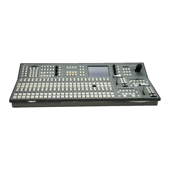
Section Control Panels Overview Kayak-100 Panel • Sources are selected in the crossbar section on the left bottom side of the panel. • Basic key control, DPM / Ram / MP / E-MEM / MaKe selection and transition control are handled in the middle sections. •... -
Page 90: Overview Kayak-200 Panel
Section 3 — Control Panels Overview Kayak-200 Panel • The top section of the panel with Keyer subpanel, Effect subpanel, Posi- tioner subpanel, Display and gadgets buttons can be delegated to M/E or P/P, • Sources are selected in the M/E1 and P/P crossbar section on the left bottom side of the panel. -
Page 91: Background Bus Selection
Background Bus Selection Background Bus Selection Figure 63. Subpanel Background Bus Selection Example: Kayak HD-100 Sources are selected on the PGM and PST row. Each row contains 15 source buttons and a button. Only one source at a time can be selected for each Shift bus on the row of interlocked buttons. -
Page 92: Button And Bus Indications
Section 3 — Control Panels Button and Bus Indications On Air Buttons involved in the output picture are indicated with a red. Uncal / Asynchronous Sources Asynchronous (non-synchronous) sources and color corrected sources are indicated by the Uncal sign on the right of the bus. 1. -
Page 93: Miscellaneous Bus Selection
Miscellaneous Bus Selection Miscellaneous Bus Selection Figure 64. Miscellaneous Bus Selection Example: Kayak HD-1 The top row of this section is the bus delegation row. Since there are more than 16 buses to be delegated, a Shift button is used to access the corre- sponding delegations. -
Page 94: Utility
Section 3 — Control Panels Utility Selecting the Util button delegates the selection bus to be the Utility bus source selector. A crosspoint selected on the Utility bus can be used as a key signal. Macro Selecting the button delegates the selection bus to be a set of macro Macro function buttons. - Page 95 Miscellaneous Bus Selection normal function of the button. This can be created in Macro attachment Play mode for all the macro attachments made. • Function only regardless whether a macro has been attached or not only the normal function is executed. •...
-
Page 96: Transition Control
Section 3 — Control Panels Transition Control Overview Figure 65. Subpanel Transition Control Example: Kayak HD-1 The transition control is performed in 3 sections. • Main Transition Subpanel with all main controls for transitions • Transition Lever Arm (Fader) for manual transition control •... -
Page 97: Main Transition Subpanel
Transition Control Main Transition Subpanel The transition controls are used to select the signal elements that will be involved in the transition (background or keys), define the type of transi- tion, and perform the transition. Second Transition Subpanel These transition controls allow the operator to cut or mix the separate keyers with individual transition times. -
Page 98: Transition Types
Section 3 — Control Panels Transition Types DPM, Mix, Wipe transition type buttons select what type of transition will be used on the elements selected above for the next transition. Pressing these buttons does not change the appearance of the current output of the switcher. -
Page 99: Performing Transitions
Transition Control Performing Transitions Auto Trans buttons and the Transition Lever Arm are used to perform main transitions. After a transition completes, the background source selections flip-flop, readying the PST bus for the next source selec- tion. The progress of a transition is indicated by the up and down arrows to the left of the lever arms. -
Page 100: Transition Preview
Section 3 — Control Panels The transition type can be changed when the M/E has reached its first preset black stage, allowing for example a wipe to and a mix from preset black. While in preset black, the key ON indicators report the states the keys will have when the second transition command completes. -
Page 101: Other Transition Control Interactions
Transition Control Pressing one of the flashing buttons delegates the Effects keypad to that transition rate and its current rate appears on the readout. A time entry is then expected on the keypad in seconds, frames, field format. Other Transition Control Interactions The Transition Lever Arm can be used in combination with the Auto Trans Cut button to perform a main transition. -
Page 102: Dd Mode Keyer Subpanel
Section 3 — Control Panels DD Mode Keyer Subpanel Figure 66. Subpanel Keyers (DD Mode) Key 1...4 These buttons delegate the Keyers Panel and indicate which keyer is cur- rently delegated to the Keyers Panel. Due to the Auto delegation the keyers panel is automatically delegated to the appropriate keyer when it makes sense. -
Page 103: Add Key
DD Mode Keyer Subpanel Note The Add Lin and Lum Lin buttons allow selecting three different operational modes (see below). The buttons are lit as follows: Table 1. Table: Key Functions Key Function Add / Lin (Lin Key) Lum / Lin (Lum Key) Additive key Multiplicative key Gain = Unity... -
Page 104: Key Sources
Section 3 — Control Panels Wipe pattern selection and other preset pattern adjustment such as softness of the preset pattern edge and size of the preset pattern shape can be adjusted in the Wipe menu. The Joystick in the Joystick subpanel, when properly delegated, controls the location of the preset pattern on the screen. -
Page 105: Strategy For Manual Chroma Key Setup
DD Mode Keyer Subpanel The default table entry for Coupled Key is . For DVEs, character gen- White erators, graphics, etc., the input where the Key signal from such an image source is connected should be coupled to the input where the video signal is connected.l Table 2. -
Page 106: Automatic Key Adjustment
Section 3 — Control Panels Automatic Key Adjustment Auto Auto button serves to start various automatic functions in the different key modes. • In the key control is switched to 1:1 transfer so that key signals Add Key, e.g. from the caption generator are effective without change. •... -
Page 107: Border On
DD Mode Keyer Subpanel 2. If there is still some transparency left. Adjust Clip Lo to make the foreground opaque and adjust clip Hi to suppress noise/shadows in the background. To help with this adjustment, turn on Show Key (aka Key PVW b/w) using the KEY PVW button. -
Page 108: Key Invert
Section 3 — Control Panels Key Invert Key Invert button reverses the sense of the key control signal. When Key Invert is active (button lit) black areas of the key cut signal cause replace- ment of the background, and the white key cut areas cause the background to be retained. -
Page 109: Default Mode Keyer Subpanel
Default Mode Keyer Subpanel Default Mode Keyer Subpanel Keyer can be used in two modes of operation. Depending on the delivery, the control panel is provided with different button legend sets. The alterna- tive button legend set is part of the delivery and can be changed by the user easily. - Page 110 Section 3 — Control Panels In Split key mode the fill source is always treated as unshaped, even if the corresponding button is on. This can be over- Engineering Setup Shaped Video ruled by the Keyer Menu Force Shaped button. Shaped Key control signal is not applied to the fill source (additive keying) Unshaped...
-
Page 111: Positioner Subpanel
Positioner Subpanel Positioner Subpanel Figure 69. Subpanel Positioner The Positioner Subpanel is used to control positioner functions of the Digital Picture Manipulator image and wipe pattern placement, size, angle, and other attributes in conjunction with the menus for the Digital Picture Manipulator. -
Page 112: Positioner
Section 3 — Control Panels Positioner The Kayak system positioner is a precision three-axis device. Moving the positioner towards or away from you controls the Y-axis, moving the joy- stick left and right controls the X-axis, and rotating the joystick controls the Z axis. -
Page 113: Dpm (Digital Picture Manipulator)
Positioner Subpanel DPM (Digital Picture Manipulator) button can be combined with the delegation buttons Key1 - 4 in the Keyer Subpanel. To toggle through the different sets of parameters of an corresponding DPM channel (Digital Picture Manipulator), just press the button or the relative Key delegation button several times. -
Page 114: Effects Subpanel
Section 3 — Control Panels Effects Subpanel Figure 71. Subpanel Effects (KayakDD Mode) Example: Kayak HD-1 The Effects Subpanel is a multi purpose section of the control panel. button is a special button, which is also used in the Trans Dur Transition Subpanel to set the transition rates for keyer and background transitions. -
Page 115: Dpm (Digital Picture Manipulator)
Effects Subpanel DPM (Digital Picture Manipulator) In DPM Mode the Effects Subpanel serves for recalling and editing DPM effects. For general information on the DPM structure in the Kayak system please refer to DPM Menus on page 228 Recalling a Register Effects can be recalled in two different modes: Register Mode and Bank Mode REGISTER MODE is an input mode for the register number in the Effects... -
Page 116: Disabling Bank Mode
Section 3 — Control Panels Display If no editing function or store function is selected, the digit display of the subpanel may show the following indications: ???? No register is selected. The register is empty. Register 24 is selected. The register is empty. -
Page 117: Selecting A Register For Storing / Editing
Effects Subpanel Selecting a Register for Storing / Editing When you press the Store or the Edit button, the current register is prompted in the display. If you want to use this register just press the button for Enter confirmation or select first another register by entering a one- or two-digit number with the numeric keypad. -
Page 118: Ram Recorder
Section 3 — Control Panels RAM Recorder In Ram Mode, the Effects Subpanel serves to control the internal RAM Recorders. To select the desired RAM Recorder channel for control, either toggle through the channels by repeatedly pressing the Ram button, or hold down the Ram button and select the according channel number. -
Page 119: Mp (Media Player)
Effects Subpanel MP (Media Player) MP Mode the Effects Subpanel serves for controlling external machines. This can be any type of device, which can be controlled by one of the machine control protocols, like video/audio tape machines, hard disk recorders, etc. To select the desired machine for control, either toggle through the avail- able machines by repeatedly pressing the button, or hold down the... -
Page 120: Hint
In the Default Mode the switcher behavior is closer to that of the Kalypso/Zodiak line of Grass Valley switchers. The DD Mode follows the E-MEM methods used by the Kayak DD line of switchers. One of the big differences between DD and Default modes is that KayakDD switchers have an Edit mode that must be activated before a Timeline can be edited. -
Page 121: E-Mem - Dd Mode Of Operation
Effects Subpanel A third difference is that in Default Mode (Kalypso/Zodiak), keyframes are always inserted behind the cursor ( ), while in DD Mode, they are Insert After inserted before the cursor position ( Insert Before ). In Default Mode both methods are available with Insert After being the default. -
Page 122: Definition Of Terms
Section 3 — Control Panels E-MEM thus permits storing and recalling individually prepared operating statuses and timelines with different background, key sources, borders, wipe pattern positioning, coloring etc. The memo system is used for storing and recalling static settings (statuses, snapshots) and interpolated timelines. -
Page 123: Display
Effects Subpanel The secondary lettering of the buttons applies when existing timelines 0 ... 9 are modified. The secondary lettering FREE of the button applies Clear when a register is selected. The secondary lettering NEXT of the Enter button applies when an assigned register is called. In the following instructions only the applicable function of the double let- tering is mentioned. -
Page 124: Enabling And Disabling Bank Mode
Section 3 — Control Panels Enabling and Disabling Bank Mode The Bank mode in the E-MEM panel permits access to a stored snapshot or timeline with a single button (hotkey). The bank number is the tens digit of the register. The hotkeys are the units digits of the register. The Bank mode may be enabled during storing but this does not have any particular ben- efit. -
Page 125: Storing A Snapshot
Effects Subpanel If the register shown in the display is to be used, no further selection is nec- essary. To select the next used register, press the NEXT button. To select a particular register, enter a one- or two-digit number with the numeric keypad. -
Page 126: Other Button Functions
Section 3 — Control Panels Other Button Functions Trans Dur Entry of the Auto transition duration. 1. Hold down the Trans dur button and press the E-MEM button. 2. Enter transition duration with numeric keypad. The time is indicated in the FRAMES display. -
Page 127: Timeline Editing
Effects Subpanel • If the E-MEM is playing a timeline, aborts playing the timeline. A Auto timeline played with can’t be stopped/continued with Auto Timeline Editing Components of a Timeline A timeline is stored as a chain of keyframes with related transitions between the keyframes and other timeline objects (e.g. - Page 128 Section 3 — Control Panels In the display of the Effects subpanel the following components of a time- line can be displayed: Start Timeline start symbol Timeline end symbol Kfnnn Internal stored keyframe SNnn Ext. stored keyframe, snapshot in register nn TLnn Ext.
- Page 129 Effects Subpanel Generating a Timeline To generate a timeline the following steps must be done: 1. Ensure that no transition or anything else is running at the E-MEM. 2. Press Edit 3. Select register. 4. Press Enter 5. Insert timeline objects (such as keyframes or loops). 6.
- Page 130 Section 3 — Control Panels Functionality of the Buttons in the Edit Mode Note Modifications of an existing timeline always relate to the last timeline object indicated in the display. This object is the currently selected timeline object. Table 7. Edit Mode Button Functions Button Functionality Store...
- Page 131 Effects Subpanel Changing the Hold Time of a Snapshot or Keyframe The following procedure is used: 1. Select (button Keyframe / Snapshot 2. Press 3. Enter hold time with numeric keypad. 4. Press Enter Note Errors can be deleted with Clear. Changing the Transition Time of a Snapshot or Keyframe The following procedure is used: 1.
- Page 132 Section 3 — Control Panels Inserting a Loop in an Existing Timeline The following procedure is used: 1. Select the timeline object after which the loop should start, or select transition before which the loop should start. 2. Press LOOP Note The loop end is before the next ELOOP or LOOP object or the end of the time- line if no other loop follows.
-
Page 133: E-Mem - Default Mode Of Operation
Effects Subpanel E-MEM - Default Mode of Operation In E-MEM mode the Effects subpanel serves for storing and recalling switcher statuses and processes. Figure 74. Subpanel Effects (Default Mode) Numeric key buttons: When TL Enable is off the numeric values 0 - 9 are used for learning / recalling registers (see below). - Page 134 Section 3 — Control Panels : With Direct turned off press a number to preview the name of the reg- ister before it is selected. Use to select the register Trim / Enter Eff Diss / Run shown in preview. Lock / Learn •...
-
Page 135: The Digit Buttons In Tl Enable
Effects Subpanel . / Undo • Pressing the . (Period or “dot) button tells the system to use the next empty register. It can also be used as a decimal point for numeric entries. • allows you to undo the previous action. You can use Undo (Shift + Undo) Undo to restore the last register you wrote over, or to undo the last editing operation you performed. - Page 136 Section 3 — Control Panels • Pressing works like the DVEous, in that if any change to This (Shift + This) the work buffer is made without a Modify or Insert, the user can press This to restore the work buffer back to the contents of the current key- frame.
-
Page 137: Make
Effects Subpanel MaKe In MaKe mode the Effects Subpanel serves for recording and playing Panel Macros. The total number of registers available for macros is 96. Figure 75. Subpanel Effects (DD Mode) Selecting a Register for Record Start For record start of a macro the register to be used for storage must be selected. -
Page 138: Recalling A Macro
Section 3 — Control Panels With the start of the recording Confirm the register selection by pressing the button. Enter Now the recording of the macro starts, while the button starts Store blinking. All keystrokes executed on the panel and in the menu, which gen- erate a command to the mainframe are recorded. - Page 139 Effects Subpanel In Bank Mode the button advances to the next used register in the NEXT bank, but in contrary to the macro is directly recalled. This Register Mode allows you to recall a stack of up to ten macros by repeatedly pressing the same button.
-
Page 140: Menu Subpanel
Section 3 — Control Panels Menu Subpanel Figure 76. Components of Timeline Example: Kayak HD-1 The Menu subpanel allows easy navigation in the menu display Home Brings you to the top menu, allowing further navigation. Menu Lock Locks the menu to the actual screen. No further auto delegation is per- formed. -
Page 141: User 1 - User 4
Half M/E (HD Only) User 1 – User 4 User definable preferred menus. Select a menu, hold down the User X button for two seconds. A short flash of the button confirms that this menu is learned. To recall the menu, just press the User X button again. -
Page 142: Feature Set Of The Half M/E
Section 3 — Control Panels Feature Set of the Half M/E Table 8. Feature Set of the Half M/E Feature Set Not implemented Features Field Dominance Wipe Transition PreRoll DPM Transition M/E Couple Chroma Key Hold Source Preset Pattern Key Drop RGB Correction Bus Correction Mix Transition... - Page 143 Half M/E (HD Only) The Half M/E is reached in the control panel by pressing the button Half M/E in the transition section (see Figure 77 on page 142). This button is labeled FTB Enable on older panels and has a circular arrow on it on newer panels. •...
-
Page 144: Operation Modes
Section 3 — Control Panels 3. Video and control couple would be set to OFF for Standard mode. Operation Modes With software release version V683 there will be two base modes of the Half M/E: • Standard Mode (Full Half M/E) •... -
Page 145: Dsk Mode Description
Half M/E (HD Only) DSK Mode Description • The Half M/E used as DSK will have 4 lum/lin keyers able to use coupled (auto select) matte signals as well as video (self) key. The pri- ority of the keyers will be able to be set - and altered via mix/dissolve on-air. - Page 146 Section 3 — Control Panels Kayak — User Manual...
-
Page 147: Section 4 - Menu Overview
Section Menu Overview Introduction The Kayak Menu panel provides capabilities that complement the opera- tion of the Main panel. The Menu panel controls most system functions, and has additional controls not available on the Main panel (for example, wipe pattern selection, chroma key manual controls, and configuration menus). -
Page 148: Touch Screen
Section 4 — Menu Overview Touch Screen CAUTION Do not apply any sharp or rigid object (no pens or pencils) to the touch screen display surface. The Menu panel touch screen allows direct interac- tion with menu controls displayed on the screen. The screen is designed to work with a finger or other soft object. -
Page 149: Menu Screen Organization And Components
Menu Panel Description Menu Screen Organization and Components Kayak system menus are context sensitive. They display different informa- tion and provide various types of controls depending on what area of the system is involved. Menus are organized into categories of related controls, which can be directly selected with touch buttons located at the bottom left of the screen. -
Page 150: Data Pads And Touch Buttons
Section 4 — Menu Overview Data Pads and Touch Buttons The Kayak system menus make extensive use of data pads. Data pads are active areas on the screen that display a summary of the status of an object, and when touched bring up additional controls and information for that object. -
Page 151: Menu Title
Menu Panel Description Menu Title The menu title is identical in all the Kayak system menus. The left portion of the menu title identifies the name of the current menu. The selected sub- category or specific mode is also displayed when appropriate. Menu Category Selection Menu category selection touch buttons are arranged along the bottom left of the screen (Mode, Priority, Mask etc. -
Page 152: Menu Access Touch Button
Section 4 — Menu Overview Function selection touch buttons either toggle on and off or are part of an interlocked group. The soft knob pads on the right allow individual param- eter adjustments, as described earlier. Additional Function Buttons In the Keyer menu, some functions are available for all delegated objects and their modes. -
Page 153: Alphanumeric Keypad
Menu Panel Description Alphanumeric Keypad Touching the pad for a text parameter brings up an alphanumeric keypad. Figure 82. Alphanumeric Key Pad Kayak — User Manual... -
Page 154: Menu And Panel Interactions
Section 4 — Menu Overview Menu and Panel Interactions The Main panel and the Menu panel graphical user interface operate as a single control surface, and so these components interact with one another. Many controls on the Main panel are duplicated on the Menu panel screens. -
Page 155: Section 5 - Kayak Menu Summaries
Section Kayak Menu Summaries In this section various Kayak system menus are presented to familiarize you with various screen layouts. Cross references are provided for more detailed information. Because each menu controls different aspects of the Kayak system, the screen parameters and organization will vary, but the basic principles previously described are followed. -
Page 156: Mouse Access To Home Menu
Section 5 — Kayak Menu Summaries Figure 83. Home Menu At system startup the Kayak brings up the menu. You can reach this Home menu at any time by pressing the button in the top left of the control Home panel. -
Page 157: Recall Preset
Home Menu Recall Preset Touching the Recall Preset button on the Home menu opens a submenu for recalling different control panel operational settings (Figure 84). Figure 84. Home Menu - Recall Preset - Recalls the factory preset. Factory Preset - Recalls the user-defined operation preset. See Install - E-Box Operation Preset Misc Menu on page 158... -
Page 158: Install Menus Overview
Section 5 — Kayak Menu Summaries Install Menus Overview The Install Menus contain system setups, most of which are only used by engineering personnel during installation. Note In this Kayak User Manual only selected Install Menu functions commonly used by operating personnel will be described. Detailed information about the Install Menus is available in the separate Kayak Installation and Service Manual. -
Page 159: Dd Modes
Install Menus Overview DD Modes Selects the operating behavior of the Kayak’s Keyer and E-MEM systems. A default setting (button not illuminated) selects behavior that is closer to that of Kalypso/Zodiak switchers. If a E-Mem DD Mode button is activated, the behavior of that system becomes more like that of the KayakDD or XtenDD switcher systems. -
Page 160: Install - Panel Misc Menu
Section 5 — Kayak Menu Summaries Install - Panel Misc Menu Touching Home Install E-Box Misc opens the Install E-Box Misc menu (Figure 85). Figure 86. Install Panel Misc Menu Pgm/ Pst Pos Sets the operation of the Program Preset busses. - Program bus flip-flops after transitions complete to always Program/Preset be above the Preset bus. -
Page 161: Load / Save Install Data
Install Menus Overview Load / Save Install Data Note The Save button is grayed out (inoperable) if a USB stick is not present in a supported control panel USB port. The Load button is grayed out if no USB stick is present or if no files are available to load from the USB stick. USB ports labeled SPARE are not supported. -
Page 162: Software Update
On the right details of the selected device are listed. Software Update Kayak system software updates are distributed on a Kayak Software Release CD-ROM, or can be downloaded from the Thomson Grass Valley web site. Software updates can be installed to Kayak system components by trans- ferring the software to a compatible USB flash drive that can be plugged into the switcher control panel. -
Page 163: Software Option Licenses
Install Menus Overview Software Option Licenses Kayak has a software option licensing system. You can see the number and type of possible licenses for your system by going to the menu Licenses under (Figure 89). Home | Install | System | Licenses The Licenses menu is used to add licenses to a system. -
Page 164: Installing Licenses
Section 5 — Kayak Menu Summaries • DSK/Half M/E (Kayak HD/SD only, not KayakDD) • RAM Recorder and KlipCache • NetCentral • HD Operation (HD/SD only) Note For basic operation licenses are required for Switcher Type, Number of Inputs, and Number of Outputs. Additional licenses for newly developed features may become available in the future. -
Page 165: Config Menus
Config Menus Config Menus After touching the Config button in the Home menu a new dialog appears with the following configuration items: • Application Control • E-Box Configuration (GPI, GPO, …) • Panel Assignment All configuration setups are part of an application and can be stored and recalled as an application. - Page 166 Section 5 — Kayak Menu Summaries Note Buttons are grayed out (inoperable) if a USB stick is not present in a sup- ported control panel USB port. USB ports labeled SPARE are not supported. - Saves the current application. Save - Saves the current application with a selectable file name.
-
Page 167: E-Box Configurations
Config Menus Figure 92. Config – Application Control – Change Devices 3. Select the IP address of the desired device and press to update the application file. E-Box Configurations After touching the E-Box button in the Config menu a new dialog displays with various configuration items (Figure 93). -
Page 168: Config - Gpi Menu
Section 5 — Kayak Menu Summaries Config - GPI Menu General Purpose Interface Inputs (GPI Inputs) can be used by an external device to trigger an action on the Kayak system. See Installation Manual for pinout specifications. The Config-GPI menu allows programming up to 32 system GPI inputs (8 per M/E). -
Page 169: Config - Gpo / Tally Menu
Config Menus Figure 95. Config - GPI Functions Config - GPO / Tally Menu The General Purpose Interface Output/Tally menus are used to configure the tally system. There are multiple tally calculators, three different tally calculation methods, and user assignment of tally relays. The results of the tally calculators are applied to the tally relays on the Video Processor frame, and those relays control external tally lights. - Page 170 Section 5 — Kayak Menu Summaries The On Air Tally (Red Tally) calculations are essential for switcher opera- tion. This tally calculation forms the basis for On Air indication (panel, camera tally lights, etc.), and other functions such as external device Auto Start, Off Air Advance, or router protections.
- Page 171 Config Menus Figure 96. Config - GPO Menu Touching the button calls a sub-menu. In this menu the tally mode of Modify the selected GPO channel 1 – 128 can be configured. Kayak — User Manual...
- Page 172 Section 5 — Kayak Menu Summaries Figure 97. Config - GPO / Tally Mode Selection No tally is selected None: On Air Tally is selected Red: Look Ahead Tally is selected Yellow: Isolated On Air Tally is selected Green: Kayak — User Manual...
-
Page 173: Config - Input Menu
Config Menus Config - Input Menu The Config - Input menu is used to name sources and couple keys for sources (Figure 98). Figure 98. Config - Input Menu Naming Sources The Name of a source is displayed on the Control panel, and is limited to four characters. - Page 174 Section 5 — Kayak Menu Summaries Coupling Keys Touching the button calls a sub-menu. In this menu the Key Modify Cpld Key to be coupled to the selected fill source can be selected (Figure 99). Figure 99. Config - Coupled Key Menu 1.
- Page 175 Config Menus Config - AUX Menu Figure 100. Config - AUX Menu The Safe Title adjusting elements enable fading–in different auxiliary lines (Box, Cross) into each individual AUX bus. The fade-ins serve as an auxil- iary means to mark production-defined picture areas (e.g. areas for logos, subtitles, 4:3 raster).
-
Page 176: Config - Aux Couple Menu
Section 5 — Kayak Menu Summaries Config - AUX Couple Menu Figure 101. Config - AUX Couple Menu The AUX Couple menu serves for coupling the AUX bus to other switcher buses (masters). If the source on the master is changed, the source on the coupled AUX bus follows automatically. -
Page 177: Config - M/E Menu
Config Menus Config - M/E Menu Figure 102. Config – M/E Menu menu serves to configure the cleanfeed layer. Config – M/E Figure 103. Config – Cleanfeed Layer Kayak — User Manual... -
Page 178: Config - M/E Couple Menu
Section 5 — Kayak Menu Summaries Config - M/E Couple Menu M/E Couple is used to support an additional transmission line output on a switcher whose main parts are identical to that of its main output, but differs in country specific video components (source and/or keyer substi- tution). - Page 179 Config Menus Examples: • Serial: PP to ME3 to ME2 ME3 is coupled to P/P ME2 is coupled to ME3 ME1 is not coupled • Parallel: PP to ME3; PP to ME2 Both, ME3 and ME2 are coupled to PP. ME1 is not coupled. •...
- Page 180 Section 5 — Kayak Menu Summaries By selecting in the ME Main menu, M/E Coupling can be acti- ME Couple vated or deactivated for each resource. • button: Key bus only Key Couple • button: complete ME. Comp Couple Figure 105. ME Main Menu E-MEM Handling M/E coupling works on command level.
-
Page 181: Config - Dpm Menu
Config Menus Config - DPM Menu Figure 106. Config – DPM Menu The production crop settings allow you to adjust an overall crop for the DPM channels. Additional cropping per channel is possible in the menu. DPM/Transform/Crop Kayak — User Manual... -
Page 182: Config - Substitution Tables Menu
Section 5 — Kayak Menu Summaries Config - Substitution Tables Menu Figure 107. Config – Substab Menu Config Substab menu serves to configure up to 15 substitution tables. These tables can be used by coupled AUX buses or coupled M/Es to exchange the source when the coupled AUX bus follows its master. -
Page 183: Config - Editor Menu
Config Menus Config - Editor Menu Figure 108. Config – Editor Menu Config Editor menu allows you to re-direct external editing system com- mands to different Kayak system outputs. Use the button to select Delegation the desired editor, select the desired parameter, and then touch Modify select an alternative target setting for the editor command. -
Page 184: Config - H/V Blanking Menu
Section 5 — Kayak Menu Summaries Config - H/V Blanking Menu H/V blanking settings that used to only be accessible with the Sidepanel program are now available on a Kayak menu. Select to bring up the menu (Figure 109). Config E-Box H/V Blanking Figure 109. -
Page 185: Config Tally In Menu
Config Menus Config Tally In Menu Figure 110 shows the basic configuration menu for different Tally calcula- tions methods. In this menu one or more output channels can be activated for signalling. • - On Air Tally - for source and monitor signalling Red Tally •... -
Page 186: Config - Misc Menu
Section 5 — Kayak Menu Summaries Config - Misc Menu Figure 111. Config – Misc Menu AUX PVW (Preview) / Bus Auto AUX Preview button: On/Off: Enable or disable the Auto PVW mode. In the enabled condition, the key PVW, mask PVW, or the chroma key cursor signal of the respective mixing level, is switched on the PVW bus. - Page 187 Config Menus Field Dominance The button can be used to switch over between Any Field, Field1 Field2 The setting concerns the switching of the crosspoints on all buses, the start of auto transitions, switching with Cut and the recalling of snapshots and timelines.
- Page 188 Section 5 — Kayak Menu Summaries Half M/E Configuration Figure 112. Config – Half M/E - Select Coupled Mode Use the “Half M/E Mode” button to select the mode, and the “Coupled To” button to select the full M/E to couple the Half M/E to. •...
- Page 189 Config Menus Figure 113. Config – Half M/E - Select Coupled M/E Select the full M/E to couple to the Half M/E. Remote I/O Enable buttons The Remote button group has to be used to enable the following functions: • Enables AUX control panels •...
-
Page 190: Config - Flexible Licenses Menu
Section 5 — Kayak Menu Summaries Config - Flexible Licenses Menu The Flexible Licenses menu is used to assign Chroma Keys. Touch the button then select the desired keyer. Modify Figure 114. Config – Flexible Licenses Menu Figure 115. Config – Flexible Licenses Chroma Key Selection Menu Kayak —... -
Page 191: Config - Scalar Menu
Config Menus Config - Scalar Menu Figure 116. Config – Scalar Menu The Config - E-Box - Scalar Menu is used to configure Scalar conversion. See Scalar Configuration on page 319 for more information. Kayak — User Manual... -
Page 192: Panel Assignment
Section 5 — Kayak Menu Summaries Panel Assignment The Panel Assign menu serves to assign the hardware inputs and internal sources to the source buttons of the Kayak control panel. Figure 117. Config – Panel Assign Menu The legend of the first button on the left ( All Bus Rows Figure 117) indicates... - Page 193 Config Menus Figure 118. Config – Panel Assignment - Bus Row Selection Menu Pressing Reset Assignment opens an dialog with some pre-defined input assignments (Figure 119). Figure 119. Config – Panel Assignment – Reset Kayak — User Manual...
- Page 194 Section 5 — Kayak Menu Summaries - Copies the input assignment from the Bgnd bus row into the key Like Bgnd bus row (only for key buses) Like AUX All - Copies the input assignment from the AUX All bus row into the selected bus row.
-
Page 195: Personal Settings Menus
Personal Settings Menus Personal Settings Menus Figure 120. Personal Settings Menu Digipots and Low Light - Basic brightness of all push buttons of the control panel. This Low Light control is only available on panels that support this function. For example, this control is missing on 2-M/E control panels (not supported) but is present on 1 M/E panels. -
Page 196: Macro Attachment
Section 5 — Kayak Menu Summaries Macro Attachment Touching the Macro Attachment Play Mode button calls a sub-menu. In this menu the Play mode of the selected macro can be configured. • Function Only • Function & Macro • Macro Only Async Blinking Asynchronous (non-synchronous) sources and color corrected sources are indicated by the same Uncal sign on the right of the bus. -
Page 197: Wipes Menus
Wipes Menus Wipes Menus Wipe menus allow selection and modification of wipe patterns. The Wipe menus, like the Keyer menus, have a delegation popup button In the upper left area, the button next to it contains a pattern touch pad, which displays the currently selected wipe pattern (Figure 121). - Page 198 Section 5 — Kayak Menu Summaries Matrix Wipes consisting of sequential revelation of picture squares (matrix wipes) In addition to providing standard patterns, the Kayak production switcher offers the possibility to prepare and store user-defined wipe patterns. Wipe button in the Transition subpanel is a DPOP (Double-Press Open) button;...
-
Page 199: Point Of Use
Wipes Menus Point Of Use Only the controls which affect the pattern generator itself are adjusted in the wipe menu. Other parameters like size, border, direction, which are dif- ferent per point of use are set in the corresponding M/E or Keyer menus. For operating simplicity, you may decide to use the Complex wipe genera- tors (Wipe1 and Wipe2) for main transitions, and the simpler Box and Keyer wipe pattern generators for the keyers. -
Page 200: Wipe Pattern Number Code
Section 5 — Kayak Menu Summaries Wipe Pattern Number Code The available wipe patterns and their assigned codes are included in the figures below. Codes are named according to ANSI/SMPTE 258M. Code names in paren- thesis (xx) are GV pattern numbers. Page 1 –... -
Page 201: Page 2 - Circle And Rotary
Wipes Menus Page 2 – Circle and Rotary Figure 125. Page 2 – Circle and Rotary Table 10. Page 2 - Circle and Rotary Respective Code Numbers (13) (28) (12) (22) (32) (14) (34) (16) Kayak — User Manual... -
Page 202: Page 3 - Stars And Zigzag
Section 5 — Kayak Menu Summaries Page 3 – Stars and ZigZag Figure 126. Page 3 – Stars and ZigZag Table 11. Page 3 – Stars and ZigZag Respective Code Numbers (40) (41) (27) (42) (43) (44) (59) (15) (18) (25) (26) (36) -
Page 203: Page 4 - Matrix Wipes
Wipes Menus Page 4 – Matrix Wipes Figure 127. Page 4 – Matrix Wipes Table 12. Page 4 – Matrix Wipes Respective Code Numbers (29) (52) (48) (51) (49) (19) (50) (47) (56) (57) (53) (55) (54) (38) (39) Kayak — User Manual... -
Page 204: Wipe Modifier
Section 5 — Kayak Menu Summaries Wipe Modifier Using the modifiers like H/V Multi, Mix/Ratio/… Mod/Lock/… the standard wipe patterns can be changed and new patterns can be created. In dependence of the chosen Modifier the menu changed. The soft knobs on the left of the screen are used to control the various parameters. - Page 205 Wipes Menus Figure 129. Wipe Menu – Modifier 3 – Allows control of the pattern mix function. Patterns may be Mix, Ratio, … mixed or non-add mixed with the Mix Type control data pad. The ratio may be chosen by touching the Ratio data pad to bring up the numeric keypad.
- Page 206 Section 5 — Kayak Menu Summaries Figure 130. Wipe Menu – Modifier 3 - Allows enabling and control of the modulation wipe Mod, Lock, Wave, … functions. Patterns may be modulated vertically or horizontally with four different waveforms (Square, Sine, Sawtooth and Triangle). Soft knobs on the right of the screen control amplitude and frequency of the H and V modulation.
-
Page 207: Keyer Menus
Keyer Menus Keyer Menus The Keyer menu controls are organized into several subcategories, each with different menu selection based on the type of key. These menus are accessed by touching the button in the Home menu. Keyer selections Keyer like key type, , can be made for any keyer from the Main Key Invert, Matte Fill panel using the Keyers subpanel. -
Page 208: Key Mode
Section 5 — Kayak Menu Summaries Key Mode Figure 132. Keyer Menu – Mode Selection (Default Mode) Figure 133. Keyer Menu – Mode Selection (DD Mode) Kayak — User Manual... - Page 209 Keyer Menus The Mode menu allows you to select the type of key for any of the four keyers in each M/E or P/P. Touching the subcategory button brings Mode up the Keyer Mode menu. Touch the keyer data pad you wish to select, then select the Mode from one the selections described below.
-
Page 210: Keyer Priority Misc Menu
Section 5 — Kayak Menu Summaries Keyer Priority Misc Menu Touching the Priority Misc subcategory button takes you to the Priority menu (Figure 134). The Priority menu is used to change the stacking order of the keys. The parameter control area on the right has two columns, labeled Current . -
Page 211: Keyer Mask Menu
Keyer Menus Keyer Mask Menu Touching the Mask subcategory button takes you to the Keyer Mask Point of Use menu (Figure 135). The Mask menu allows selection and control of the keyer mask(s). Key masking defines areas that are protected from keying (Inhibit) or always key (Force). -
Page 212: Mask Sources
Section 5 — Kayak Menu Summaries Mask Sources For either type of selected mask (Force or Inhibit) five different mask sources are available and will appear as popup selection when you press button. Mask Source Only one mask source can be selected at a time. Figure 136. - Page 213 Keyer Menus When is selected as the mask source, you can adjust softness and opacity. The four edges of the box can be set separately. Figure 137. Keyer Menu – Box Mask Kayak — User Manual...
- Page 214 Section 5 — Kayak Menu Summaries Keyer Wipe A Keyer Wipe mask source allows selection of a wipe pattern from the ded- icated pattern generator for the keyer. Touch the Patt. Sel/Adj button in the menu to bring up the wipe pattern selections available (Figure 138).
- Page 215 Keyer Menus Utility Bus mask sources originate from the utility bus in the chosen Utility Bus M/E. Typically these are used to bring in garbage masks from a RAM Recorder (Still Store) or some external device. Figure 139. Keyer Menu – Utility Bus Mask Mask On Button The Mask may be turned on or off by selecting the button.
-
Page 216: Keyer Mattes Menu
Section 5 — Kayak Menu Summaries Keyer Mattes Menu The Matte menus give you control over matte color, type, and appearance. There are no local matte controls on the Main panel; all matte adjustments are made in the menus. The popup delegation button in the top left of the menu allows you to select the mattes of the different keyers. -
Page 217: Chroma Key
Keyer Menus Chroma Key When a chroma key is selected, the menu (Figure 142 on page 217) will display a summary of all chroma key parameter values at the same time. The parameter groups should be adjusted in the following order: 1. -
Page 218: Preset Pattern
Section 5 — Kayak Menu Summaries Preset Pattern A preset pattern uses a wipe pattern generator, rather than an incoming key cut signal to define the hole cut in the background. When Preset Pattern chosen as the keyer mode, the menu will appear as in Figure 143 below. -
Page 219: Background Mattes Menus
Background Mattes Menus Background Mattes Menus Background matte generators create colors, and washes. These can be used, for example, as the backgrounds for keys. When is selected, the menu displays two panes for control of Bgnd Mattes Color BGD 1, Color BGD 2, Color BGD 3, and Test patterns including base and wash colors, wash direction and offset, and wash edge texture attributes. - Page 220 Section 5 — Kayak Menu Summaries If Test Pattern is selected, a new menu appears. The Patterns menu allows the selection of different video test patterns. The chosen test pattern will be displayed when the Test source is selected. Figure 146. Test Pattern Selection Touch the Color Output pad, then select the desired color output: Flat single color matte with button .
- Page 221 Background Mattes Menus Figure 147. Background Matte Menu - Wash Kayak — User Manual...
-
Page 222: M/E Menus
Section 5 — Kayak Menu Summaries M/E Menus The M/E menu controls are organized into two subcategories, each with different menu selection based on the type of transition. These menus are accessed by touching the button in the Home menu. Typical selections are Pattern Source, Pattern Direction, Border and Softness. - Page 223 M/E Menus Figure 149. M/E Menu – Border Matte Kayak — User Manual...
-
Page 224: Yuv Bus Correction Menus
Section 5 — Kayak Menu Summaries YUV Bus Correction Menus The YUV Correction menu serves to adjust brightness, contrast, saturation and color balance related to the bus. Figure 150. YUV Bus Correction Menu The correction can be made in the following buses: •... - Page 225 YUV Bus Correction Menus Color Off Switched the color on/off completely separate for each bus. Kayak — User Manual...
-
Page 226: Rgb Input Correction Menus
Section 5 — Kayak Menu Summaries RGB Input Correction Menus RGB Input Color Correction is a software enabled feature that converts the video signal on a particular video bus from color difference format to RGB (red, green, blue) color component format, applies separate offset, gain, and gamma to each RGB component, then converts from RGB back to color difference (Y, Cb, Cr) format. - Page 227 RGB Input Correction Menus When the button is touched, the following modes can be selected: Reset • Reset Color • Reset Input • Reset all Inputs When one of the Green , or Blue color component's button is selected, the knobs for Gain, Lift, and Gamma are delegated for the specific component.
-
Page 228: Dpm Menus
Section 5 — Kayak Menu Summaries DPM Menus The Kayak system supports one DPM (Digital Picture Manipulator) channel per keyer. A Kayak HD-100 and Kayak DD-1 may have up to 4 DPM channels and a Kayak HD-200 and Kayak DD-2 up to 8 DPM chan- nels. -
Page 229: Misc Setup Menu
DPM Menus Misc Setup Menu Figure 153. DPM – Misc - Setup Menu This menu is the start menu for building an effect. In the top row you select which channels should be part of the effect. Channels that are not included will not be stored and will not be affected when the register is recalled. - Page 230 Section 5 — Kayak Menu Summaries In the Key – Priority – Misc menu you can switch on DPM effect loop for the chosen keyers (Loop On) and select the flipside of an effect (Use Src). This information is not part of a DPM effect and should be set manually or recalled by an E-MEM recall (like the keyer parameter settings).
-
Page 231: Transform Menus
DPM Menus Transform Menus Figure 155. DPM – Key 1 -Transform Menu All parameter manipulations for the DPM channels are performed in the various transform menus. The main groups Locate, Skew, and Crop are selected in the bottom right corner of the screen. Inside the main group you can select the subgroup, e.g. Locate, Locate Axis, Target Rot., and Spin by pressing the appropriate button. -
Page 232: Edit Gang
Section 5 — Kayak Menu Summaries Edit Gang Edit Gang button shows you for which channels parameters are adjusted in parallel. If more than one channel is selected, the values of the top channel are displayed. Figure 156. DPM – Edit Gang Selection You can select all Keyer channels which are included in this effect. -
Page 233: X, Y, Z Spin
DPM Menus X, Y, Z Spin For the subgroup Spin the path type can be different for the X,Y, and Z spin. Figure 158. DPM – Spin Selection To adjust the parameters for Tension, Continuity, and Bias press the rele- vant button in the path control section. -
Page 234: Crop
Section 5 — Kayak Menu Summaries Crop Figure 160. DPM – Key 1 – Transform - Crop The menu serves to trim the image. In addition the softness of the edges can be adjusted and the image can be mirrored horizontal and vertical with Reverse Front Reverse Back . -
Page 235: Timeline Menus
DPM Menus Timeline Menus The timeline menus consist of two main groups, Save/Recall and Edit. Save / Recall Menu Figure 161. DPM – Timeline – Save/Recall Menu This menu gives you an overview of all 100 registers. You can select any register for recall, edit or modify. -
Page 236: Save / Discard
Section 5 — Kayak Menu Summaries Save / Discard This button is only enabled when you have modified the current effect in the Timeline/ Edit menu. Once you have made changes the pop-up menu shown below allows you to either save the changes permanently or discard them. -
Page 237: Modify
DPM Menus Modify Modify button allows you to rename, delete, cut, copy, paste, or undo the last action to the selected register. Figure 163. DPM – Timeline – Modify Use Priority If the button is activated, the key priority of the included keyers Use Prio. -
Page 238: Loop
Section 5 — Kayak Menu Summaries Figure 164. DPM – Timeline – Video Sources Loop This function allows you to put the selected effect in an endless loop: Run from begin to end. Loop: Run begin to end, then reverse to begin, etc. Bounce: Figure 165. -
Page 239: Show Timeline Menu
DPM Menus Show Timeline Menu Figure 166. DPM – Show Timeline – Edit Menu The Edit menu allows you to insert/modify/delete keyframes for the selected channels for the current effect. Delegation button shows you for which channels the actions are exe- Delegation cuted. -
Page 240: Sure Touch
Section 5 — Kayak Menu Summaries Sure Touch Sure Touch changes the way in which effects behave during recall and play- back, providing more control and flexibility. An effect can be safely recalled using two new modes which eliminate abrupt changes: hence the name Sure Touch is being used. -
Page 241: Cursor Control
DPM Menus Cursor Control The top row buttons Go To, Begin, Rev Play, Pause, Play , and let you run the current effect or position the cursor to a specific keyframe. The effect posi- tion can also be adjusted by the digipot. -
Page 242: Modify Keyframe
Section 5 — Kayak Menu Summaries Modify Keyframe Figure 170. DPM – Timeline – Modify Keyframe Note When the cursor is at a keyframe, the parameters of this keyframe will be modified to the current values, When the cursor is between keyframes, modify inserts a keyframe at the current position without adding any time. -
Page 243: Delete Keyframe
DPM Menus Note When the cursor is at a keyframe, a new keyframe will be inserted, adding the time which is specified with Keyframe Duration, When the cursor is between keyframes, the keyframe is inserted at the current position without adding any time. -
Page 244: Constant Duration
Section 5 — Kayak Menu Summaries Note The Keyframe Duration button is not used to change the keyframe duration of the current keyframe. The time is used for the insert of a new keyframe when inserted while the cursor is on a keyframe (see Insert Keyframe). Constant Duration The function of this button is the same in both modes. -
Page 245: Specfx Menu
DPM Menus SpecFX Menu The Transform Engine Spektra Effects option includes Glow, Defocus, and the new Lighting functions. Glow adds a soft edged variable opacity border around keys, leaving the original keyed image unmodified. Defocus blurs the actual keyed image. The new Lighting provides four oppositional colored light sources that apply a specular appearance to the transformed picture. - Page 246 Section 5 — Kayak Menu Summaries Figure 175. DPM – SpecFx – Kurl Menu (Off) Kayak — User Manual...
-
Page 247: Selecting The Kurl Mode
DPM Menus Selecting the Kurl Mode Kurl Mode button allows you to select different operating modes. Figure 176. DPM – SpecFx – Kurl Mode Selection Kayak — User Manual... -
Page 248: Page Turn / Roll Mode
Section 5 — Kayak Menu Summaries Page Turn / Roll Mode Figure 177. DPM – SpecFx – Kurl Menu (Page Turn Mode) Page Turn is a transition effect with the video being mapped to an original plane, a cylinder, and a final plane parallel to the original plane. Page Roll maps the video to an original plane and a cylinder. -
Page 249: Page Fold
DPM Menus Page Fold When the Page Fold data pad is selected, the following soft knob controls are available: • Radius Adjusts the radius of the page turn cylinder affecting the sharpness of the curl. • Angle Defines the orientation of the page turn cylinder with respect to the source X and Y axes, and specifies the direction of the turn. -
Page 250: Pos / Size Mode
Section 5 — Kayak Menu Summaries Pos / Size Mode Figure 178. DPM – SpecFx – Kurl Menu (Pos/Size Mode) Position and Size Modulation are effects in which the source video is posi- tion- or size-modulated through an additive process with either a single wave train, or two wave trains with the second wave at a right angle to the first. - Page 251 DPM Menus Phase When Phase Lock is on, the Phase soft knob is available to control the static location of the phase of the pattern. When Phase Lock is off, the Speed soft knob is available to adjust the speed of the pattern’s motion.
- Page 252 Section 5 — Kayak Menu Summaries Pattern Pane: The type of wave pattern to be applied to the selected axis and modulation type is selected in the Pattern pane. Figure 180. DPM – SpecFx – Kurl Menu (Pattern Selection) Figure 181. Available Wave Patterns Normal + Only Normal...
- Page 253 DPM Menus Figure 182. DPM – SpecFx – Kurl Menu (Pos/Size Mode) Cycle Limiting Cycle Limiting Button activates the Cycles soft knob. This control can be used to limit the number of wave pattern cycles visible. Note When applying Cycle Limiting, only a portion of the video image may have the pattern applied.
-
Page 254: Slits Mode
Section 5 — Kayak Menu Summaries Slits Mode Slits is an effect in which the source video is split into a number of parallel slits. The width of the slits may be uniform or random, and an angle may be specified. An offset function is provided which controls the amount of displacement of alternating slits in opposite directions (to cause a transition type effect). - Page 255 DPM Menus Figure 184. DPM – SpecFx – Kurl Menu (Slits Mode) Soft knob controls are provided to control the following attributes of the slits: Offset Sets the distance adjoining slits move away from each other. This can be used for transition effects, using a zero offset for the first keyframe and an off-the-screen offset for the last keyframe.
-
Page 256: Advanced Effect Options (Hd-Only)
Section 5 — Kayak Menu Summaries Advanced Effect Options (HD-Only) Kayak HD systems equipped with the Advanced Effects option have addi- tional Glow, and menus. Glow adds a soft edged variable opacity border around keys, leaving the original keyed image unmodified. Defocus blurs the actual keyed image. These features are available only when the respective license key has been activated. -
Page 257: Defocus Effect
DPM Menus Glow Mode Pane • Off — The Glow effect is deactivated. • Glow — The Glow effect is applied around the keyed image which remains visible. • Glow Only — The glow effect is applied to the entire keyed area, replacing the original keyed image. - Page 258 Section 5 — Kayak Menu Summaries Figure 186. DPM – SpecFX – Defocus Mode Defocus Mode Pane • Off — The Defocus effect is deactivated. • Defocus — The Defocus effect is applied to the original keyed image. • Defocus NAM + — The defocused image is compared to the original image on a pixel by pixel basis, and the lighter (higher luminance) pixel of the two is used in the final image.
-
Page 259: Drop Shadow
DPM Menus NAM Matte Pane Figure 187. DPM – SpecFX – Defocus Mode - NAM Matte NAM Matte Enable — When selected a matte color is applied to the selected NAM (lighter or darker) portion of the keyed image. When the NAM Matte pane is activated, knob controls for matte Hue, Sat- uration, and Brightness become available. - Page 260 Section 5 — Kayak Menu Summaries Figure 188. DPM – SpecFX– Drop Shadow 1 When Shadow is selected soft knobs for X Offset, Y Offset, Size , and Opacity are available (Figure 188). When is selected soft knobs for , and Shadow Color Hue, Saturation Brightness...
-
Page 261: Shadow Crop
DPM Menus Figure 189. DPM – SpecFX– Drop Shadow2 Drop Shadow Controls button near the 3D positioner delegates it to drop shadow control. The 3D positioner X and Y axis adjust the drop shadow offset from the primary image and the Z axis controls the size of the drop shadow. Shadow Crop controls are used to adjust shadow cropping and edge soft- Shadow Crop... -
Page 262: Lighting Menu
Section 5 — Kayak Menu Summaries Figure 190. DPM – SpecFX– Shadow Crop When Use Image Crop is selected, crop values of the shadow match the crop values used for the primary image. Only shadow edge softness controls are active in this mode. When the Crop Softness data pad is selected soft knob controls for shadow... -
Page 263: Source Pane
DPM Menus lighting effects would be impossible. For this reason, values that might cause aliasing are allowed. If a lighting effect creates unwanted results, set- tings can be adjusted. The Lighting menu is accessed via SpecFX Lighting Figure 191. Typical Lighting Menu Source Pane The buttons in the Source pane delegate the menu to a particular light source 1 to 4. -
Page 264: Position
Section 5 — Kayak Menu Summaries simulates a spotlight type of lighting effect that radiates light evenly Point — in all directions. Bar — simulates lighting from a bar-shaped long, thin lighting source. Plane — simulates a parallel light striking the entire surface of the video. Position Used with light sources to control the position of the point... -
Page 265: Light Color / Flare Color
DPM Menus on the menu will not be different, but the changes will interact automati- cally to create the resulting image. When On, changing the values for one lighting component will not alter the appearance of the other component. Light Color / Flare Color Provides soft knob controls of the Hue, Saturation, and Brightness of the Light or Flare lighting. -
Page 266: Misc Menu
Section 5 — Kayak Menu Summaries Misc Menu Figure 192. DPM – Misc– Misc Selection Setup Select the included keyer and allow global control. See Misc Setup Menu for details. page 229 Set to Defaults To reset all Digital Picture Manipulator parameters or groups of them to default you can use the Set to Defaults menu which is accessible through the Misc selection in the button row. - Page 267 DPM Menus Figure 193. DPM – Set to Default Figure 194. DPM – Default Selection Figure 195. Kayak — User Manual...
-
Page 268: Digital Effects Library
Section 5 — Kayak Menu Summaries Digital Effects Library The DPM effect library is provided to give users examples of the capabili- ties of the internal DPM as well as a starting point to create own effects. The library is in 2 sections: •... -
Page 269: How To Load The Effects To Your Switcher
DPM Menus Figure 196. Config - DPM – Timeline – Modify How to Load the Effects to Your Switcher Use the USB flash drive for your system to make a copy of your working application. 1. Insert your USB flash drive in USB slot 2 or 4. 2. - Page 270 Section 5 — Kayak Menu Summaries Figure 197. Copy To Button 7. In the window that opens navigate to your USB flash drive and open the appli folder. In this navigate to the folder named as you named your copy of the active application on your Kayak HD™ and then to the MF1 folder.
- Page 271 DPM Menus Figure 198. Copy Items You do not have to copy both te_eff0 and te_eff1 to a 2 M/E Kayak HD™ unless you want both mix effect banks to have access to the effect library. You do not have to copy the same library (C1fx or C4fx), so you could use C1fx from te_eff0 and C4fx from te_eff1.
-
Page 272: Catalog Of Effects
Section 5 — Kayak Menu Summaries Catalog of Effects Naming Table 13. Effect Naming Conventions Type slide perspective slide linear motion bounce spir spiral multi position bounce swoop barrel roll in barrel roll out Positions in or out of frame Top Centre Bottom Centre Left Centre... -
Page 273: C1Fx - For Channel 1 Only
DPM Menus C1fx – for Channel 1 Only All effects in the C1fx section may be used with either full frame pictures or keyed elements. C1fx - Bank 00 Table 14. Slide and zoom with shadows. Effects are 1:00 second Zoom Out C1sl-LC C1sl-RC... - Page 274 Section 5 — Kayak Menu Summaries C1fx - Bank 03 Table 17. Linear Bounce C1bncOUT C1lb-LC C1lb-RC C1lb-TC C1lb-BC C1bncIN C1lb-CL C1lb-CR C1lb-CT C1lb-CB C1fx - Bank 04 Table 18. Swoop IN/OUT C1sw-OUT C1sw-TLC C1sw-TRC C1sw-BLC C1sw-BRC C1sw-IN C1sw-CTL C1sw-CTR C1sw-CBT C1sw-CBR C1fx - Bank 05...
-
Page 275: C4Fx For Kayak Hd™ System
DPM Menus C4fx for Kayak HD™ System This Kayak HD system has 4 DPM Channels per M/E and the Advanced Effects Option: C4fx: Bank 00 Table 20. Push on/of QUAD-ON Brings all 4 channels in from corners C12sl-LR Slides C1 off screen, slides C2 on screen C12sl-RL Slides C1 off screen, slides C2 on screen C12sl-TB... - Page 276 Section 5 — Kayak Menu Summaries C4fx: Bank 03 Table 23. Page Rolls full size C1pgr-ON C2pgr-ON C3pgr-ON C4pgr-ON C1pgr-OFF C2pgr-OFF C3pgr-OFF C4pgr-OFF C1pgr-ON C2pgr-ON C4fx: Bank 04 Table 24. Double sided page turns and page rolls C12pgt-ON C34pgt-ON C12pgt-OFF C34pgt-OFF C12pgr-ON C34pgr-ON...
-
Page 277: Notes
DPM Menus C4fx: Bank 06 Table 26. Tiles and modulation C1twinH C1twinV C1quad C12twin C1mod C1expld C1slitsON C1slitsOFF C1twinH C1twinV Notes Use of GLOBAL Channel Although GLOBAL channel is supported, certain aspects may behave in a non-intuitive manner. Most of the effects in these libraries do not use GLOBAL, but cubes and push/pull effects do. -
Page 278: Hd Ram Recorder Menus
Section 5 — Kayak Menu Summaries HD RAM Recorder Menus The HD RAM Recorder menu is accessed via the Home Menu. Figure 199. Home Menu Kayak — User Manual... -
Page 279: Stills Menu
DPM Menus Stills Menu The Stills menu allows the user to load or store stills using the delegated channels. Figure 200. RAM Recorder Stills Menu Delegation Pane Select the desired channel (1 to 6) with the Delegation button. The menu shows the values of the selected channel. -
Page 280: Clip Select Menu
Section 5 — Kayak Menu Summaries Clip Select Menu Clips can be selected with the Clip Select Menu. Figure 201. RAM Recorder Clip Select Menu — Selects the clip to the output of the delegated channel. Load Clip — Renames the selected clip and makes automatic name Rename Clip changes for associated key signals. -
Page 281: Clip Play Menu
DPM Menus Clip Play Menu The Clips Play menu provides the control for playing a clip. Figure 202. Clip Play Menu Tape Motion Commands (TMC) — Moves clip to the beginning Begin — Moves clip to the end < (Play Reverse) —... -
Page 282: Modify
Section 5 — Kayak Menu Summaries Modify Modify allows you to modify the values displayed in the main display area. After pressing the button a dialog appears to modify the play parameters. Figure 203. Clips Play Modify Dialog Go to timecode —... -
Page 283: Clip Record Menu
DPM Menus Field 1 and field 2 is displayed to make a full frame. Frame: Step-/Step+ advances to field 1/2 of the next frame Field1/2: Field 1 and field 2 are displayed as a full frame. Step-/Step+ advances to the next fields, which results in single stepping in field resolution. Readout Play Field 1: Only field 1 is played out resulting in "Film look"... - Page 284 Section 5 — Kayak Menu Summaries Figure 204. Clip Record Menu —Starts recording a new clip. Clip position and clip name will be Record New created automatically. Record Edit —Starts recording in an existing clip at the current position. The system allows recording over the end of the current clip, which results in appending to the current clip.
-
Page 285: Tape Motion Commands (Tmc)
DPM Menus Tape Motion Commands (TMC) Begin — Moves clip to the beginning — Moves clip to the end < (Play Reverse) — Play the clip reverse — Play the clip forward > (Play Forward) — Advances one field or frame Step + / Step - —... -
Page 286: Hd Ram Recorder Live Mode Menu
Section 5 — Kayak Menu Summaries Figure 205. RAM Recorder Active Area Menu — Position and crop the a stored clip on the screen Enable Playout Record Area — Crop the area to record Playout Area — Crop a portion of recorded clip to playback Playout Offset —... -
Page 287: Stills Recall / Clips Recall
DPM Menus Figure 206. Live Mode Stills Recall Stills Recall / Clips Recall 1. Select the delegated RAM channel via the Delegation button 2. Select the delegated bank 0 to 23 via the Bank button 3. Select the group of stills, e.g. 0-19 Kayak —... -
Page 288: Setting The Hd Ram Recorder Ip Address
Section 5 — Kayak Menu Summaries Setting the HD RAM Recorder IP Address The IP address of the RAM Recorder will be set automatically by the system during installation. IP Address = Mainframe IP address + 1 The IP address can be set manually by using the Device Control menu. Figure 207. -
Page 289: E-Mem Menus
Default Mode of Operation In the Default Mode the switcher behavior is closer to that of the Kalypso/Zodiak line of Grass Valley switchers. The DD Mode follows the E-MEM methods used by the Kayak DD line of switchers. One of the big differences between DD and Default modes is that KayakDD switchers have an Edit mode that must be activated before a Timeline can be edited. -
Page 290: E-Mem Define Memo Menus
Section 5 — Kayak Menu Summaries E-MEM Define Memo Menus Figure 208. E-MEM – Define Memo PP The Define Memo menu serves to define the function groups of the Kayak HD switcher, which are be stored or recalled in an E-MEM snapshot or timeline. - Page 291 E-MEM Menus Page for selecting the ME1 switcher functions: Figure 209. E-MEM – Define Memo ME1 Page for selecting miscellaneous internal M/E switcher functions: Figure 210. E-MEM – Define Memo Misc Intern Kayak — User Manual...
- Page 292 Section 5 — Kayak Menu Summaries Page for selecting miscellaneous external switcher functions: Figure 211. E-MEM – Define Memo Misc Extern Kayak — User Manual...
-
Page 293: E-Mem Timeline Mode Menus
E-MEM Menus E-MEM Timeline Mode Menus As the former KayakDD Menu had only a Define Memo menu until now, the Timeline menu is completely new. It supports both Default Mode and “classic” DD Mode. The Timeline menu consists of three submenus, labeled Show Text, Show Timeline Save / Recall Figure 212. -
Page 294: Direct Mode And Digipots
Section 5 — Kayak Menu Summaries the screen. Wait objects of type “Wait number of frames” (i.e. hold) are drawn as a triangle with a following dotted line representing the hold time, similar to the hold time of keyframes. Loops are visualized with an arrow below the keyframes, pointing from the loop end to the loop begin. -
Page 295: Modify Popup
E-MEM Menus Zoom / Scroll digipots These digipots are only available in the submenu, as they Show Timeline control the visible section of the graphical representation of the time- line. Usually, they are only needed for long timelines. Modify Popup Modify popup provides three functions: •... - Page 296 Section 5 — Kayak Menu Summaries Figure 215. E-MEM – Timeline – Modify Path Figure 216. E-MEM – Timeline – Modify All Kayak — User Manual...
- Page 297 E-MEM Menus Figure 217. E-MEM – Timeline – Keyframe Parameter Figure 218. E-MEM – Timeline – Insert Wait for … Kayak — User Manual...
-
Page 298: Insert Misc. Popup
Section 5 — Kayak Menu Summaries Insert Misc. Popup The Insert Misc. popup allows the user to insert various timeline objects: Keyframes, Snapshots and Timelines (other E-MEMs), Waits, Loops and Triggers (Figure 219) Figure 219. E-MEM – Timeline – Insert MiscI Figure 220. - Page 299 E-MEM Menus Figure 221. E-MEM – Timeline – Insert Wait Figure 222. E-MEM – Timeline – Insert Wait for GPI Kayak — User Manual...
- Page 300 Section 5 — Kayak Menu Summaries Figure 223. E-MEM – Timeline – Insert Loop Figure 224. E-MEM – Timeline – Insert Trigger Kayak — User Manual...
- Page 301 E-MEM Menus Figure 225. E-MEM – Timeline – Insert Trigger DVE Figure 226. E-MEM – Timeline – Insert Trigger DPM … Kayak — User Manual...
- Page 302 Section 5 — Kayak Menu Summaries Figure 227. E-MEM – Timeline – Insert Trigger DPM PP Figure 228. E-MEM – Timeline – Insert Trigger Media Player Kayak — User Manual...
- Page 303 E-MEM Menus Figure 229. E-MEM – Timeline – Insert Trigger Media Player 1 Functions Kayak — User Manual...
-
Page 304: Delete Popup
Section 5 — Kayak Menu Summaries Delete Popup This popup is used to either delete the currently selected object, or to delete all objects in a timeline. Figure 230. E-MEM – Timeline – Delete Misc Kayak — User Manual... -
Page 305: Duration Popup
E-MEM Menus Duration Popup This popup allows you to change duration and hold times of a keyframe. Figure 231. E-MEM – Timeline – Duration Misc Kayak — User Manual... -
Page 306: Save / Recall
Section 5 — Kayak Menu Summaries Save / Recall A central part of the Save / Recall menu is the Register List, which lists all E-MEM registers with their number, type (SN=snapshot, TL=timeline), name and lock status (“protect”). Grouped together with this list are the six buttons on the left of the list, which affect the selected register. - Page 307 E-MEM Menus Figure 233. E-MEM – Timeline – Save Recall - Modify Figure 234. E-MEM – Timeline – Save / Discard Kayak — User Manual...
- Page 308 Section 5 — Kayak Menu Summaries Figure 235. E-MEM – Timeline Kayak — User Manual...
-
Page 309: Media Player Menus
• Disk Recorders • Other media players The list of servers that have at least one of the protocols implemented includes: • Thomson Grass Valley: Profile, Profile XP, M-Series • Thomson: Nextore • Philips: Mediapool™ • Leitch (ASC): VR300, VR400 •... -
Page 310: Clip Select Menu
Section 5 — Kayak Menu Summaries Several of the DDRs and servers listed offer more than one protocol, in many cases Odetics and VDCP. The set of implemented functions may differ. Please refer to the equipment manufacturer's documentation to find out which of those protocols is most suitable for your application. -
Page 311: Clips Play Menu
Media Player Menus Clips Play Menu Clips Play menu allows the user to control the connected machine. Figure 237. Media Player – Clips Play Kayak — User Manual... -
Page 312: Machine Delegation
Section 5 — Kayak Menu Summaries Machine Delegation The external machines can be selected with the delegation buttons. Gang mode is possible by selecting more than one button. Figure 238. Media Player – Delegation Kayak — User Manual... -
Page 313: Aux Menus
AUX Menus AUX Menus Figure 239. AUX Menu The AUX buses (12 outputs on each M/E) are programmable to output any of the internal M/E or Program Preset outputs, including Program, Look Ahead Preview, and Cleanfeed, or as simple, timed AUX buses. Permanent installed buses are displayed as gray. -
Page 314: External Router Menu
Section 5 — Kayak Menu Summaries External Router Menu Note Control of external routers is possible by using the respective Kayak or Sidepanel menu only! To call the menu touch first the Router button in Kayak`s Home menu. Figure 240. Router Menu The Router menu shows in column Input Number and Name of the source which is currently connected to the External AUX Bus of the Kayak system. - Page 315 External Router Menu Figure 241. Router - Input Select Menu If the name of a sources is also provided, the name will be displayed as extension behind the source number (Example: 03 - src3). The number of selectable sources depends on the configuration of the external router system.
-
Page 316: Scalar Menu (Hd Only)
Section 5 — Kayak Menu Summaries Scalar Menu (HD Only) The MatchDef™ dual video input source scalars software option allows the Kayak HD switcher to seamlessly match video sources of different line rates and aspect rations to the switcher’s production format. The Scalars work by converting inputs of different formats to the same format as that used by the switcher. -
Page 317: Selecting Scalar Menu
Scalar Menu (HD Only) Selecting Scalar Menu Note Scalers cannot be saved as E-MEMs. Scalars are saved within an application. The Scalars menu is accessed via the Home Menu. Figure 242. Home Menu 1. From the Home menu press the button in the lower row. - Page 318 Section 5 — Kayak Menu Summaries Figure 243. Scaler Menu 2. Press the button in the upper left corner of the Scalar menu to Delegation open a window that allows you to select an Input / Scalar Figure 244. Select Scalar Menu Kayak —...
-
Page 319: Scalar Configuration
Scalar Menu (HD Only) 3. Select a Scalar and press the button to select or deselect the Scalar video path. 4. For the Input/Scalar you selected using the Delegation button you can configure these settings: • Aspect Ratio —Aspect Ratios can be set as 16:9 to 16:9 Pillarbox (ver-... - Page 320 Section 5 — Kayak Menu Summaries 2. The menu serves to configure each Scalar channel. Figure 246. E-Box Configuration Menu Screen • (Line Rate)—This sets the type of format to be used Modify Input Format with the video signal coming in from the Input you selected. •...
-
Page 321: Additional Notes
Scalar Menu (HD Only) Additional Notes HD Scalar Characteristics Scalars do not: • Pass ancillary data • Frame rate convert, for example 50 to 59.9 Hz Note Frame rate conversion may appear to work but attempting to use it may cause unpredictable results. -
Page 322: P-Bus Menus
Section 5 — Kayak Menu Summaries P-Bus Menus Software release version 6.9.1 adds P-Bus (Peripheral Bus) functionality to the Kayak menus. Previously, this was only accessible via the Sidepanel PC. The P-Bus menu is accessed via the Home Menu. Figure 248. Home Menu Kayak —... - Page 323 P-Bus Menus Figure 249. P-Bus -Trigger Menu The P-Bus enables you to manually trigger machines defined in the Install/ E-Box/P-Bus menu. At present, only 1 trigger can be output on the P-Bus, that then reaches all machines for which in this case a trigger is adjusted. In the 1st line of the table, the trigger number is present (can be used, but must not).
- Page 324 Section 5 — Kayak Menu Summaries Figure 250. P-Bus - Register Menu Registers are device-specific states. These registers can be read out or written in just as the trigger is for a defined number of machines. The defined machines are indicated in the field Trigger/Register where only can be selected.
-
Page 325: P-Bus Installation
P-Bus Menus P-Bus Installation Install/E-Box/P-Bus menu defines the machines that can be controlled via an RS422 bus. The machines in the left list box of the P-Bus menu, can be given a name and activated or deactivated. Figure 251. P-Bus Installation Menu Select the serial port parameters using the Port Type... -
Page 326: Usage Rules
Section 5 — Kayak Menu Summaries This new feature allows operators to decide whether or not and how to input names that are copied between switchers. • with config (application) data or • with installation (environment) data. Note In the previous software version, the source name could only be configured using the Config/E-Box/Input menu. -
Page 327: Compatibility
Other Menus Compatibility Due to Usage Rule 2, all input names that are stored in applications become active after application load. This ensures system backward compatibility. If environment input name(s) is used in the system, the related configura- tion input name(s) have to be cleared. Other Menus As the Kayak software is enhanced, additional menus, subcategories, and controls will become available. - Page 328 Section 5 — Kayak Menu Summaries Kayak — User Manual...
-
Page 329: Section 6 - System Operation
Section System Operation Introduction The basic Kayak system is operated using button and lever control on the control panel, and touch screen and knob controls on the Menu panel. Text and number entry is also possible via a popup keyboard. The Main control panel is used during live operation for fast, real time con- trol. -
Page 330: Matte Menu Controls
Section 6 — System Operation Matte Menu Controls Use the following procedure to change matte settings in any of the Matte menus. • Go to the corresponding Mattes menu. • If not already selected, touch the Wash Control data pad to bring up the Wash Source selection and the control for Size/Offset Softness... - Page 331 Matte Menu Controls Figure 254. Matte Menu, Base Color Selected Figure 255. Matte Menu, Wash Control Kayak — User Manual...
-
Page 332: Keyer Priority
Section 6 — System Operation Keyer Priority Video switchers with only two keyers per bank use a simple key over, key under mechanism to control the stacking of the keys. Only one key can be located over the other. The Kayak system has four keyers, so more complex stacking is possible. -
Page 333: To Transition Between Different Keyer Priorities
Keyer Priority To Transition Between Different Keyer Priorities Key priority transitions use a Current priority stack and a Next priority stack. The transition occurs between the two stacks. 1. Press the Key Prior Transition element button in the Transition subpanel Figure 257. - Page 334 Section 6 — System Operation Figure 258. Keyer Priority Menu, Next Stack Selected 7. Select the type of transition, using the buttons in the Wipe Transition subpanel. If you selected a wipe, go to the menu by Wipes double pressing one of the Wipe buttons, and then touch the pattern and any modifiers to be used with the wipe.
-
Page 335: Chroma Key Operating Notes
Chroma Key Operating Notes Chroma Key Operating Notes The Kayak system features chroma keyers with powerful controls. These controls offer subtle adjustments to allow successful keying of difficult subject matter (fine hair, smoke, translucent objects, etc.), and to overcome some problems resulting from imperfect chroma key set coloring or lighting. -
Page 336: Chroma Key Using Auto Setup
Section 6 — System Operation Chroma Key Using Auto Setup 1. Go to the Keyer – Mode menu by touching the button in the Home Keyer menu, then touch the category and select C as the key Mode hroma Key mode. -
Page 337: Chroma Key Using Auto Setup With Fgd Fade
Chroma Key Operating Notes 7. If this chroma key is acceptable, you are done. If set, lighting, or other conditions prevent the result from being acceptable, you need to decide whether to adjust the chroma key manually or use Auto Setup with Fade Manual adjustment permits retention of fine edge detail (see Manual Chroma Key Adjustments... -
Page 338: Primary Suppression
Section 6 — System Operation earlier steps and readjust previous settings to optimize the key. Under- standing what the chroma key controls do will help you decide what adjustments are required for your individual situation. Primary Suppression Primary suppression is the most critical chroma key parameter, and the easiest to set. - Page 339 Chroma Key Operating Notes • can be set accurately with Auto Setup. should center on the primary color of the backing area of the foreground scene. Depending on where Luma Chroma primary suppression are set, adjusting may not make any noticeable change on the scene. Chroma suppression should be preset to 100% and...
-
Page 340: Key Controls
Section 6 — System Operation Key Controls The purpose in adjusting Clip Hi Clip Low is to cause the proper hole to be cut in the background. All areas of the backing color should be full back- ground while all areas of the foreground should make the background completely invisible. -
Page 341: Fgd Fade
Chroma Key Operating Notes can be set accurately with Auto Setup. Adjust so that all Clip Low Clip Low areas of the backing color are black. If is set too high (too far Clip Low counter-clockwise), translucent areas will be forced fully translucent, hardening the key. -
Page 342: Secondary Color Suppression
Section 6 — System Operation Secondary Color Suppression Secondary color suppression is intended to improve the color of translu- cent areas (e.g., glass or smoke) or fine detail near the edge of a foreground subject (e.g., hair). These areas can be take on some of the backing color. Much less secondary suppression will be needed than is used for primary suppression, because the foreground color is only partially corrupted by the backing color. - Page 343 Chroma Key Operating Notes 2. Adjust secondary suppression so that the translucent Selectivity area is affected, but opaque areas of the foreground are not. The final hue will lie somewhere between the backing color (primary suppression hue) and the uncorrupted foreground color. 3.
-
Page 344: Other Chroma Key Controls
Section 6 — System Operation Other Chroma Key Controls Additional chroma key controls are available by touching the Other data pads (Figure below). Coring, fringe, and shadow controls can be individu- ally activated by touching the labeled buttons. Data Pad 1 contains Shadow Clip / Shadow Gain / Shadow Opacity Data Pad 2 contains Coring and Fringe Figure 263. -
Page 345: Pattern Mix
Pattern Mix Pattern Mix The Kayak system can combine the complex wipe pattern generators ( Wipe1 Wipe2 ), to create a wide variety of customized wipes. To Create a Pattern Mix 1. Double press the Wipe button in the Transition subpanel on the Main panel. - Page 346 Section 6 — System Operation Figure 264. Pattern Mix Menu Kayak — User Manual...
-
Page 347: Section 7 - Sidepanel Menu Summaries
Introduction The Sidepanel program is a PC-based program, which is used as the menu part of the Grass Valley DD35/XtenDD switcher control system. Since the Kayak HD is also a member of this control system, the Sidepanel program can be used to enhance the possibilities of the Kayak HD switcher. -
Page 348: Sidepanel Glossary
Section 7 — Sidepanel Menu Summaries Sidepanel Glossary Control element of the graphical user interface which in Button appearance and function corresponds to a button. Such as On/Off buttons, action buttons, etc. All graphic elements of the user interface that are able to Control Element react to user inputs. -
Page 349: Color Coding
Introduction The inner dialog area is used for visualization of parameters and for setting parameters with the mouse. E.g. analog settings are represented by bar graphs inside the inner dialog area. A definition of the various areas of a control dialog is given in the following diagram: Figure 265. -
Page 350: Fixed Softkeys
Section 7 — Sidepanel Menu Summaries Fixed Softkeys These buttons have the same function in most menus: This button opens a button-overlay for direct selection of a similar hard- ware resource. Delegation Figure 266. Delegation Menu Note The overlay is displayed in default for approximately 5 seconds. The time can be changed in the menu Personality / Sidepanel. -
Page 351: Transfer
Introduction Transfer This button opens a button-overlay for the available transfer modes Transfer , and from, Transfer to, EXCHANGE with Undo Note The overlay is displayed for approximately 5 seconds. The time can be changed in the menu Personality / Sidepanel. Example: Transfer of the wipe settings from M/E1, wipe 1. -
Page 352: Digits
Section 7 — Sidepanel Menu Summaries Digits This button is an on/off key that controls the numeric readout of analog values. The default setting of this button is a personality preference. A double-click on this button enables the numeric keypad. Figure 271. -
Page 353: Bar Graphics
Introduction Bar Graphics A bar graph visualizes parameters with a continuous (analog) range of values. A bar graph is also used to adjust settings with a number of distinct values. It is assumed that the average user associates a potentiometer and not a switch with the setting. -
Page 354: Digipot Designator
Section 7 — Sidepanel Menu Summaries Figure 274 shows a bar graph in Digit View mode. The bar graph contains the numerical value and the unit of the parameter. A mouse click into this field enables numeric entry via a keyboard connected to the panel. Figure 274. -
Page 355: Selection Box
Introduction Selection Box A selection box is a control that shows a number of elements. All elements of the group are inside a frame. In the upper frame the name of the group is shown. One element in the group is always selected. An element has a name or a bitmap as description. -
Page 356: List Boxes And Index Cards
Section 7 — Sidepanel Menu Summaries List Boxes and Index Cards Listboxes are used to display and change lists of values. Most setup menus will have listboxes. A menu that uses a listbox must have cursor keys, a ”Click” key and a select key . -
Page 357: Typewriter
Introduction Typewriter When the system asks you to enter character input, a keyboard with type- writer layout (style US English) displays (Figure 278). Figure 278. Sidepanel – Typewriter There are two types of input, normal input and password input. If a pass- word is requested, for each typed character, a star appears. -
Page 358: Using A Mouse
Section 7 — Sidepanel Menu Summaries Double-clicking on the button modifies the last Slider that was modi- Digit fied with the mouse or side panel digipot. Using a Mouse The menu can also be controlled by means of a mouse. Doing so, all func- tions contained in the menu are controllable with the mouse, thus enabling an operation without softkeys and digipots. -
Page 359: Dialog Title
Introduction Dialog Title A dialog title is presented inside the dialog area. It is edged by a graphic elevation. The hardware resources addressed by the control dialog as well as the addressed area come from the selection of this area. Example: hard- ware resource , area menu. -
Page 360: Menu Groups And Hierarchy
Section 7 — Sidepanel Menu Summaries Menu Groups and Hierarchy The root menu is the Status menu. From Status the top level menus of each group can be selected (when clicking the right mouse button) via the pop- up menu or pressing the respective menu buttons. Table 30. - Page 361 Introduction Table 30. Menu Groups and Hierarchy Menu group Top level menu Sub-menus DVE Extern DPM Main DPM EDit Media Player MP Status MP Clips Ram Recorder Ram Recorder Clips Stills Transfer Image Converter Personality Personality Main Auxiliary AUX Main Scalars Scalars Input Scalars...
-
Page 362: Startup Menu
Section 7 — Sidepanel Menu Summaries Startup Menu After program start, the Startup menu is shortly called with the Kayak logo and then automatically the menu available last with all selected parame- ters. With initial startup, the menu is called in order to enable selection of Startup the mainframe, control panel and establishing the connection. -
Page 363: Selection Of The Mainframe
Startup Menu Note The run-up bitmap and the background bitmap in the Startup menu can be replaced by user-defined ones. During run-up, the system is looking for the files c:\programme\dd35\bin\logo.bmp If not available, the c:\programme\dd35\bin\logo2.bmp internal default logo will be displayed. The file is optionally. -
Page 364: Close / Minimize / Shut Down
Section 7 — Sidepanel Menu Summaries Close / Minimize / Shut Down Close A click (button or mouse) closes the Sidepanel application. Minimize A click (button or mouse) minimizes the GUI on the screen to the Windows Task bar. A minimized state can be restored to its original size by pressing any key Shut Down A double-click (button or mouse) closes the Sidepanel application and shut... -
Page 365: Status Menu
Status Menu Status Menu The root menu of the switcher is the Status menu. From Status the top level menus of other group can be selected (when clicking the right mouse button) via the pop-up menu or pressing the respective menu buttons. Figure 284. -
Page 366: Enable / Disable The Faders
Section 7 — Sidepanel Menu Summaries Enable / Disable the Faders Fader Active: M/E1, M/E2 M/E3, P/P Press the associated button to enable or disable the panel fader of the indi- vidual mixing levels and the menu fader in the M/E Main menus. The active status is displayed in the button. -
Page 367: Attached Macros
Status Menu Attached Macros This menu can be accessed in two ways: • Via menu Config / Attached Macros • By clicking the button, which is visible in all menus at the Attached Macros right side between the middle digipots. This button is only visible when there is at least one macro attachment. -
Page 368: M/E Menu
Section 7 — Sidepanel Menu Summaries M/E Menu M/E Main Menu Figure 287. Sidepanel – M/E Main Menu The inner dialog area shows the status of the respective M/E stage. All transition functions (Cut, Auto, Trans PVW, and Trans Duration) can be controlled by trackball or mouse. -
Page 369: Select Trans Duration Time
M/E Menu Select Trans Duration Time 1. Click on Duration field 2. Enter the desired value using the numeric keypad Figure 288. Select Trans Duration Time 3. Click (enter) or (clear) Dialog Buttons Auto Times For details refer to the section on Auto Times Menu on page 372. - Page 370 Section 7 — Sidepanel Menu Summaries Operation Preset Recall the user-defined operation preset. See below to store the user- defined operation preset. All stop Press the associated button to stop or reset the following functions: • Stops all ongoing auto transitions •...
- Page 371 M/E Menu For the V-Fade two modes of operation are selectable by clicking the listbox: Figure 291. VFade Trans Type Trans Type button permits selection of different types of transitions: To select a transition type, activate the button and then select a transition type with the overlay button 2 or Undef, Mix, Add, Wipe1, Wipe...
-
Page 372: Auto Times Menu
Section 7 — Sidepanel Menu Summaries If Limit on is switched off at the point defined by Limit set, a jerk free tran- sition to the next contribution can be made with the fader. The remaining transition length is then stretched to the full fader path. Auto Times Menu Figure 293. -
Page 373: Function Buttons
M/E Menu Function Buttons Start Starts the transition selected in the list box. Trigger Press the associated function button to start the Auto times manually. The button is only active when a GPI in the Trigger column is pre-selected. Modify Selecting the button displays the numeric keypad to enter the auto transi- tion times of the selected component. -
Page 374: Color Background Menu
Section 7 — Sidepanel Menu Summaries Color Background Menu Figure 295. Sidepanel – Color Background Menu Kayak — User Manual... -
Page 375: Function Buttons
M/E Menu Function Buttons Delegate For details refer to the Introduction on page 347. Figure 296. Delegate Function Buttons Matte 1 / Matte 2 Matte 1 Matte 2 ) button delegates the digipots so that the desired colors can be adjusted. There are seven pre-adjusted matte colors selectable. Figure 297. - Page 376 Section 7 — Sidepanel Menu Summaries Flat Matte 1 Flat matte 1 selects matte 1 as output. Flat Matte 2 Flat matte 2 selects matte 2 as output. Wash Selecting Wash serves to select a matte that is composed of a color wash between matte 1 and matte 2.
-
Page 377: Keyers Menus
Keyers Menus Keyers Menus For operating details refer to Section 5-Kayak Menu Summaries—Keyers Menus on page 377 in this manual. Key Main Menu Figure 299. Sidepanel – Key Main Menu Kayak — User Manual... -
Page 378: Key Matte Menu
Section 7 — Sidepanel Menu Summaries Key Matte Menu Figure 300. Sidepanel – Key Matte Menu Kayak — User Manual... -
Page 379: Key Mask Menu
Keyers Menus Key Mask Menu Figure 301. Sidepanel – Key Mask Menu Kayak — User Manual... -
Page 380: Chroma Key Main Menu
Section 7 — Sidepanel Menu Summaries Chroma Key Main Menu Figure 302. Sidepanel – Chroma Key Main Menu Kayak — User Manual... -
Page 381: Chroma Key Suppression Menu
Keyers Menus Chroma Key Suppression Menu Figure 303. Sidepanel – Chroma Key Suppression Menu Kayak — User Manual... -
Page 382: Wipe Menus
Section 7 — Sidepanel Menu Summaries Wipe Menus For operating details refer to section Section 5-Kayak Menu Summaries— Wipe Menus on page 382 in this manual. Wipe Adjust Menu Figure 304. Sidepanel – Wipe Adjust Menu Kayak — User Manual... -
Page 383: Wipe Select Menu
Wipe Menus Wipe Select Menu Figure 305. Sidepanel – Wipe Select Menu Kayak — User Manual... -
Page 384: Color Background Menus
Section 7 — Sidepanel Menu Summaries Color Background Menus For operating details refer to section Section 5-Kayak Menu Summaries— Color Background Menus on page 384 in this manual. Figure 306. Sidepanel – Color Background Menu Kayak — User Manual... -
Page 385: Correction Menus
Correction Menus Correction Menus For operating details refer to section Section 5-Kayak Menu Summaries—Cor- rection Menus on page 385 in this manual. The following Corrections modes are available: • Bus Correction (Brightness, Contrast, Saturation, Balance) • Input Correction (Brightness, Contrast, Saturation, Balance) •... -
Page 386: Ram Recorder Menus
Section 7 — Sidepanel Menu Summaries RAM Recorder Menus RAM Recorder Status Menu The RAM Recorder is a solid state video server with 6 input/output chan- nels. This means that all stills and clips are stored within a common data pool and may be accessed by all 6 output channels. -
Page 387: Ram Recorder Clips Menu
RAM Recorder Menus RAM Recorder Clips Menu Clips menu allows to select and modify stored video clips. Figure 309. RAM Recorder -Clips The list of available clips is displayed from the harddisk directory path c:\Programme\DD35\ramrec Kayak — User Manual... -
Page 388: Ram Recorder Stills Menu
Section 7 — Sidepanel Menu Summaries RAM Recorder Stills Menu Stills menu allows to select and modify stored video stills. Figure 310. RAM Recorder -Stills Kayak — User Manual... -
Page 389: Ram Recorder Transfer Menu
RAM Recorder Menus RAM Recorder Transfer Menu Transfer menu allows a file transfer of video clips and stills. The fol- lowing modes are available: • Clips to RAM • Clips to PC • Stills to RAM • Stills to PC Note Depending on the clip size the transfer can take up to one hour. - Page 390 Section 7 — Sidepanel Menu Summaries Selected clips will be marked with a colored background in order to iden- tify transfer conflicts. • Green: No conflict. Press the Start button to start the transfer. • Red: May be caused by a name conflict - to solve this problem rename the clip.
-
Page 391: Image Converter Menu
RAM Recorder Menus Image Converter Menu Figure 312. RAM Recorder – Image Converter The Image Converter is started with a browser. The left window shows the folders displayed as icons and the right window lists the files contained within the selected folder. 1. -
Page 392: Select Destination Format
Section 7 — Sidepanel Menu Summaries Select Destination Format Activating the Convert button opens a dialog window for the detail adjust- ments. The following picture formats can be converted among each other: Audio Video Interleaved Windows/OS2 Bitmap Joint Picture Expert Group TrueVision Targa Image Tagged Image File Format TIFF... -
Page 393: Source Pixel Format
RAM Recorder Menus Converting in AVI Format: If AVI as target format is selected, a Codec dialog window appears. Select on of the listed Codec and close the dialog with OK. Note If the dialog is canceled, an empty file will be generated. Source Pixel Format Touching the Convert... -
Page 394: Destination Pixel Format
Section 7 — Sidepanel Menu Summaries Destination Pixel Format Actuating the Convert button opens a dialog window for the detail adjust- ments. The following destination pixel formats can be adjusted: Figure 315. RAM Recorder – Image Converter – Destination Pixel Format If the source and destination pixel format is different, the image is resized to maintain the aspect ration of the image content. -
Page 395: Untangle
AUX Menu Untangle The Untangle feature can be used for clips. Selecting the function cuts a clip in single frames. AUX Menu The AUX menu enables to select the sources on the individual internal and external AUX buses. This is the only way to select AUX sources from a sidepanel without push buttons (e.g. - Page 396 Section 7 — Sidepanel Menu Summaries Figure 317. Sidepanel – AUX Menu Sources (Example) Kayak — User Manual...
-
Page 397: Tim/E Memo Menus
TiM/E Memo Menus TiM/E Memo Menus TiM/E Memo Select Menu The Select menu enables to directly select the individual register 0 ... 99. The info field on the left side displays the short name, the long name and the text of the register just marked with the cursor frame. Figure 318. - Page 398 Section 7 — Sidepanel Menu Summaries Figure 319. Delegate Function Button Note TiM/E Memo edit menu: If a M/E is in Edit mode and if the M/E changed with the Delegate button to a M/E which is in Select mode, the menu remains in edit mode and vice versa.
- Page 399 TiM/E Memo Menus • If snapshot selected: Recall • If timeline selected: Timeline Play Auto If this button is pressed and a snapshot is selected, a dissolve operation with the Auto transition time for this snapshot will be done. If a timeline is selected and then the button is pressed, the selected timeline will be Auto...
- Page 400 Section 7 — Sidepanel Menu Summaries Move Moves a snapshot from one register to another. If the destination register already contains a snapshot or timeline, both register contents will be changed. Rename Renames the currently selected register. The user can rename the 4, 8 and 20 character names and change the 256 character comment.
-
Page 401: Define Memo Menu
TiM/E Memo Menus Define Memo Menu Figure 322. Sidepanel – Define Memo Menu The menu indicates which switcher resources are stored in snapshots and timelines. For this purpose, a symbolic representation of the switcher appears in the menu. Cursor position Blue: Selectable switcher functions Yellow:... - Page 402 Section 7 — Sidepanel Menu Summaries The X-Bar object in the menu Define Memo got the sub-entries pgm and pst. Thus, PGM sources and PST sources can be selected individually. The states of both are stored but only the activated bus will be recalled. Example: If PGM is disabled during Recall, the PGM row of the selected M/E is not affected by the snapshot recall (or timeline).
-
Page 403: Tim/E Edit Menu
TiM/E Memo Menus TiM/E Edit Menu The menu appear after clicking the Edit button in the Select menu. Note If the edit mode is activated the respective Select menu of the TiM/E memo cannot be selected. Figure 323. Sidepanel – Master TiM/E Memo Edit Menu Function Buttons View : If the user is going to edit a timeline, then he will see the results of his... -
Page 404: Selecting Of The Modify All Mode
Section 7 — Sidepanel Menu Summaries Delete Delete the keyframe marked with the cursor. Selecting of the Modify All mode: Modify All / Modify range If is range is selected, the changes refer only to this area, otherwise the changes are carried out in the entire timeline. Figure 324. - Page 405 TiM/E Memo Menus Exchange Buttons: This function changes only values which have a certain value. In order to set this value pressed previously the Set KF Ref button. Then enter the desired new value and press the Exchange Buttons button. Example: Exchange the circles in the time line through stars.
- Page 406 Section 7 — Sidepanel Menu Summaries • When the listbox is opened, the cursor can be set with the mouse or the digipot to other objects in the timeline. The listbox then shows the state of the current selected object. •...
-
Page 407: Object Overview And Parameter Entry
TiM/E Memo Menus PBus Register: In the first line, that register can be selected which has to be recalled. It shows the machines. For each machine, it can be individually selected whether the recall has to be performed or not. Object Overview and Parameter Entry The following section gives an overview on the objects with their parame- ters which can be inserted into a timeline. - Page 408 Section 7 — Sidepanel Menu Summaries External Snapshot: When inserting, also the parameters of the associated transition can be indi- cated. Parameters: • Snapshot No. • Holdtime Timeline: - Timeline No. Parameter Loop Begin: The loop can be changed on the Loop Begin as well on the Loop End symbol.
- Page 409 TiM/E Memo Menus Trigger Machine MP - Machine 1 Parameter - Play, Stop, FFWD, FREW, Cue In, Cue Out, Goto, Variable Commands - Only with command Variable Speed Variable - Only with command Timecode Goto Trigger Memo - Machine Parameter Commands - Play, Stop, FFWD, FREW, Goto, Variable Speed...
- Page 410 Section 7 — Sidepanel Menu Summaries Kayak — User Manual...
-
Page 411: Remote Menu
Remote Menu Remote Menu Figure 328. Sidepanel – Remote Menu Function Buttons In Enable AUX CP - Enables AUX Control Panels - Enables the VTR control - Enables Editor control. Edit - Enables GPI inputs GP In Out Enable P-Bus - Enables Editor control. -
Page 412: Gpi-Out Menu
Section 7 — Sidepanel Menu Summaries GPI-Out Menu Figure 329. Sidepanel – GPI Menu Kayak — User Manual... -
Page 413: Function Buttons
Remote Menu Function Buttons Menu Lock For details refer to the Introduction on page 347. Trigger Attached GPOs • P/P (in preparation) • M/E1 ... 3 (in preparation) Cursor Up/Down Moving the bar in the list box and select a GPO channels 1 to 32 Trigger Set a manual trigger Kayak —... -
Page 414: Remote P-Bus
Section 7 — Sidepanel Menu Summaries Remote P-Bus Figure 330. Sidepanel – Remote P-Bus Menu Function Buttons Remote P-Bus / Trigger The Remote / P-Bus enables to manually trigger with Trigger the machines defined in the Install / E-Box / P-Bus menu. At present, only 1 trigger can be output on the P-Bus, which then reaches all machines for which in this case a trigger is adjusted. - Page 415 Remote Menu The popup of each machine provides the following selection possibilities: This machine does not get any trigger No Command: This machine gets the trigger number being in the 1st line Default Command: Here, each trigger is specified with the name being pro- All other lines: vided for this machine.
- Page 416 Section 7 — Sidepanel Menu Summaries Figure 332. Remote P-Bus Register Function Buttons Storing or recalling is performed with the buttons Save Register Recall Register Kayak — User Manual...
-
Page 417: Media Player Menus
Media Player Menus Media Player Menus MP Status Menu Figure 333. Sidepanel – Media Player Status Menu Status menu shows the status of up to four Media Players defined in the menu. Install / E-Box / Machine Display: • Timecode •... -
Page 418: Dialog Buttons
Section 7 — Sidepanel Menu Summaries Note Dropframe is indicated in the MediaPool format. In the example 01:23:12.06 the last colon is replaced by a dot in the case of a drop frame. Dialog Buttons MP Status Selecting the Media Player Status menu. MP Clips Selecting the Media Player Clip menu. -
Page 419: Media Player Clip Menu
Media Player Menus Media Player Clip Menu Figure 334. Sidepanel – Media Player Clip Menu The Media Player Clip menu serves the drive control at VTR. For this pur- pose, the buttons in the Motion Control are provided. In addition, in this menu the clips list from a Media Server (e.g. - Page 420 Section 7 — Sidepanel Menu Summaries Autocue Selected machine jumps to the stored timecode value. Motion control buttons • Fast rewind • Play reverse • Stop • Pause • Play forward • Fast forward Kayak — User Manual...
-
Page 421: Dve Menus
DVE Menus DVE Menus The menu serves to control an external DVE unit and the internal DPM pro- cessor as well. DVE External The menu serves to control an external DVE unit connected to the switcher mainframe. Refer Installation Manual for details. Figure 335. -
Page 422: Dialog Buttons
Section 7 — Sidepanel Menu Summaries Dialog Buttons DVE Extern Menu serves to control an external DVE system. DPM Main Main menu page to control the internal iDPM system. DPM Edit Menu Edit menu page to create new effects. Function Buttons Menu Lock For details refer to the Introduction on page... -
Page 423: Dpm Main
DVE Menus DPM Main The Kayak HD system supports one DPM channel per keyer, that means a Kayak HD-100 may have up to 4 DPM channels, a Kayak HD-200 up to 8 DPM channels. For units currently shipping the DPM channel for the first keyer per M/E-bank is standard, the remaining 3 channels per M/E are options. -
Page 424: Inner Window
Section 7 — Sidepanel Menu Summaries Figure 337. Sidepanel – DPM Main Menu Inner Window The inner window consists of several sections: • Inputs Selection Keyer/Fill, • Effect selection (6 x 5 buttons per page), • Page selection Input Selection Input selection for the 4 channels, click on the corresponding fields for source selection. -
Page 425: Dialog Buttons
DVE Menus To select an effect, first preselect it (dark blue border) then press double-click an effect directly. The selected effect (light blue background) can be controlled by the motion control buttons or by the DPM digipot on the right side. The effect selection can be learned in a macro. - Page 426 Section 7 — Sidepanel Menu Summaries Highlight Effect No. This feature is only a help to get a quick overview, which channel is used in which effect. This is only important for customers using the DPM as a mul- tiple DVE. The overlay row is special and consists of two parts, which have to be selected independently: No highlighting no show...
- Page 427 DVE Menus DPM Loop Figure 339. DPM Loop Menu Buttons Activates the DPM function for the corresponding keyer, that means when on, the DPM is looped into the signal path. Auto Run When Auto Run is on a recall of an DPM effect will automatically run the effect.
-
Page 428: Dpm Edit Menu
Section 7 — Sidepanel Menu Summaries DPM Edit Menu General Control Principles of the Index Cards The edit control consists of 2 rows of 8 index cards. • You can toggle between the two rows of 8 with the arrow button (top row left). - Page 429 DVE Menus Standard Figure 341. Sidepanel – Cursor Mode Standard Right-click and drag your mouse to change analog values. Wrap Figure 342. Sidepanel – Cursor Mode Wrap Right-click and drag your mouse to change analog values. When the mouse reaches the end of the detection area it is automatically positioned to the opposite border (wrap around).
- Page 430 Section 7 — Sidepanel Menu Summaries C Speed Figure 343. Sidepanel – Cursor Mode C Speed Inside the white lines same behavior as standard mode. When the mouse is outside the white border the value will change with a constant speed. This mode is recommended for touch screen control.
- Page 431 DVE Menus Inside the green lines same behavior as standard mode. When the mouse is outside the green border the value will change with a variable speed. The speed is high at the top and low at the bottom. This mode is recommended for touch screen control.
- Page 432 Section 7 — Sidepanel Menu Summaries Figure 349. Editing Controls - Modify – Modify the selected keyframe Sel. KF – Allows numeric input for geometric parameters. Selected Other commands are not yet supported Delete Figure 350. Editing Controls - Delete •...
-
Page 433: Run Controls
DVE Menus Run Controls Motion control buttons for selected effect. Figure 351. Motion Control Buttons If the button is activated the buttons to the left change the DVX Run Controls function and a created effect can be started. Set effect to begin (first keyframe) Start Play effect in reverse direction Reverse... -
Page 434: Setup
Section 7 — Sidepanel Menu Summaries Setup This menu is the start menu for building an effect. Channels that are not enabled will not be stored and will not be affected when the register is recalled. Figure 352. Sidepanel – DPM Edit – Setup Menu Kayak —... -
Page 435: Kurl-Ps-Modulation
DVE Menus Kurl-PS-Modulation This menu is used as an example how the different types of parameters are modified. The parameters “Amplitude”, “Frequency”, “Phase” are modi- fied in the way described above, depending on the Cursor Mode. The parameter “Warp Mode” is modified via a popup selection. Most of the menus work in this way. -
Page 436: Timeline
Section 7 — Sidepanel Menu Summaries Timeline Figure 354. Sidepanel – DPM Edit – Timeline Menu Page View Set timeline offset for selected DPM channel. Start Time Via ”Modify / Selected” you can enter absolute timecode Set the duration for the total timeline. Eff–Dur Set the duration for the selected keyframe. - Page 437 DVE Menus Page Zoom/Scroll Set the zoom window for the display Zoom Set the start timecode for the display. Scroll Moves the current position (cursor) in the timeline (same Eff.–Pos as in ”page View”) With the left / right arrow at the bottom you step to the previous / next keyframe.
-
Page 438: Save / Recall
Section 7 — Sidepanel Menu Summaries Save / Recall Figure 355. Sidepanel – DPM Edit – Save / Recall Menu Select register for ”Save/Discard” Register ”Rename” ”Delete” ”Recall” “Use Priority” ”Protect” ”Loop” : The DPM effect turns off the keyer priority of the cor- Use Priority responding M/E: The keyer priority is controlled in the transition section and via E-MEM. -
Page 439: Misc / Priority
DVE Menus : Register cannot be saved, renamed, or deleted. Protect : All operations are allowed. : Effect runs once. Normal Loop : Effect runs endlessly, always in forward play. When Loop the end is reached, it jumps to the beginning. : Effect runs endlessly, when the end is reached, it Bounce runs in reverse to the start, bouncing always between... - Page 440 Section 7 — Sidepanel Menu Summaries Channel 1 Set the keyer priority for channel 1. • If the channel priority is lower than another channels, the channel number (”1”) is left of the other numbers, separated by a dash (”–”). •...
-
Page 441: Installation Menus
Installation Menus Installation Menus For installation details refer to the Kayak HD Installation Manual and Section 5-Kayak Menu Summaries—Installation Menus on page 441 in this manual. Install Main Menu Figure 357. Sidepanel – Install Main Menu The Install main menu shows the current control panel and mainframe port assignment. -
Page 442: Selecting Default /Dd Mode
Section 7 — Sidepanel Menu Summaries - The complete mainframe operational setting is saved as to be the new Operational Preset setting. Cancel - Cancels the save procedure. Selecting Default /DD Mode - If activated the operating mode of the Keyer will changed to DD Mode Keyer XtenDD philosophy. -
Page 443: Install E-Box Menu
Installation Menus Install E-Box Menu The installation menu is designed by using index cards. Each card contains all settings belonging to the mainframe (E-Box) installation functions. Note The number of index cards is dependent of available switcher type. Figure 358. Sidepanel – Install E-Box Menu Function Buttons Copy With the softkey Copy it is possible to store or load the files ENVIRON.INI... -
Page 444: Timing Index Card
Section 7 — Sidepanel Menu Summaries Timing Index Card Index card for setting the timing/genlock parameters and reference input of the switcher system. Figure 359. Sidepanel – Index Card Input Kayak — User Manual... -
Page 445: Input Index Card
Installation Menus Input Index Card Index card for setting the input name transfer parameters and the Software patch Panel. Figure 360. Sidepanel – Index Card Input Enable / Disable the name transfer mode with Yes/No Ext. Name: Option “Software Patch Panel”: Patched to: Software License Key is required. - Page 446 Section 7 — Sidepanel Menu Summaries None / SUBSTAB1 ... 15 Subst. Table: Selecting a substitution table. Refer also to the menu. Config / Panel / SubstTab The substitution tables are used for Simulcast mode. This entry in this index card can only be modified if in the sidepanel PC‘s registry the value “USERINTERFACE / INPUT_SUBSTAB_SELECTABLE is set to “1”.
-
Page 447: Gpi Index Card
Installation Menus GPI Index Card Index card for modifying the GPI parameters. Figure 361. Sidepanel – Index Card GPI Select Modify to determine whether the rising or falling edge of the arriving signal (GPI 1 ... 8) is to be used. A GPI is considered Active when current flows through the LED of the opto-coupler at the GPI input. -
Page 448: Gpo Index Card
Section 7 — Sidepanel Menu Summaries GPO Index Card Index card for selecting and modifying the GPO parameters. Figure 362. Sidepanel – Index Card GPO Select Modify to change the parameters: Pulse / Static Shape: Open / Closed Idle State: Enter the preroll time in frames (max 255 frames) Pulse Duration: Assign a fixed video source to the 32 GPI channel... -
Page 449: Ext. Dve Index Card
Installation Menus Ext. DVE Index Card Index card for selecting and modifying the parameters of an external DVE unit. Figure 363. Sidepanel – Index Card Ext. DVE For details refer to the section on Digital Video Effect System Integration in the Installation and Service Manual. -
Page 450: Router Index Card
Section 7 — Sidepanel Menu Summaries Router Index Card Index card for selecting and modifying the parameters of external routers. Figure 364. Sidepanel – Index Card Router Two protocols and the assigned ports are selectable: Name transfer from the external router to the switcher Mnemonic control. -
Page 451: Aux Bus Index Card
Installation Menus AUX Bus Index Card Index card for installation the AUX Bus parameters. Figure 365. Sidepanel – Index Card AUX Buses All 10 AUX buses of the Kayak HD are generally phased. Output coding and Permanent Input can be selected by pressing the button. -
Page 452: Tally Index Card
Section 7 — Sidepanel Menu Summaries Tally Index Card Index card for selecting Tally ports and setting the MI-3040 box addresses. Figure 366. Sidepanel – Index Card Tally Note Two MI–3040 boxes can be addressed as to be one box with 80bits if they have the same MPK address and if they are installed in neighbor columns in the table above. - Page 453 Installation Menus Pressing the button opens a new dialog page for Tally Tally Out Assignment Assignment: Figure 367. Sidepanel – Index Card Tally Assignment With the following buttons the Tally Assignment can be changed: Dialog page appears/disappears Tally Out Assign: Switched assignment on/off Tally Assign: Changed the assignment...
-
Page 454: Aux Cp Index Card
Section 7 — Sidepanel Menu Summaries AUX CP Index Card Index card for installing the AUX Control Panels connected with the main- frame. For details refer to the Installation and Service Manual. Figure 368. Sidepanel – Index Card AUX CP Opens a pop-up window with all types of AUX Control Type: Panels. -
Page 455: Ext Aux Index Card
Installation Menus Ext AUX Index Card Index card for selecting and modifying the external AUX parameters. Figure 369. Sidepanel – Index Card Ext AUX The card enables the ability to select a special output at a defined level of the router. Example: If you select in the column Router Output the number 6 and in the column Router Level the number 1 then it corresponds to the specification that... -
Page 456: Umd Index Card
Section 7 — Sidepanel Menu Summaries UMD Index Card Index card for installation the Under Monitor Displays and set the tally mode. Figure 370. Sidepanel – Index Card UMD For details refer to the section on Under Monitor Displays in the Installation and Service Manual. -
Page 457: Machine Index Card
Installation Menus Machine Index Card Index card for installation the machine parameters (e.g. VTR) for Machine Control and VTR Emulation. Figure 371. Sidepanel – Index Card Machine The setting can be changed by navigating the parameter and pressing the button. Modify Kayak —... -
Page 458: Editor Index Card
Section 7 — Sidepanel Menu Summaries Editor Index Card Index card for installation the Editor parameters. Figure 372. Sidepanel – Index Card Editor For details refer to the section on Editor Control in the Installation and Service Manual. Kayak — User Manual... -
Page 459: P-Bus Index Card
Installation Menus P-Bus Index Card Index card for setting the P-Bus parameters. (Peripheral Bus) menu defines the machines which Install E-Box / P-Bus can be controlled via an RS422 bus. In the left list box of the P-Bus index card, these machines can be provided with a name and can be activated or deactivated. - Page 460 Section 7 — Sidepanel Menu Summaries For controlling the machines refer to the section on Remote P-Bus / Trigger on page 414 Kayak — User Manual...
-
Page 461: Install Panel Menu
Installation Menus Install Panel Menu The installation menu is designed by using index cards. Each card contains all settings belonging to the control panel installation functions. Figure 374. Sidepanel – Install Panel Menu Dialog Buttons Install Selecting Install main menu. E-Box Selecting Install E–Box menu. -
Page 462: Function Buttons / Index Cards
Section 7 — Sidepanel Menu Summaries Diagnose Selecting Diagnose menu. Previous Menu Return to the previous menu. For details refer to the Introduction page 347. Function Buttons / Index Cards Menu Lock For details refer to the Introduction on page 347. -
Page 463: Aux Cp Index Card
Installation Menus AUX CP Index Card Index card for installing the AUX Control Panels connected to the switcher control panel. For details refer to the Installation and Service Manual. Figure 375. Sidepanel – Index Card AUX CP Opens a pop-up window with all types of AUX Control Type: Panels. -
Page 464: Misc Index Card
Section 7 — Sidepanel Menu Summaries Misc Index Card Index card for performing global panel settings and fader adjustment. Figure 376. Sidepanel – Index Card AUX Global Fader/Joystick Adjustment: Adjustment of the fader end-position values (fine adjustment of the A/D converters). -
Page 465: Upk (User-Programmable Keys/Buttons) Index Card
Installation Menus The other settings items are dependent on installed panel type and self- explanatory. Note Simulcast Slave Address means: Last byte of the defined mainframe IP address UPK (User-Programmable Keys/Buttons) Index Card In this index card, many buttons available in the panel sections, can be assigned to other functions. -
Page 466: Umd Index Card
Section 7 — Sidepanel Menu Summaries UMD Index Card Index card for installation the Under Monitor Displays and set the tally mode. Figure 378. Sidepanel – Index Card UMD For details refer to the section Under Monitor Displays in the Installation and Service Manual. -
Page 467: Me-Delegation Index Card
Installation Menus ME-Delegation Index Card Index card for the M/E delegation. Figure 379. Sidepanel – Index Card M/E Delegation Kayak — User Manual... -
Page 468: Gpi Index Card
Section 7 — Sidepanel Menu Summaries GPI Index Card Index card for installation the control panel GPIs. Note This index card ia available only, if a XtenDD panel is connected! Figure 380. Sidepanel – Index Card Sat Panel For details refer to the section GPI in the Installation and Service Manual. Kayak —... -
Page 469: Gpo Index Card
Installation Menus GPO Index Card Index card for installation the control panel GPOs. Note This index card ia available only, if a XtenDD panel is connected! Figure 381. Sidepanel – Index Card GPO For details refer to the section GPO in the Installation and Service Manual. Kayak —... -
Page 470: Sat Panel Index Card
Section 7 — Sidepanel Menu Summaries Sat Panel Index Card Index card for installation the Satellite Panel RSAT. Note This index card ia available only, if a XtenDD panel is connected! Figure 382. Sidepanel – Index Card Sat Panel Select to set the port number and protocol type. -
Page 471: Install System Menu
Installation Menus Install System Menu The installation menu is designed by using index cards. Each card contains all settings belonging to the general system settings. Hardware Option Index Card Index card shows the available hardware options. Figure 383. Sidepanel – System Index Card HW Options Kayak —... -
Page 472: Software Option Index Card
Section 7 — Sidepanel Menu Summaries Software Option Index Card Index card shows the available software options and gives the possibility to load license files. Figure 384. Sidepanel – System Index Card SW Options Kayak — User Manual... -
Page 473: Temporary License Index Card
Installation Menus Temporary License Index Card Index card shows the available temporary licenses with expiration date. Figure 385. Sidepanel – System Index Temp Lic Kayak — User Manual... -
Page 474: Drives Index Card
Section 7 — Sidepanel Menu Summaries Drives Index Card The Drives menu defines all drives which are provided with application data on the switcher. Figure 386. Sidepanel – Index Card Drives The drive in the top line (separated by a horizontal line from the other drives in the list) enables loading and storing applications. -
Page 475: Devices Index Card
Installation Menus Devices Index Card Index card shows the name and IP address of the connected devices. Figure 387. Sidepanel – Index Card Devices The Device name of control panel and mainframe can be renamed by using button. Modify Kayak — User Manual... -
Page 476: Diagnosis Menu
Section 7 — Sidepanel Menu Summaries Diagnosis Menu Shows system and diagnosis information and gives access to the NetCen- tral settings. Figure 388. Sidepanel – Diagnosis Menu enables/disables the diagnosis in the attached control panel Diagnose Enable and in the connected mainframe. Redundant Power includes/excludes the option redundant power supply of control panel and mainframe in the diagnosis. -
Page 477: Configuration Menus
Configuration Menus Configuration Menus The Configuration menu is designed to handle the use of applications within a switcher system. Applications can be loaded from the hard disk and started, stopped, modified or created new. If an application is modified or created it is normally done online. Online in this case means that each modification done in an application menu results in an action within a switcher system –... -
Page 478: Function Buttons
Section 7 — Sidepanel Menu Summaries The name of the connected mainframe is displayed in a separate display field. The list box Running Applications displays all known running applications of the mainframe connected to the local sidepanel. It has a fixed number of entries. - Page 479 Configuration Menus Figure 391. Sidepanel – Clear Content – Delete all macros Copy Config For details refer to the section on Copy Config Menu on page 480. Delete button is used to delete complete application entries on the local Delete hard disk.
- Page 480 Section 7 — Sidepanel Menu Summaries Cursor Up/Down/Left/Right The horizontal cursor buttons are used only to toggle between the two list boxes. The vertical cursor softkeys and the vertical cursor digipot are used to navigate within a list box. Protect Write protection of the selected application in the list box ”Available Appli- cations”.
-
Page 481: Config Copy Simple
Configuration Menus Config Copy Simple In the Copy Simple menu, whole applications can be copied. The menu shows lists for source and destination. In the lists, the available storage devices, the stored applications or the connected devices of an application can be shown. - Page 482 Section 7 — Sidepanel Menu Summaries Show Devices The devices of the selected application are shown. Change Devices Allocates a different device (E-Box, Panel) for the currently selected appli- cation in the list box. A list of currently available devices is shown. Select the desired device.
-
Page 483: Config Copy Detailed Menu
Configuration Menus Config Copy Detailed Menu In the Copy Detailed menu, selected files can be copied between two existing applications. The menu shows two lists for source and destination. In each list, a specific part of an application can be viewed. Note In the copy detailed mode only one file can be copied per procedure. - Page 484 Section 7 — Sidepanel Menu Summaries Show Names Shows the object names of the files. Copy Direction Changing the copy direction from the left to the right and vice versa. Refresh Reads the drive. Level +/– Changing the directory level. Select / Deselect Selects the blue marked file or file type for copying.
-
Page 485: Config E-Box Menu
Configuration Menus Config E-Box Menu Figure 395. Sidepanel – Config E-Box Menu Dialog Buttons Allocate Resource Selecting Allocate Resource menu. Allocate Panel Selecting Allocate Panel menu. Function Buttons Cursor Up/Down/Left/Right All cursor softkeys and cursor digipots are used to navigate the cursor. The complete cursor control is always relevant. -
Page 486: Audio Index Card
Section 7 — Sidepanel Menu Summaries Modify This button is only enabled if the cursor is set on an entry belonging to the own application. Audio Index Card Index card serves for adjustment of audio switchers via the ESAM2 pro- tocol. - Page 487 Configuration Menus The list box Audio Settings is used to perform basic adjustments. The audio switcher operates only on one M/E which is M/E: specified here. Audio Program and Audio Preset can be mapped on an Program / Preset: external AUX bus. The button Assign Buttons opens a second dialog page.
-
Page 488: Misc Index Card
Section 7 — Sidepanel Menu Summaries Misc Index Card Index card for global settings. Figure 398. Sidepanel – Index Card Misc With the button the following parameters are selectable: Modify 4:3 or 16:9. An M/E specific TV format selection is pos- Format: sible in the respective M/E menu. - Page 489 Configuration Menus Modify button permits the selection of different Replace Async: modes for the treatment of asynchronous sources in the switching levels (M/E1, M/E2, P/P): On: If Background/Program are asynchronous, enabled keyers are disabled. If Background/Program are asyn- chronous and the fill signal of a keyer becomes asynchro- nous, the enabled keyer is disabled.
- Page 490 Section 7 — Sidepanel Menu Summaries Modify button can be used to switch over between H/V Blanking: transparent and blanked. In blanked position the V-gap and the H-gap is replaced by BLACK and the DD35- internal sync frame is added. In transparent position the information contained in the V-gap (VITS, videotext etc.) are kept.
-
Page 491: Input Index Card
Configuration Menus Input Index Card Index card for input settings Figure 399. Sidepanel – Index Card Input Entries belonging to the own application are marked with a green back- ground, entries belonging to other applications are marked with a yellow background. -
Page 492: Gpi Index Card
Section 7 — Sidepanel Menu Summaries GPI Index Card Index card for mainframe GPI settings Figure 400. Sidepanel – Index Card GPI Double-click or pressing the button calls a pop-up menu and in some Modify cases pop–up lists. The selected function will be triggered on the edge defined in the Install menu when button GPI Enable is On. - Page 493 Configuration Menus GPI Functions: GPI has no function. None: User-defined command code. See note below. Command: Switch over the Video Standard or Video Format Misc: Video Format (4x3, 16x9) Inactive = 4x3 Active = 16x9 Video Standard (625/50, 525/60) Inactive = 625/50 Active = 525/60 This is a very redundant function because the switcher can auto detect the video standard from the signal at the...
-
Page 494: Gpo Index Card
Section 7 — Sidepanel Menu Summaries GPO Index Card Index card for GPO settings. Figure 401. Sidepanel – Index Card GPO Double-click or pressing the button calls a pop-up menu and in some Modify cases pop–up lists. Assign a GPO name, select a source and select the Tally mode for each GPO channel. -
Page 495: Aux Cp Index Card
Configuration Menus AUX CP Index Card Index card for configuration the AUX Control Panels connected to the mainframe. Figure 402. Sidepanel – Index Card AUX CP opens a pop-up window with the functions that can be programmed. Modify Kayak — User Manual... - Page 496 Section 7 — Sidepanel Menu Summaries Figure 403. Sidepanel – Modify Programmable Functions No function None This button is used as 2 button i.e. shifts the source selection buttons This button is used as 3 button i.e. shifts the source selection buttons.
- Page 497 Configuration Menus The procedure for input assignment is very similar to the input assignment for the control panel. Figure 404. Sidepanel – Index Card AUX CP Assign Button Reset Assign: Figure 405. Sidepanel – Reset Assign Button All buttons are assigned to no input. All None: Sets the factory default input assign (see table below) Default:...
- Page 498 Section 7 — Sidepanel Menu Summaries Button Delete Position: Deletes the selected input at the current cursor position and moves the all the next inputs upwards. At the end of the levels, a None will be inserted. Kayak — User Manual...
-
Page 499: M/E Index Card
Configuration Menus M/E Index Card Index card for global settings for ME1, ME2, ME3, MEh and P/P Figure 406. Sidepanel – Index Card M/E Settings Edit Input Name: Edit Input Name button is only active when one of the M/E Output con- figuration entries is selected (e.g. - Page 500 Section 7 — Sidepanel Menu Summaries Transition Abort (Enable/Disable): When another program source is selected a currently running transition will be aborted and the selected source is taken as program. Only available in non-layered mode. FTB Cancel (Enable/Disable): When another program source is selected an active fade-to-black will be instantly cancelled, so that the image with the selected source is visible on the stages program output.
-
Page 501: Editor Index Card
Configuration Menus Editor Index Card Index card for editor settings. Figure 407. Sidepanel – Index Card Editor For details refer to the Installation and Service Manual. Kayak — User Manual... -
Page 502: Router Index Card
Section 7 — Sidepanel Menu Summaries Router Index Card Index card for router settings. Figure 408. Sidepanel – Index Card Router For details refer to the Installation and Service Manual. This index card is to be used if you want to have source names at the External AUX Bus and the router control protocol excludes the name transfer. -
Page 503: Aux Couple Index Card
Configuration Menus AUX Couple Index Card Index card for coupling the AUX bus to other switcher buses (masters). If the source on the master is changed, the source on the coupled AUX bus fol- lows. Figure 409. Sidepanel – Index Card Aux Couple Select the desired switcher bus Coupled To: Normal: In coupled mode, additional selection of sources... -
Page 504: Subst. Table Index Card
Section 7 — Sidepanel Menu Summaries Subst. Table Index Card Index card for generating and editing a substitution table. Figure 410. Sidepanel – Index Card Subst Table The index card contains 15 substitution tables. These tables can be used by coupled AUX buses or coupled M/Es to exchange the source when the coupled AUX bus follows his master. - Page 505 Configuration Menus Modify the selected table. Modify Subst: Kayak — User Manual...
-
Page 506: Extern Dve Index Card
Section 7 — Sidepanel Menu Summaries Extern DVE Index Card Index card for external DVE settings. Figure 411. Sidepanel – Index Card Extern DVE For DVE control, the AUX buses supplying the video and key signals have to be directly indicated in the GVG200 protocol. In order to keep an assign- ment variable, this index card is available enabling an AUX bus mapping. -
Page 507: Dpm Index Card
Configuration Menus DPM Index Card Index card for DPM production crop settings. Figure 412. Sidepanel – Index Card DPM Settings Kayak — User Manual... -
Page 508: Aux Bus Index Card
Section 7 — Sidepanel Menu Summaries Aux Bus Index Card Index card for fixed title settings. Figure 413. Sidepanel – Index Aux Bus These adjusting elements enable fading-in different auxiliary lines (Box, Center Cross) into each individual AUX bus. The fading serve as an auxil- iary means to mark at productions defined picture areas (e.g. -
Page 509: Tally In Index Card
Configuration Menus Tally In Index Card Index card for tally in settings. Figure 414. Sidepanel – Index Card Tally In Kayak — User Manual... -
Page 510: Config Panel Menu
Section 7 — Sidepanel Menu Summaries Config Panel Menu Note The number of index cards is dependent on type of control panel! Index cards MP-Del, GPI, GPO, Misc and SatPanel are available only if a XtenDD/DD35 control panel type is connected. Figure 415. -
Page 511: How To Store A Macro
Configuration Menus Record Start and stop recording macros. Insert Pause Active only if the button is selected. Record Figure 416. Sidepanel – Insert Pause Button Edit Macro - View Macro – Modify For details refer to the section on Attached Macros Menu on page 530 Cursor Up/Down The vertical cursor softkeys and the vertical cursor digipot are used to nav-... - Page 512 Section 7 — Sidepanel Menu Summaries It is possible to assign other buses to the buttons in the control panel., Make e.g. AUX buses. Select and push from the overlay the bus Key All Modify Select you want to assign to these buttons. Transfer Key Transfer the selected macro from one button to another.
-
Page 513: Macro Editor
Configuration Menus Macro Editor Edit Macro Pressing the button actually enters a sub-dialog of the MaKE page (see below). View Macro Pressing the button enters the same dialog as Edit Macro , but without any buttons to change the contents Figure 417. - Page 514 Section 7 — Sidepanel Menu Summaries Insert: Figure 418. Sidepanel – Insert Macro Insert an empty command line before the selected com- Insert new mand. command at select. Insert an empty command line after the last command. Insert new hard disk.
- Page 515 Configuration Menus Principles of the Macro Editor: Figure 421. Macro Editor With the macro editor you can view and edit the contents of a macro. You can delete commands from the macro by just pressing the delete button. Insert a command can be done in two ways: •...
- Page 516 Section 7 — Sidepanel Menu Summaries Figure 422. Macro Editor – Creating and Changing Commands with Modify Depending whether the command deals with a switch value, an analog value, or an event you will find one of the following selection pop-ups: Switch value (e.g.
- Page 517 Configuration Menus When you execute this macro, the result depends on the Toggle down Actual state: When Coupled > Speed When Speed > Angle When Angle > Angle some parameters allow wrap- around. In this case Angle would change to Coupled. parameters always allow wrap-around.
- Page 518 Section 7 — Sidepanel Menu Summaries Figure 425. Macro Editor – Analog Macro Example This macro will always set Dsk1 to A macro learned on the control panel with instead will toggle the Auto state of the DSK. Event (e.g. Transition Cut): Figure 426.
-
Page 519: Assign Index Card
Configuration Menus Assign Index Card Index card for Input Assignment. The menu is selectable only when a control panel is attached. Only a user with permit ”APPLICATION MODIFY” can make changes. Figure 427. Sidepanel – Index Card Assign Pre-selects the panel’s bus rows for which the Input Box Bus Rows: Assignment should be changed. - Page 520 Section 7 — Sidepanel Menu Summaries Shows a sorted list of all assignable inputs (Number, four Box Input: char ident, eight char ident) plus the entry None which must be used to assign no input to a button. The arrow in the column farthest to the right indicates the input that is assigned to the button which is currently marked in the Button...
- Page 521 Configuration Menus Reset Assign Resets the assignment to the following states: Figure 428. Sidepanel – Reset Assign Button Opens an overlay with some pre-defined input assignments: Like Bgnd copies the input assignment from the Bgnd bus row into the key bus row (only for key buses): Copies the input assignment from the AUX All bus row Like AUX All:...
-
Page 522: Aux Cp Index Card
Section 7 — Sidepanel Menu Summaries AUX CP Index Card Index card for configuration the AUX Control Panels connected with the switcher control panel. Figure 429. Sidepanel – Index Card AUX CP For details refer to the section on Config E-Box Menu Modify: page 485. -
Page 523: Me-Delegation Index Card
Configuration Menus ME-Delegation Index Card Index card allows panel delegation to mainframe‘s ME stages. Figure 430. Sidepanel – Index Card ME-Del Kayak — User Manual... -
Page 524: Mp-Delegation Index Card
Section 7 — Sidepanel Menu Summaries MP-Delegation Index Card Note MP-Del index card is available if a XtenDD/DD35 control panel is connected to the Kayak mainframe. Index card allows the delegation of the panels MR buttons to different operating modes. Figure 431. - Page 525 Configuration Menus Assignable via menu Page 1 Page 2 Page 3 Page 4 Page 1 Page 2 Page 3 Page 4 Page 1 Page 2 Page 2 Page 3 Page 4 Page 1 Master Time Memo Page 3 Page 1 Page 2 Page 3 Page 4...
-
Page 526: Gpi Index Card
Section 7 — Sidepanel Menu Summaries GPI Index Card Index card for panel GPI settings. Note GPI index card is available if a XtenDD/DD35 control panel is connected to the Kayak mainframe. Figure 432. Sidepanel – Index Card GPI Double-click or pressing the button calls a pop-up menu and in some Modify cases pop–up lists. -
Page 527: Me-Delegation Index Card
Configuration Menus ME-Delegation Index Card Index card for panel GPO settings. Note GPO index card is available if a XtenDD/DD35 control panel is connected to the Kayak mainframe. Figure 433. Sidepanel – Index Card ME-Del Kayak — User Manual... -
Page 528: Misc Index Card
Section 7 — Sidepanel Menu Summaries Misc Index Card Index card for miscellaneous settings. Note GPO index card is available if a XtenDD/DD35 control panel is connected to the Kayak mainframe. Figure 434. Sidepanel – Index Card ME-Del Kayak — User Manual... -
Page 529: Satpanel Index Card
Configuration Menus SatPanel Index Card Index card for external Satellite Panels (RSAT 1, RSAT 2) settings. Note SatPanel index card is available if a XtenDD/DD35 control panel is connected to the Kayak mainframe. Figure 435. Sidepanel – Index Card Sat Panel Refer details in your RSAT 1 and RSAT 2 User Manual. -
Page 530: Attached Macros Menu
Section 7 — Sidepanel Menu Summaries Attached Macros Menu Figure 436. Sidepanel – Attached Macros Menu Viewer for Attached Macros This menu can be accessed in two ways: Figure 437. Macro Editor – Attached Macros Button Via the Config / Attached Macros menu by clicking the Attached Macros button,... -
Page 531: Principles Of Macro Attachment
Configuration Menus Principles of Macro Attachment Macros can be recalled manually via the macro bus row (Keyer row in Pro- gram/ Preset) and via the sidepanel. A more sophisticated way is to recall a macro automatically when you press any other button on the panel. Since a normal button has its own function, you can attach a macro which is exe- cuted BEFORE the actual function (pre-macro) and/or a macro which is executed AFTER the actual function (post-macro). - Page 532 Section 7 — Sidepanel Menu Summaries Left/Right/Up/Down Arrow: Scrolling the display in the corresponding direction. Zoom in display. Starting from a certain zoom factor the Zoom In: text labels per button are displayed. Zoom out display. Zoom Out: the “info popup window” is shown whenever the Show Info: cursor (blue crosshair) is over a button.
- Page 533 Configuration Menus Attachment Display: If a macro is attached to a button in a certain section (e.g. AUX row, M/E1 row) this section is displayed with a yellow background. The buttons with attached macros are displayed in red. To see the details of the attachment, move the cursor to the corresponding button (or click on it) to open the “info popup window”.
-
Page 534: Personality Menu
Section 7 — Sidepanel Menu Summaries Personality Menu The Personality menu permits personality settings for the panel and sidepanel (PC and display). For operating details refer to section Menu Summaries / Personal Settings Cliff please all a real cross-reference! Menus above in this manual. Panel Index Card Figure 440. - Page 535 Personality Menu Use the button to set your settings. Modify Kayak — User Manual...
-
Page 536: Side Panel Index Card
Section 7 — Sidepanel Menu Summaries Side Panel Index Card Index card for sidepanel settings. Figure 442. Sidepanel – Index Card SidePanel Use the Modify button to set your settings. Kayak — User Manual... - Page 537 Kayak — User Manual...
- Page 538 Section 7 — Sidepanel Menu Summaries Kayak — User Manual...
-
Page 539: Glossary
Glossary Auto Transition Box Wipe A transition having a predefined duration A rectangular wipe pattern. For masking, the generally initiated by pressing a control pan- Kayak HD system provides a special box el button. wipe pattern generator allowing indepen- dent control of the placement of each side of Aspect the box. - Page 540 Glossary Complex Wipe Pattern Generator (Wipe1 + 2) VDR (Video Disk Recorder) A wipe pattern generator with additional ca- A video recorder and playback device using pabilities (for example, matrix wipes). hard disk storage in place of video tape. Component Video Delegate Video signal that keeps color and luminance To assign panel controls to a particular oper-...
-
Page 541: System Operation
Glossary Engineering Setups (Installation) Gain On the Kayak HD system, a collection of set- An amplification factor applied to a key con- tings that establishes an essential baseline for trol signal by a keyer that determines how system operation and integrates the Kayak much, if any, of the background and key fill HD system into a facility. - Page 542 Glossary Positioner Key Priority A hardware positioner with control of multi- The stacking order of multiple keys. The ple axes. keyed signal with the highest priority ap- pears in front of all the others. Keyed signals appear below higher priority keys and in front of lower priority keys, in a stack.
- Page 543 Internally-generated color video which can Profile be adjusted for luminance, hue, and chroma. Matte can be used to fill areas of keys and Model name of a Thomson Grass Valley Vid- borders. eo Disk Recorder. Matte Fill Point of Use...
- Page 544 Glossary RAM Recorder Snapshot A device that captures, saves, and outputs a An E-MEM with only one keyframe. still video image or in some cases motion Soft Border video clips. On the Kayak system the RAM Recorder option can capture still images, mo- A wipe pattern border which is mixed on the tion video, and animation for playback.
- Page 545 Glossary Wipe Pattern Generator 2) In analog television systems, sync is the portion of the video signal which occurs dur- Circuitry that creates patterns that can be ing blanking and is used to synchronize the used to create wipe transitions, preset pat- operation of cameras, monitors, and other terns, key masks, and matte washes.
- Page 546 Glossary Kayak — User Manual...
-
Page 547: Index
Index Numerics AUX Menu 1 M/E Control Panel Busses 1.5 and 2 M/E Control Panel Config - AUX Couple 2 M/E Control Panel Menus 3-D Digital Effects Available Bus Delegations Concepts AUX1-AUX10 Key1 - Key4 4 RU Frame Video Processor Axis Location 8 RU Frame... - Page 548 Index Button and Bus Indications Concepts Introduction Edit Gang Config Freeze Fill AUX Couple Freeze Key AUX Menu Functionality Copy Detailed Menu Functions DPM Menu Functions, Other E-Box Menu Select Trans Duration Time Dialog Buttons Editor Menu 183, Self/Couple Key GPO /Tally Menu Split/Couple Key H/V Blanking Menu...
- Page 549 Index Copy Config Dialog Title Coupling Keys Digipots Designator Creation Direct Mode Pattern Mix Lowlight Crop Soft Knobs Shadow Digit Buttons in TL Enable Crosspoints Digital Effects Current and Next Stack Concepts, 3D Current Keyer Priority Library Changing Digital Picture Manipulator 113, Cursor Menus...
-
Page 550: Grass Valley Web Site
GPI-Out Menu Default Mode Menus Function Buttons Define Memo Menus Menus Config - GPO / Tally Menu Timeline Mode Menus Grass Valley web site Enable / Disable Bank Mode Enabling and Disabling Bank Mode Faders H/V Blanking Engineering Setups, Installation... - Page 551 Index Index Cards 1...4 Function Buttons 443, 462, General Control Principles Chroma Key List Boxes Chroma Key Shadow Generator Coupling Inner Window Invert Input Linear Config - Input Menu Luminance Key Coupling Memory Naming Mode Input Correction Menus Over Preset Pattern Inputs and Sources Prior Button Insert...
- Page 552 Index Keying Machine Delegation Controls, Additional Macro Keying Macro Editor Recalling Keypad Alphanumeric Macro Attachment Numeric Principles Kurl Macros SpecFX Menu Attached Kurl Mode Main Transition Subpanel Selecting Mainframe Kurl-PS-Modulation Selection MaKe Manual Chroma Key Adjustments Mapping Last Menu Button, Sources Library Mask Digital Effects...
- Page 553 Index Config - DPM Personal Settings Config - GPI Personality Config - Input Previous Menu Config - M/E RAM Recorder Transfer Config - M/E Couple Remote Config - Misc RGB Input Correction Config E-Box Save / Recall Config Panel Scalar Config, Main Scalar Conrfig Configuration...
- Page 554 Index Popup Page 4 – Matrix Wipes Mouse Page Roll Mode Using Page Turn Mode Panel Media Player Interactions Media Player Menu Parallel Mode MP Status Menu Comparison with Converge Mode Example Parameter Control Area Naming Sources Entry Near and Far Path Next Stack Control...
- Page 555 Index Presets Discard User Definable Save / Recall 306, Preview Menu Converting Saving Operation Preset Data 441, Keyer Mask Scalar Look Ahead Config Menu Previous Menu Menu Primary Color Suppression Scalars Primary Suppression Configuration Source Properly Shaped Video Screen Coordinates Protect Second Transition Subpanel Protocols...
- Page 556 Index Shut Down Kayak HD Sidepanel Startup Menu Glossary Status Menu Introduction Store Preset 441, Menu Storing Sidepanel program Snapshot Signal Routing Strategy for Manual Chroma Key Setup Size Subpanel Converting Effects Skew Keyer, DD Mode Subpanel Slits Mode Main Transition Menu Snapshot Positioner...
-
Page 557: Grass Valley Web Site
Transfer Attached Macros Transform Menus Numbering Systems Transformation web site documentation Transition web site FAQ database Control web site Grass Valley Control Interactions, Other web site software download Control, Overview Wipe Elements Modifier Keyer Priorities Wipe Pattern Performing Generator Uses, Other... - Page 558 Index Kayak — User Manual...
Need help?
Do you have a question about the Kayak HD 100C and is the answer not in the manual?
Questions and answers