GRASS VALLEY Kayak HD Installation Planning Manual
Digital production switcher
Hide thumbs
Also See for Kayak HD:
- Installation and service manual (216 pages) ,
- Installation planning manual (60 pages) ,
- Datasheet (8 pages)

Subscribe to Our Youtube Channel
Related Manuals for GRASS VALLEY Kayak HD


Summary of Contents for GRASS VALLEY Kayak HD
- Page 1 Kayak HD DIGITAL PRODUCTION SWITCHER Installation Planning Guide Software Version 6.9.4 071845105 MAY 2011...
- Page 2 CERTIFICATE Certificate Number: 510040.001 The Quality System of: Grass Valley USA, LLC and its Grass Valley Affiliates Headquarters: 400 Providence Mine Road 15655 SW Greystone Ct. Brunnenweg 9 Nevada City, CA 95945 Beaverton, OR 97006 D-64331 Weiterstadt United States United States...
- Page 3 Kayak HD DIGITAL PRODUCTION SWITCHER Installation Planning Guide Software Version 6.9.4 071845105 MAY 2011...
- Page 4 Benelux/Belgium: +32 (0) 2 334 90 30 Benelux/Netherlands: +31 (0) 35 62 38 42 1 N. Europe: +45 45 96 88 70 Germany, Austria, Eastern Europe: +49 6150 104 444 UK, Ireland, Israel: +44 118 923 0499 Copyright © Grass Valley USA, LLC. All rights reserved. This product may be covered by one or more U.S. and foreign patents.
-
Page 5: Table Of Contents
4 RU Compact Frame Rack Mounting ........Kayak HD Video Processor 4 RU Frame ....... . - Page 6 Kayak HD GPI and Tally Interface ........
-
Page 7: Section 1 - System Overview
• Kayak HD or SD 200C, which includes a 2 M/E Control Panel and a 4 RU Video Processor frame equipped with two M/E modules • Kayak HD or SD 200, which includes a 2 M/E Control Panel and a 8 RU Video Processor frame equipped with two M/E modules •... -
Page 8: Kayak Hd Standard Features
Frame-only models are available for the configurations listed above and include the following: • Kayak HD or SD 350 Frame-only which includes an 8 RU Video Pro- cessor frame equipped with three mix/effects and the license for a Half • Kayak HD or SD 400 Frame-only which includes an 8 RU Video Pro- cessor frame equipped with four mix/effects •... - Page 9 Introduction • Number of inputs: • 24 to 48 for Kayak HD 100C, 150C • 48 for Kayak HD 200C, 250C • 48 to 96 for Kayak HD 200, 250 • 72 to 96 for Kayak HD 300, 350 • 96 for Kayak HD 400, 450 •...
-
Page 10: Kayak Hd Options
• Adds four DSKs for up to 20 keyers for 4.5 M/Es in the 8RU frame • Adds four DSKs for up to 12 keyers in the 4RU frame • Or Half M/E Mode with A/B background mix and four Lin/Lum keyers Kayak HD — Installation Planning Guide... -
Page 11: Supported Control Protocols
Fits in any available M/E slot. • Full M/E Upgrade Option. Adds one Mix/Effects module to any Kayak HD chassis. Order one or more options to get the total M/Es required. The 4RU chassis holds up to two M/E modules and/or I/O Expander modules. -
Page 12: Specifications
1132 mm 162 mm 18 kg (21.42 in.) (44.57 in.) (6.38 in.) (39.68 lbs) Frames Kayak HD Compact 4 RU Frame 546.10 mm 482.60 mm 177.8 mm 16.33 kg Kayak HD 100C and 150C (21.5 in.) (19 in.) (7 in.) (36 lbs) 546.10 mm... - Page 13 DC-OUT for control panel 48V DC, max 3A Kayak HD 100C Control Panel DC-IN 48V DC In, max 1.3A Kayak HD 150C, 200C, 200 Control Panel DC-IN 48V DC In, max 1.3A Kayak HD 250C AND 250 Control Panels DC-IN 48V DC In, max 1.3A...
- Page 14 Table 6. Serial Digital Video Outputs ITU-R656, SMPTE 259M, 270Mbit/s. Format SMPTE 292M, 1.5Gbit/s Kayak HD 100C, 150C: 12 min., Up to 24 Kayak HD 200C, 250C: 24 Number of Outputs Kayak HD 200, 250: 24 min., Up to 48 Kayak HD 300: 36 min., Up to 48...
-
Page 15: Section 2 - Control Surfaces
Kayak HD systems. Kayak HD 100C systems use a one M/E panel. The control panel used in Kayak HD 150C, 200C, and 200 systems provides one M/E plus program/preset, or two M/E (depending upon electronics frame configuration). -
Page 16: Dimensions
Section 2 — Control Surfaces Figure 2. 1 M/E Control Panel, Rear View USB #4 PS/2 Port (Future use) Dimensions Figure 3. Kayak HD 100C Control Panel Dimensions 1 of 2 418 mm 16.46 in. 260 mm 10.23 in. 66 mm 2.55 in. - Page 17 Kayak HD Control Panels Figure 4. Kayak HD 100C Control Panel Dimensions 2 of 2 Front view 10 mm 428 mm 10 mm 0.39 in. 16.85 in. 0.39 in. 448 mm 17.64 in. 418 mm 16.5 in. Top view 448 mm 17.64 in.
-
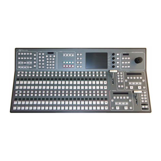
Page 18: Kayak Hd 150C, 200C, 200 Control Panels
Section 2 — Control Surfaces Kayak HD 150C, 200C, 200 Control Panels Figure 5. Kayak HD 150C, 200C, and 200 Control Panel Figure 6. 2 M/E Control Panel, Rear View PS/2 Port USB #4 P/S 2 (Future use) (Future use) -
Page 19: Dimensions
Kayak HD Control Panels Dimensions Figure 7. Kayak HD 150C, 200C, and 200 Control Panels Dimensions 1 of 2 418 mm 16.46 in. 260 mm 10.23 in. 16 mm 65 mm 0.60 in. 2.55 in. 34 mm 1.31 in. 81 mm 3.19 in. - Page 20 Section 2 — Control Surfaces Figure 8. Kayak HD 150C, 200C, and 200 Control Panel Dimensions 2 of 2 Front view 10 mm 10 mm 789 mm 0.39 in. 31.1 in. 0.39 in. 809 mm 31.9 in. 418 mm Top view 16.5 in.
-
Page 21: Kayak Hd 250C, 250, 300 Control Panels
Kayak HD Control Panels Kayak HD 250C, 250, 300 Control Panels Figure 9. Kayak HD 250C, 250, and 300 Control Panel Figure 10. 3 M/E Control Panel, Rear View KAYAK DIGITAL PRODUCTION SWITCHER DC POWER IN RED. DC POWER IN... -
Page 22: Dimensions
Section 2 — Control Surfaces Dimensions Figure 11. Kayak HD 250C, 250, and 300 Control Panels Dimensions 65 mm 2.54 in. 20° 34 mm 7° 1.31 in. 97 mm 3.79 in. Left side view 524 mm 20.63 in. 10 mm 10 mm 0.39 in. -
Page 23: Panel Mounting Options
Kayak HD Control Panels Panel Mounting Options Kayak HD control panels may be placed on a table or similar stable surface, or they may be recessed into a control console in an appropriately sized cutout. Table Top Use High-friction feet prevent inadvertent movement of the panel. The panel is ventilated at its sides. - Page 24 Section 2 — Control Surfaces Figure 12. Kayak HD Panel Mounting Holes 5 mm (0.2 in.) panel edge to centerline of threaded hole Kayak HD — Installation Planning Guide...
-
Page 25: Section 3 - Frames
Kayak video processor chassis. Do not place the air intake side of the Kayak chassis near the air output of another piece of equipment if that output exceeds the maximum Operating Temperature specification. Kayak HD — Installation Planning Guide... -
Page 26: Ru Compact Frame
Section 3 — Frames 4 RU Compact Frame Video Processor Frame Installation 4 RU Compact Frame Dimensions Figure 13. Kayak HD 4 RU Frame Dimensions 482 mm 19.0 in. 465 mm 18.31 in. Front view Kayak HD — Installation Planning Guide... - Page 27 4 RU Compact Frame Figure 14. Kayak HD 4 RU Frame Dimensions 442 mm 17.4 in. 541 mm 523 mm 21.29 in. 20.58 in. 37 mm 1.43 in. Top view Kayak HD — Installation Planning Guide...
-
Page 28: Ru Compact Frame Rack Mounting
The front door lifts off vertically and must have suf- ficient clearance room in order to remove it. If you have equipment mounted too close to the Kayak HD 4 RU Compact Frame, you may not be able to remove the door. -
Page 29: Kayak Hd Video Processor 4 Ru Frame
4 RU Compact Frame Kayak HD Video Processor 4 RU Frame Figure 16. Kayak HD 4RU Frame, Front View with Door Removed Top M/E Slot Controller Flash Power Reset 2 USB Bottom M/E Slot M/E 0 (PP) (and 0.5 M/E) -
Page 30: Ru Frame
Section 3 — Frames 8 RU Frame Video Processor Frame Installation 8 RU Frame Dimensions Figure 18. Kayak HD 8 RU Frame Dimensions 1 of 2 483 mm 19.0 in. 465 mm 18.31 in. 166 mm 6.5 in. 355 mm 13.97 in. - Page 31 8 RU Frame Figure 19. Kayak HD 8 RU Frame Dimensions 2 of 2 Cable Support Wires Top view 541 mm 21.29 in. 523 mm 20.58 in. 37 mm 1.43 in. 442 mm 17.4 in. Kayak HD — Installation Planning Guide...
-
Page 32: Ru Frame Rack Mounting
Additional support, like the rear rack support or slide rails, is required for mobile applications. The Rear Rack support provides additional support and stability for the Kayak HD frame to ensure that it remains horizontal. Kayak HD — Installation Planning Guide... - Page 33 There are air intake holes on the right side of the frame (as you face the frame front) and air exhaust holes on the left. CAUTION A minimum vertical clearance of 7.62 mm (0.3-in.) above the Kayak HD 8 RU frame door is required to remove the door. When installing the Kayak HD 8 RU frame in the rack, take care to leave room for removal of the front door.
- Page 34 Section 3 — Frames Figure 22. Kayak HD 8RU Frame, Backplane View Video In Video Out GPI In 1-8 GPI In 9-16 1 M/E: 1-24 1 M/E: 1-12 GPI Out 1-32 GPI Out 33-64 (Internal Switch 2 M/E: 1-48 2 M/E: 1-24...
-
Page 35: Cabling
The Kayak HD system uses Ethernet, serial, and USB connections. Tally and GPI I/O (General Purpose Interface Input/Output) control are also available. A simple Kayak HD system consisting of a Control Panel and Video Processor frame does not require connection to an external Ethernet Local Area Network (LAN). -
Page 36: Kayak Hd 150C, 200C, And 200 Panel Control Cabling
Control Panel Power Supplies The Kayak HD 150C, 200C, or 200 system uses Ethernet, serial, and USB connections. Tally and GPI/O control are also available. A simple Kayak HD 100C system consisting of a Control Panel and Video Processor frame uses point-to-point connections and does not require connection to an external Ethernet Local Area Network (LAN). -
Page 37: Network Cabling
Managed capability. CAUTION An existing facility Ethernet switch (not hub) can support Kayak HD if an ade- quate number of ports are available. Keep your facility network and technical network separate in order to avoid network traffic negatively affecting Kayak HD system operation. -
Page 38: Factory Network Settings
Note In order to integrate Kayak HD devices into an existing network, ask the local network administrator for the subnet mask of the network. Before changing IP addresses always set the subnet masks of the Kayak HD devices to the mask of the local network. -
Page 39: Outputs
There are two separate, looping reference input pairs. The upper pair accepts analog 525 or 625 composite video. Burst is not required, but typi- cally facility reference color black is used. Kayak HD can auto-sense whether the reference is 525 or 625 and can change the internal standard accordingly. - Page 40 Section 3 — Frames Kayak HD — Installation Planning Guide...
-
Page 41: Section 4 - Options
Section Options KHD-PSU Internal Redundant Power Supply Option This option provides redundant power for the Kayak HD video processor chassis and control panel. It slides into an extra power supply slot in the video processor chassis. Figure 25. KHD-PSU Internal Redundant Power Supply Option... -
Page 42: Kdd-Psu Power Supply Option
Figure 27 on page 43. It features a wide range AC power supply providing power for a remotely-mounted Kayak HD Control Panel or for each additional Control Panel connected to the same processor chassis. Power output is sufficient for two 1 M/E systems or one 2 M/E system. -
Page 43: Installation
KHD-PSU Internal Redundant Power Supply Option Installation Figure 27. KDD-PSU Rack Installation Cut fastening metal so that the ventilation openings are not covered Kayak HD — Installation Planning Guide... -
Page 44: Pin Assignments
There is an RS232 serial port, a keyboard port, and a VGA video output located on front of the Controller Board. These ports are used for diagnos- tics. If you need to use these ports to diagnose problems with the Kayak HD switcher, please contact your Grass Valley Customer Service Representa- tive. -
Page 45: Gpi / Tally Connections
Pin 3 GPI / Tally Connections The Kayak HD GPI / Tally system has universal relays that interface source tally and GPI Output information to an external system through the Tally Port connectors. The channels can be assigned in the Setup menu. -
Page 46: Gpi Inputs
There are two 50 pin female subminiature 'D' connectors on the rear of the 4 RU Kayak HD frame and four connectors on the rear of the 8 RU Kayak HD frame. Each connector is activated by the presence of a Mix/Effects module installed in the frame. -
Page 47: Gpi Input Structure
The function of each GPI input is user assignable. The activation of the function can be programmed to occur on the leading edge or the trailing edge of the closure, or both edges. The switch must be closed for at least one field. Kayak HD — Installation Planning Guide... -
Page 48: Gpi / Tally Outputs
Section 4 — Options Refer to the Install Menus section of the Kayak HD User Manual for details on setting the input signal activating edge. Refer to the Configuration Menu section of the Kayak HD User Manual for details on setting the function of a GPI input. - Page 49 27G of 32 28G of 32 Common G 12V Lamp 29H of 32 30H of 32 12V Lamp 31H of 32 32H of 32 + 12V DC Common H Kayak HD Frame User Equipment Kayak HD — Installation Planning Guide...
- Page 50 Each output can be programmed for function, steady state or pulse, output polarity, and pulse duration. Refer to the Install Menus section of the Kayak HD User Manual for details on setting the characteristics of the output signal (steady state, polarity, pulse duration, etc.). Refer to the...
- Page 51 Pin 50 GPIOut6B GPIOut7B GPIOut8B GPIOutComC GPIOut9C GPIOut10C GPIOut11C GPIOut12C GPIOutComD GPIOut13D GPIOut14D GPIOut15D GPIOut16D GPIOutComE GPIOut17E GPIOut18E GPIOut19E GPIOut20E GPIOutComF GPIOut21F GPIOut22F GPIOut23F GPIOut24F GPIOutComG GPIOut25G GPIOut26G GPIOut27G GPIOut28G GPIOutComH GPIOut29H GPIOut30H GPIOut31H GPIOut32H Kayak HD — Installation Planning Guide...
- Page 52 Pin 50 GPIOut38K GPIOut39K GPIOut40K GPIOutComL GPIOut41L GPIOut42L GPIOut43L GPIOut44L GPIOutComM GPIOut45M GPIOut46M GPIOut47M GPIOut48M GPIOutComN GPIOut49N GPIOut50N GPIOut51N GPIOut52N GPIOutComP GPIOut53P GPIOut54P GPIOut55P GPIOut56P GPIOutComQ GPIOut57Q GPIOut58Q GPIOut59Q GPIOut60Q GPIOutComR GPIOut61R GPIOut62R GPIOut63R GPIOut64R Kayak HD — Installation Planning Guide...
- Page 53 Pin 50 GPIOut70T GPIOut71T GPIOut72T GPIOutComU GPIOut73U GPIOut74U GPIOut75U GPIOut76U GPIOutComV GPIOut77V GPIOut78V GPIOut79V GPIOut80V GPIOutComW GPIOut81W GPIOut82W GPIOut83W GPIOut84W GPIOutComX GPIOut85X GPIOut86X GPIOut87X GPIOut88X GPIOutComY GPIOut89Y GPIOut90Y GPIOut91Y GPIOut92Y GPIOutComZ GPIOut93Z GPIOut94Z GPIOut95Z GPIOut96Z Kayak HD — Installation Planning Guide...
- Page 54 Pin 50 GPIOut102AB GPIOut103AB GPIOut104AB GPIOutComAC GPIOut105AC GPIOut106AC GPIOut107AC GPIOut108AC GPIOutComAD GPIOut109AD GPIOut110AD GPIOut111AD GPIOut112AD GPIOutComAE GPIOut113AE GPIOut114AE GPIOut115AE GPIOut116AE GPIOutComAF GPIOut117AF GPIOut118AF GPIOut119AF GPIOut120AF GPIOutComAG GPIOut121AG GPIOut122AG GPIOut123AG GPIOut124AG GPIOutComAH GPIOut125AH GPIOut126AH GPIOut127AH GPIOut128AH Kayak HD — Installation Planning Guide...
- Page 55 Hubs 150C, 200C, and 200, Dimensions Ethernet 250C, 250, and 300 Dimensions Control Cabling Control Protocols Inputs Supported Reference Video Cabling Installation Dimensions 8 RU Video Processor 100C Control Panel KDD-PSU Power Supply Option Kayak HD — Installation Planning Guide...
- Page 56 Network Cabling software download from web Switcher Models Systems Specifications Video Cabling Standard Features Kayak HD 250C, 250, 300 Control Panels Kayak HD Kayak HD Control Panels Supported Control Protocols KDD-PSU Surface Mount Cutout Dimensions Power Supply Option Switcher Models...
- Page 57 Index Zodiak Kayak HD — Installation Planning Guide...
- Page 58 Index Kayak HD — Installation Planning Guide...
Need help?
Do you have a question about the Kayak HD and is the answer not in the manual?
Questions and answers