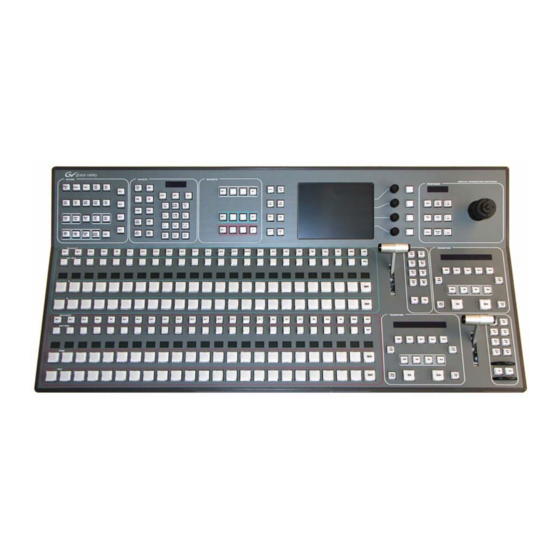
GRASS VALLEY Kayak HD Installation And Service Manual
Digital production switcher
Hide thumbs
Also See for Kayak HD:
- Installation and service manual (186 pages) ,
- Installation planning manual (60 pages) ,
- Datasheet (8 pages)

Related Manuals for GRASS VALLEY Kayak HD


Summary of Contents for GRASS VALLEY Kayak HD
- Page 1 Kayak HD DIGITAL PRODUCTION SWITCHER Installation and Service Manual Software Version 6.9.4 071844808 MAY 2011...
- Page 2 CERTIFICATE Certificate Number: 510040.001 The Quality System of: Grass Valley USA, LLC and its Grass Valley Affiliates Headquarters: 400 Providence Mine Road 15655 SW Greystone Ct. Brunnenweg 9 Nevada City, CA 95945 Beaverton, OR 97006 D-64331 Weiterstadt United States United States...
- Page 3 Kayak HD DIGITAL PRODUCTION SWITCHER Installation and Service Manual Software Version 6.9.4 071844808 MAY 2011...
- Page 4 Benelux/Belgium: +32 (0) 2 334 90 30 Benelux/Netherlands: +31 (0) 35 62 38 42 1 N. Europe: +45 45 96 88 70 Germany, Austria, Eastern Europe: +49 6150 104 444 UK, Ireland, Israel: +44 118 923 0499 Copyright © Grass Valley USA, LLC. All rights reserved. This product may be covered by one or more U.S. and foreign patents.
-
Page 5: Table Of Contents
Kayak HD Video Processor Frames ........ - Page 6 4 RU Compact Frame Rack Mounting........Kayak HD Video Processor 4 RU Frame....... .
- Page 7 Reset / Check / Clear Device Menu ....... . . Kayak HD — Installation and Service Manual...
- Page 8 Changing the Batteries..........Change the Kayak HD Frame Battery ....... . .
- Page 9 ..............Kayak HD — Installation and Service Manual...
- Page 10 Contents Kayak HD — Installation and Service Manual...
-
Page 11: Preface
The User Manual contains background information about the Kayak HD Digital Production switcher and describes operating procedures. This manual can be used while learning about Kayak HD and for enhancing your basic knowledge of the system. The Installation and Service Manual contains information about installing, configuring, and maintaining the system. - Page 12 Preface Kayak HD — Installation and Service Manual...
-
Page 13: Regulatory Notices
Changes or modifications not expressly approved by Grass Valley Group can affect emission compliance and could void the user’s authority to operate this equipment. -
Page 14: Canadian Certified Power Cords
Part 1: General Requirements”, (CAN/CSA-C22.2 No. 60950-1-03. First Edition Dated April 1, 2003, with revisions through and including November 26, 2003) EN60950 Safety of Information Technology Equipment, including Electrical Busi- ness Equipment. 73/23/EEC Low Voltage Directive Kayak HD — Installation and Service Manual... - Page 15 Annex A - Radiated Magnetic Field Immunity Note: This only applies to assemblies sensitive to magnetic fields US FCC Class A CISPR Pub. 22 (1985) Canada FCC Industry Canada Australia & AS/NZS 3548 New Zealand: Kayak HD — Installation and Service Manual...
- Page 16 Regulatory Notices Kayak HD — Installation and Service Manual...
-
Page 17: Safety Summary
DANGER the marking. — A personal injury hazard exists but is not immediately acces- WARNING sible as you read the marking. — A hazard to property, product, and other equipment is present. CAUTION Kayak HD — Installation and Service Manual... -
Page 18: Symbols On The Product
— Do not internally service this product unless another Do not service alone person capable of rendering first aid and resuscitation is present. — Prior to servicing, remove jewelry such as rings, watches, Remove jewelry and other metallic objects. Kayak HD — Installation and Service Manual... -
Page 19: Cautions
— To prevent product overheating, provide equip- Provide proper ventilation ment ventilation in accordance with installation instructions. Kayak HD — Installation and Service Manual... - Page 20 (ASICS). As a result, circuit board repair at the component level is very difficult in the field, if not impossible. For war- ranty compliance, do not troubleshoot systems beyond the board level. Kayak HD — Installation and Service Manual...
-
Page 21: Section 1 - System Overview
• Kayak HD or SD 200C, which includes a 2 M/E Control Panel and a 4 RU Video Processor frame equipped with two M/E modules • Kayak HD or SD 200, which includes a 2 M/E Control Panel and a 8 RU Video Processor frame equipped with two M/E modules •... -
Page 22: Kayak Hd Standard Features
Frame-only models are available for the configurations listed above and include the following: • Kayak HD or SD 350 Frame-only which includes an 8 RU Video Pro- cessor frame equipped with three mix/effects and the license for a Half • Kayak HD or SD 400 Frame-only which includes an 8 RU Video Pro- cessor frame equipped with four mix/effects •... - Page 23 Introduction • Number of inputs: • 24 to 48 for Kayak HD 100C, 150C • 48 for Kayak HD 200C, 250C • 48 to 96 for Kayak HD 200, 250 • 72 to 96 for Kayak HD 300, 350 • 96 for Kayak HD 400, 450 •...
-
Page 24: Kayak Hd Options
• Adds four DSKs for up to 20 keyers for 4.5 M/Es in the 8RU frame • Adds four DSKs for up to 12 keyers in the 4RU frame • Or Half M/E Mode with A/B background mix and four Lin/Lum keyers Kayak HD — Installation and Service Manual... -
Page 25: Supported Control Protocols
Fits in any available M/E slot. • Full M/E Upgrade Option. Adds one Mix/Effects module to any Kayak HD chassis. Order one or more options to get the total M/Es required. The 4RU chassis holds up to two M/E modules and/or I/O Expander modules. -
Page 26: System Components
System Components Kayak HD Control Surfaces Kayak HD Production Switcher systems use a control panel with an inte- grated menu display (color TFT with touch-screen). The Sidepanel pro- gram, which runs on a user-supplied Windows PC, can also be used to control the Kayak HD system. -
Page 27: 1.5 And 2 M/E Control Panel
System Components 1.5 and 2 M/E Control Panel Figure 3. Kayak HD 150C, 200C, and 200 Control Panel Figure 4. 2 M/E Control Panel, Rear View PS/2 Port USB #4 P/S 2 (Future use) (Future use) 48V DC Power In... -
Page 28: 2.5 And 3M/E Control Panel
Section 1 — System Overview 2.5 and 3M/E Control Panel Figure 5. Kayak HD 250C, 250, and 300 Control Panel Figure 6. 3 M/E Control Panel, Rear View KAYAK DIGITAL PRODUCTION SWITCHER DC POWER IN RED. DC POWER IN RS 232 RS 485 48V/1.3A max. -
Page 29: Kayak Hd Video Processor Frames
System Components Kayak HD Video Processor Frames Kayak 4 RU Frame Figure 7. Kayak HD 4RU Frame, Front View with Door Removed Top M/E Slot Controller Flash Power Reset 2 USB Bottom M/E Slot M/E 0 (PP) (and 0.5 M/E) -
Page 30: Kayak 8 Ru Frame
Section 1 — System Overview Kayak 8 RU Frame Figure 8. Kayak HD 8RU Frame, Front View with Door Removed Fan Assembly Flash Power Reset RS-232 2 USB Air Filter Memory Switch Button Keyboard (unused) M/E 0 (PP) M/E 1 Controller (and 0.5 M/E) -
Page 31: Kdd-Psu Power Supply Option
KDD-PSU Power Supply Option The KDD-PSU option is a one-rack unit, wide range AC power supply pro- viding power for a remotely-mounted Kayak HD Control Panel or for each additional Control Panel connected to the same processor chassis. Power output is sufficient for two 1 M/E systems or one 2 M/E system. -
Page 32: Video Signal Flow
The AUX bus outputs can be utilized in a number of ways. Every AUX bus provides individually adjustable safe area and crosshair (center cross) capability. Each AUX bus is timed to the reference. Kayak HD — Installation and Service Manual... - Page 33 Video Signal Flow Figure 11. Kayak HD Video Signal Flow Main Board Crosspoint 144 x 144 M/E 1 Mix Effect Board Variable Delay Video Proc Σ Variable Delay Σ Video Proc Variable Delay Video Proc Σ Variable Delay Video Proc Σ...
- Page 34 Section 1 — System Overview Kayak HD — Installation and Service Manual...
-
Page 35: Section 2 - Installation
Section Installation Pre-Installation Procedures Before you physically install the Kayak HD system, familiarize yourself with the tools required, physical specifications, and safety and power requirements covered in this section. System Survey Check all parts received against the packing list enclosed with your ship- ment, and examine the equipment for any shipping damage. -
Page 36: Safety Requirements
CAUTION To avoid static damage to sensitive electronic devices, protect the Kayak HD system from static discharge. Avoid handling frame modules in a high static environment. -
Page 37: General Rack Mounting Instructions
(leakage) currents for all power supplies does not exceed 3.5 mA. 4 RU Frame Video Processor Frame Installation 4 RU Compact Frame Dimensions Figure 12. Kayak HD 4 RU Frame Dimensions 482 mm 19.0 in. 465 mm 18.31 in. - Page 38 Section 2 — Installation Figure 13. Kayak HD 4 RU Frame Dimensions 442 mm 17.4 in. 541 mm 523 mm 21.29 in. 20.58 in. 37 mm 1.43 in. Top view Kayak HD — Installation and Service Manual...
-
Page 39: Ru Compact Frame Rack Mounting
The front door lifts off vertically and must have suf- ficient clearance room in order to remove it. If you have equipment mounted too close to the Kayak HD 4 RU Compact Frame, you may not be able to remove the door. -
Page 40: Kayak Hd Video Processor 4 Ru Frame
Section 2 — Installation Kayak HD Video Processor 4 RU Frame Figure 15. Kayak HD 4RU Frame, Front View with Door Removed Top M/E Slot Controller Flash Power Reset 2 USB Bottom M/E Slot M/E 0 (PP) (and 0.5 M/E) -
Page 41: License Eeproms
You should always keep a copy of your license text file or you may lose all features, including Inputs, chroma keys, and DPMs. If you have lost your license, contact Customer Service. (See Contacting Grass Valley on page Kayak HD — Installation and Service Manual... -
Page 42: Ru Frame
Section 2 — Installation 8 RU Frame Video Processor Frame Installation 8 RU Frame Dimensions Figure 18. Kayak HD 8 RU Frame Dimensions 1 of 2 483 mm 19.0 in. 465 mm 18.31 in. 166 mm 6.5 in. 355 mm 13.97 in. - Page 43 8 RU Frame Figure 19. Kayak HD 8 RU Frame Dimensions 2 of 2 Cable Support Wires Top view 541 mm 21.29 in. 523 mm 20.58 in. 37 mm 1.43 in. 442 mm 17.4 in. Kayak HD — Installation and Service Manual...
-
Page 44: Ru Frame Rack Mounting
Additional support, like the rear rack support or slide rails, is required for mobile applications. The Rear Rack support provides additional support and stability for the Kayak HD frame to ensure that it remains horizontal. Kayak HD — Installation and Service Manual... - Page 45 There are air intake holes on the right side of the frame (as you face the frame front) and air exhaust holes on the left. CAUTION A minimum vertical clearance of 7.62 mm (0.3-in.) above the Kayak HD 8 RU frame door is required to remove the door. When installing the Kayak HD 8 RU frame in the rack, take care to leave room for removal of the front door.
- Page 46 Section 2 — Installation Figure 22. Kayak HD 8RU Frame, Backplane View Video In Video Out GPI In 1-8 GPI In 9-16 1 M/E: 1-24 1 M/E: 1-12 GPI Out 1-32 GPI Out 33-64 (Internal Switch 2 M/E: 1-48 2 M/E: 1-24...
-
Page 47: Kayak Hd Frame Connectors
Additionally the 8V DC voltage for RAM Recorder buffering can be sup- plied via this socket. DC POWER OUT Output connector for Panel DC Power Supply. (High current D-Sub, male). Output voltage: 48V/ 1.6A max. A 10m DC power connecting cable is supplied. Kayak HD — Installation and Service Manual... -
Page 48: Internal Redundant Power Supply Option
The front door lifts off vertically and must have suf- ficient clearance room in order to remove it. If you have equipment mounted too close to the Kayak HD 4 RU Compact Frame, you may not be able to remove the door. - Page 49 Removing and Replacing the Kayak HD Frame Door To remove the Kayak HD frame door: 1. Turn the lock on the front door of the Kayak HD Frame 180-degrees counterclockwise to unlock it. 2. Open the door to less than 90-degrees from the Frame.
-
Page 50: Control Panel Installation
Section 2 — Installation Control Panel Installation 1 M/E Control Panel Figure 25. Kayak HD 100C Control Panel Dimensions 1 of 2 418 mm 16.46 in. 260 mm 10.23 in. 66 mm 2.55 in. 16 mm 0.60 in. 34 mm 81 mm 1.31 in. - Page 51 Control Panel Installation Figure 26. Kayak HD 100C Control Panel Dimensions 2 of 2 Front view 10 mm 428 mm 10 mm 0.39 in. 16.85 in. 0.39 in. 448 mm 17.64 in. 418 mm 16.5 in. Top view 448 mm 17.64 in.
-
Page 52: 2 M/E Control Panel
Section 2 — Installation 2 M/E Control Panel Figure 27. Kayak HD 150C and 200C Control Panel Dimensions 1 of 2 418 mm 16.46 in. 260 mm 10.23 in. 16 mm 65 mm 0.60 in. 2.55 in. 34 mm 1.31 in. - Page 53 Control Panel Installation Figure 28. Kayak HD 150C, 200C, and 200 Control Panel Dimensions 2 of 2 Front view 10 mm 10 mm 789 mm 0.39 in. 31.1 in. 0.39 in. 809 mm 31.9 in. 418 mm Top view 16.5 in.
-
Page 54: 3M/E Control Panel
Section 2 — Installation 3M/E Control Panel Figure 29. Kayak HD 250C, 250, and 300 Control Panel Dimensions 65 mm 2.54 in. 20° 34 mm 7° 1.31 in. 97 mm 3.79 in. Left side view 524 mm 20.63 in. 10 mm 10 mm 0.39 in. -
Page 55: Panel Mounting Options
Control Panel Installation Panel Mounting Options Kayak HD control panels may be placed on a table or similar stable surface, or they may be recessed into a control console in an appropriately sized cutout. Table Top Use High-friction feet prevent inadvertent movement of the panel. The panel is ventilated at its sides. -
Page 56: Securing Panels To Mounting Surface
(two each on the left and right side of the panel) are available for securing the panel in the cutout (Figure 30). Figure 30. Kayak HD Panel Mounting Holes 5 mm (0.2 in.) panel edge to centerline of threaded hole... -
Page 57: Kayak Hd Control Panel Connectors
USB flash drive refer to the section on Recommended USB Flash Drives in the Kayak Release Notes. Only recommended devices are supported. P/S 2 Used to connect a P/S 2 Mouse or Keyboard. Figure 32. Kayak HD Connectors Top Rear Control Panel Kayak HD — Installation and Service Manual... -
Page 58: Kdd-Psu Power Supply Option
12V ... 24V DC 12V DC OUT For future use J4, J5 DC POWER Two output connectors for DC Power Supply. (High current D-Sub, male). Output voltage: 48V/ total 6A max Ground Terminal Terminal for grounding. Kayak HD — Installation and Service Manual... -
Page 59: Pin Assignments
There is an RS232 serial port, a keyboard port, and a VGA video output located on front of the Controller Board. These ports are used for diagnos- tics. If you need to use these ports to diagnose problems with the Kayak HD switcher, please contact your Grass Valley Customer Service Representa- tive. -
Page 60: Gpi / Tally Connections
Pin 3 GPI / Tally Connections The Kayak HD GPI / Tally system has universal relays that interface source tally and GPI Output information to an external system through the Tally Port connectors. The channels can be assigned in the Setup menu. -
Page 61: Kayak Hd Gpi And Tally Interface
There are two 50 pin female subminiature 'D' connectors on the rear of the 4 RU Kayak HD frame and four connectors on the rear of the 8 RU Kayak HD frame. Each connector is activated by the presence of a Mix/Effects module installed in the frame. -
Page 62: Gpi Input Structure
Kayak HD Frame Pins 1 and 34 of each of the two (four) connectors are connected to ground. For applications that span across more than one connector, only one ground (common) connection is required. Kayak HD — Installation and Service Manual... -
Page 63: Gpi / Tally Outputs
The switch must be closed for at least one field. Refer to the Install Menus section of the Kayak HD User Manual for details on setting the input signal activating edge. Refer to the Configuration Menu section of the Kayak HD User Manual for details on setting the function of a GPI input. - Page 64 27G of 32 28G of 32 Common G 12V Lamp 29H of 32 30H of 32 12V Lamp 31H of 32 32H of 32 + 12V DC Common H Kayak HD Frame User Equipment Kayak HD — Installation and Service Manual...
- Page 65 Each output can be programmed for function, steady state or pulse, output polarity, and pulse duration. Install Menus section of the Kayak HD User Manual for details Refer to the on setting the characteristics of the output signal (steady state, polarity, pulse duration, etc.).
- Page 66 GPIOut6B GPIOut7B GPIOut8B GPIOutComC GPIOut9C GPIOut10C GPIOut11C GPIOut12C GPIOutComD GPIOut13D GPIOut14D GPIOut15D GPIOut16D GPIOutComE GPIOut17E GPIOut18E GPIOut19E GPIOut20E GPIOutComF GPIOut21F GPIOut22F GPIOut23F GPIOut24F GPIOutComG GPIOut25G GPIOut26G GPIOut27G GPIOut28G GPIOutComH GPIOut29H GPIOut30H GPIOut31H GPIOut32H Kayak HD — Installation and Service Manual...
- Page 67 GPIOut38K GPIOut39K GPIOut40K GPIOutComL GPIOut41L GPIOut42L GPIOut43L GPIOut44L GPIOutComM GPIOut45M GPIOut46M GPIOut47M GPIOut48M GPIOutComN GPIOut49N GPIOut50N GPIOut51N GPIOut52N GPIOutComP GPIOut53P GPIOut54P GPIOut55P GPIOut56P GPIOutComQ GPIOut57Q GPIOut58Q GPIOut59Q GPIOut60Q GPIOutComR GPIOut61R GPIOut62R GPIOut63R GPIOut64R Kayak HD — Installation and Service Manual...
- Page 68 GPIOut70T GPIOut71T GPIOut72T GPIOutComU GPIOut73U GPIOut74U GPIOut75U GPIOut76U GPIOutComV GPIOut77V GPIOut78V GPIOut79V GPIOut80V GPIOutComW GPIOut81W GPIOut82W GPIOut83W GPIOut84W GPIOutComX GPIOut85X GPIOut86X GPIOut87X GPIOut88X GPIOutComY GPIOut89Y GPIOut90Y GPIOut91Y GPIOut92Y GPIOutComZ GPIOut93Z GPIOut94Z GPIOut95Z GPIOut96Z Kayak HD — Installation and Service Manual...
- Page 69 GPIOut102AB GPIOut103AB GPIOut104AB GPIOutComAC GPIOut105AC GPIOut106AC GPIOut107AC GPIOut108AC GPIOutComAD GPIOut109AD GPIOut110AD GPIOut111AD GPIOut112AD GPIOutComAE GPIOut113AE GPIOut114AE GPIOut115AE GPIOut116AE GPIOutComAF GPIOut117AF GPIOut118AF GPIOut119AF GPIOut120AF GPIOutComAG GPIOut121AG GPIOut122AG GPIOut123AG GPIOut124AG GPIOutComAH GPIOut125AH GPIOut126AH GPIOut127AH GPIOut128AH Kayak HD — Installation and Service Manual...
-
Page 70: Cabling Overview
The Kayak HD system uses Ethernet, serial, and USB connections. Tally and GPI I/O (General Purpose Interface Input/Output) control are also available. A simple Kayak HD system consisting of a Control Panel and Video Processor frame does not require connection to an external Ethernet Local Area Network (LAN). -
Page 71: Kayak Hd 150C, 200C,And 200 Control Cabling
Be sure to power down before installing the mouse. Ethernet Switches and Hubs A Kayak HD system requires a LAN when components other than a Control Panel and Video Processor frame are connected, or when external network access to a file system is desired. An appropriately-sized Ethernet switch may be required. - Page 72 Managed capability. CAUTION An existing facility Ethernet switch (not hub) can support Kayak HD if an ade- quate number of ports are available. Keep your facility network and technical network separate in order to avoid network traffic negatively affecting Kayak HD system operation.
-
Page 73: Factory Network Settings
Network Settings - Telnet on page Note In order to integrate Kayak HD devices into an existing network, ask the local network administrator for the subnet mask of the network. Before changing IP addresses always set the subnet masks of the Kayak HD devices to the mask of the local network. -
Page 74: Outputs
Kayak HD Video Timing Kayak HD Home - Install Menu 1. To begin setting the Video Timing for the Kayak HD switcher press the Home key on the switcher control panel to go to the menu on the Home Kayak HD switcher menu screen. - Page 75 E-Box Genlock Genlock Genlock menu reports the status of the Kayak HD system sync generator. It is used to switch between HD and SD operating modes and to adjust the internal system timing. Figure 40. Genlock Menu with Video Signal in Green Legal Timing Window...
- Page 76 NONE Note The Kayak HD cannot support both SD and HD at the same time; you must choose one mode or the other. If you change the mode from SD to HD (or vice versa) then the Kayak HD hardware must reprogram itself to process the change.
-
Page 77: Select The Video Standard
HD Auto Detect, but a different video standard may be selected on your switcher.) Figure 41. Select Video Standard Menu 2. Press to select the video standard you wish to use for the Kayak HD switcher. If you select either the Kayak HD... -
Page 78: Select The Video Reference Source
1. At the top right of the menu press the button shown in the Genlock HD Ref data pad. The Input menu displays a scrolling list Select HD Reference of HD Reference Inputs from which to choose. Kayak HD — Installation and Service Manual... - Page 79 2. Press on the arrows to scroll through the list. Press to select the name of the HD Reference Input signal you want to use. These signals correspond to video inputs associated with the physical inputs on the back of the Kayak HD frame. Kayak HD — Installation and Service Manual...
-
Page 80: Select Sf Mode
Section 2 — Installation Select SF Mode The Kayak HD system supports 1080sf (segmented frame) video formats at 23.9, 24, 25 and 30 fps. Segmented frame video captures a frame of video progressively, but displays the frame as two interlaced fields. -
Page 81: Adjust Internal System Timing
Adjusting the Phase affects the phase of all inputs and outputs of the switcher with respect to the external reference. Grass Valley recommends that you use the AUX1 bus to check the video timing of all inputs. This compares the video source selected on the AUX1 bus to the switcher’s internal system timing. - Page 82 Genlock menu is not displayed, press the E-Box button and select Genlock. 4. On the Kayak HD control panel press a key to select a video source from the AUX 1 bus. You need to check all video sources for timing.
- Page 83 AUX1 bus. Select all video sources and record their Phase number. 8. Find the average Phase value by adding the highest and the lower Phase numbers together and then divide by two. Figure 48. Genlock Menu with Illegal Timing Source Kayak HD — Installation and Service Manual...
- Page 84 Note If you add additional M/Es to your switcher you must also recalibrate your video timing to make sure all sources are within the new smaller green legal timing window. Kayak HD — Installation and Service Manual...
-
Page 85: Main Panel Adjustments
1. Move all faders to the upper position and press 2. Move all faders to the lower position and press The data pad will indicate that the Status is when done. adjusted Kayak HD — Installation and Service Manual... -
Page 86: Joystick Calibration
Touch Screen Calibration call up the Touchscreen Calibration data pad. Once you can see the Touch- screen Calibration data pad you should be able to perform the calibration procedure using your finger or a stylus. Kayak HD — Installation and Service Manual... -
Page 87: Kayak System Control Via Pc
LINK/ACTIVITY OFF-10 AMBER-100 GREEN-1000 Supplied CAT5 Cable Configure your computer to connect to the Kayak HD by specifying the IP address for your computer using this format: IP Address 192.168.0.xxx Subnet Mask: 255.255.255.0 To set the Identification for your computer and workgroup change your Network Properties to reflect your computer name and workgroup (if required). - Page 88 Section 2 — Installation Kayak HD — Installation and Service Manual...
-
Page 89: Section 3 - Configuration
Configuration Introduction This section provides system configuration information for the Kayak HD Digital Production Switcher. Refer to the latest Kayak HD Release Notes for additional information specific to your current software version. Basic Configuration Steps Kayak HD system configuration includes the following basic steps: 1. -
Page 90: Setting Up Ip Addresses
Section 3 — Configuration Setting Up IP Addresses Network Settings The Kayak HD switcher communicates with other devices over an Ethernet network. When connecting new devices you may wish to configure their network settings. Note If you are experiencing problems with the network settings for your switcher,... - Page 91 Device Control System Device Control with a list of devices connected to the Kayak HD switcher in the left- hand pane. Figure 52. Device Control Menu with Device List 5. Select the device whose IP address you want to configure from the device list by touching the name.
-
Page 92: Netmask
Netmask setting you want to use for the device you selected. Network Settings - Telnet Another way to configure network settings for the Kayak HD control panel and frame as well as for connected devices is to connect a computer to the switcher by using Telnet instead of the control panel menus. -
Page 93: Open A Telnet Connection
Setting Up IP Addresses Open a Telnet Connection To set up a Telnet connection for your Kayak HD switcher: 1. Connect a computer terminal to the Kayak frame using a pass-through male-to-female serial cable (do not use a null modem cable) connecting the DB9 connector on the front of the Kayak frame chassis to the communications port on the back of the computer. -
Page 94: Ip Address
(0xFFFFFE00 for address 255.255.254.0) and type in the command: sysSubnetMaskSet 0xFFFFFE00 Note The normal Subnet Mask that ships with the Kayak frame is , which would be in hex. 255.255.255.0 ffffff00 Kayak HD — Installation and Service Manual... -
Page 95: Gateway
Setting Up IP Addresses Gateway CAUTION Resetting the default Gateway address for the Kayak HD frame can cause you to lose all network connections and all switcher functionality. This operation should only be done by a trained engineer. If you lose switcher function you... -
Page 96: Software Installation
Section 3 — Configuration Software Installation Kayak system software updates are distributed on a Kayak Software Release CD-ROM, or can be downloaded from the Thomson Grass Valley web site. Software Versions The currently loaded software versions of the Kayak system devices is shown on the Device Control menu, accessed via Home –... -
Page 97: Software Option Licenses
Refer to the latest Kayak Release Notes for a detailed description of the com- plete software installation procedure. Software Option Licenses Kayak HD has a software option licensing system. You can see the number and type of possible licenses for your system by going to the menu... -
Page 98: Available Options And Configuration Licenses
• RGB Color Correction • DPM Channels • Kurl (Kayak HD/SD only, not KayakDD) • Spektra (Kayak HD/SD only, not KayakDD) • DSK/Half M/E (Kayak HD/SD only, not KayakDD) • NetCentral Note For basic operation licenses are required for Switcher Type, Number of Inputs, and Number of Outputs. -
Page 99: Installing Licenses
E-MEM effects store Source IDs, not the source select buttons, so remapping sources does not change the appearance of recalled effects. Assign Sources To assign a source to a button on the Kayak HD switcher: 1. Press the button on the control panel. - Page 100 56) is the Short IN01 Name of the source. The Short Name is a four-character name that is shown on the Source Name Displays (also called Mnemonic Displays) above the buttons on the control panel. Kayak HD — Installation and Service Manual...
- Page 101 Figure 57. Input Selected for Assignment in Left-Hand Input Pane 6. At the bottom right of the Button pane press the button to assign Assign the Input you selected to the Button you selected. Figure 58. Assign Button at Bottom Right Kayak HD — Installation and Service Manual...
-
Page 102: Rename Sources
Kayak frame. Note Table 10 on page 130 for descriptions of the available internal sources. Rename Sources To rename a source that has already been assigned on the Kayak HD switcher: 1. Press the button on the control panel. Home 2. - Page 103 Button Assignment (Source to Button Mapping) 3. Press . The menu displays. EBox Ebox Configuration Figure 60. Ebox Configuration Menu 4. Press the button. The menu displays. Input Config - Input Figure 61. Config - Input Menu Kayak HD — Installation and Service Manual...
- Page 104 Names are restricted to four characters. Figure 62. Enter Short Input Name Typing Pad Use the keys on the typing pad to type in the Short Name you want to use for your Source and press Kayak HD — Installation and Service Manual...
-
Page 105: Assigning Permanent Sources To Aux Buses
( ) to the Aux bus feeding PVWP PVWH your preview monitor. Use the Install - EBox - AUX menu to assign permanent sources to AUX bus output BNCs. Kayak HD — Installation and Service Manual... -
Page 106: Assigning On-Air Tallies
Section 3 — Configuration Figure 64. Install – AUX Menu Grass Valley recommends that you use upper AUX busses for monitoring purposes. This leaves lower AUX busses free for special purposes, i.e. external DPMs. Note If an AUX bus has been assigned a permanent internal source selection the main control panel for that AUX bus is locked out. -
Page 107: Save Installation And Configuration Settings
USB stick, however. If you want to keep multiple sets you will need to save them directly onto a dif- ferent USB sticks, or copy these files to a separate computer. Kayak HD — Installation and Service Manual... -
Page 108: Save All Install Data
USB present containing Install data will Load load that data to the Kayak system. A reset will be required to activate the new settings. Note The Sidepanel program identifies the Install data as Global settings. Kayak HD — Installation and Service Manual... -
Page 109: Save Panel Install Data
The last set of environment data loaded will be used by the system. Save Application Data All setting in the Config menu hierarchy, and other operational settings (E-MEMs, etc.) are saved and loaded separately as Applications via the Config - Application Control menu (Figure 67). Kayak HD — Installation and Service Manual... -
Page 110: Panel Lock
Load Panel Lock Locking The Panel Once you have configured the Kayak HD you may want to lock the panel to prevent accidental or unauthorized changes to control adjustments or settings. Kayak HD — Installation and Service Manual... - Page 111 Locked The panel cannot be detached. When the panel is locked, the attached side panel is also locked. To lock the Kayak HD control panel in DD Mode (Figure 68): 1. Press and hold the button...
-
Page 112: Unlocking The Panel
Section 3 — Configuration Figure 69. Locking the Panel from the Effects Button Section in Default Mode Unlocking The Panel To unlock the Kayak HD control panel: 1. DD Mode: Press and hold the button along with the button TransDur Store in the Effects button section of the panel. -
Page 113: Install Menus Reference
Figure In the following sections the most important Install menus are described. Once you understand the principles of Kayak HD system menu organiza- tion and operation, you will be able to quickly learn these new menus and use them effectively for your work. -
Page 114: Install - Genlock Menu
Figure 71. Install - Genlock Menu menu reports the status of the sync regenerator of the Install- Genlock Kayak HD system, and is used to switch between HD and SD operating modes and adjust input timing. The selected video standard is reported in the field. - Page 115 Install Menus Reference Figure 72. Install – Select Video Standard Kayak HD — Installation and Service Manual...
-
Page 116: Selecting The Video Reference Source
Figure 73. Install – Select Reference Input Analog Reference signal connected with jack HD Analog ANALOG Used for synchronizing the switcher. REFERENCE Selected input source is used for synchronizing the IN 01 … IN24 switcher Kayak HD — Installation and Service Manual... -
Page 117: Install - Editor Menu
Install Menus Reference Install - Editor Menu Basic editor control of the Kayak HD system is supported. Capabilities include: Source selection, Key selection, Wipe selection, Preview, Timeline control (Jog/Go to Time, Run, Rewind), Transition Mode, Rate, and Trig- gers, All Stop, E-MEM. - Page 118 Special Editor Protocol BVE-2000 Options 1. Wipe Mapping: “GVG Pattern Numbers”, “XtenDD Pattern Numbers” 2. DSK Support: “BVE2000”, “default” 3. DSK Mapping: “to Key4”, “to Key3” Default settings are underlined. Figure 75. Install - Editor Options Menu Kayak HD — Installation and Service Manual...
- Page 119 Audio Fader 4 Video Input 6 Audio Fader 3 Video Input 7 Audio Fader 2 Video Input 8 Audio Fader 1 Video Input 9 Audio Fader 16 Video Input 10 Audio Fader 15 Kayak HD — Installation and Service Manual...
-
Page 120: Install - Gpi Menu
Install - GPI Menu GPI Inputs can be used by an external device to trigger an action on the Kayak HD system. See Installation Manual for pinout specifications. The GPI In menu allows programming up to 32 system GPI inputs. Various actions can be performed when a GPI contact closes, including selecting a source on a bus, recalling an E-MEM, and triggering a transition. -
Page 121: Install - Gpo Menu
Install Menus Reference Install - GPO Menu GPO Output contact closures are used by the Kayak HD system for simple trigger control of external devices. See Installation Manual for pinout and voltage specifications. In this Install-GPO menu the physical properties of up to 128 GPO channels can be adjusted. -
Page 122: Install - Misc Menu
USB port. The Load button is grayed out if no USB stick is present of if no files are available to load from the USB stick. USB ports labeled SPARE are not supported. Kayak HD — Installation and Service Manual... -
Page 123: Install - Machine Control Menu
• For some remote protocols configuration options are selectable (all GVG200 based protocols, AMP, Odetics, VDCP, BVW75). The options can be selected by pressing the button (see details Select Options below). • Select option and change value by pressing the button. Modify Kayak HD — Installation and Service Manual... - Page 124 “long names” can be used. This option requires that the disk server also supports long clip names. The default setting “short names” should be supported by every disk server. 6. Default settings are underlined. Kayak HD — Installation and Service Manual...
- Page 125 2. If clip selection with ODETICS doesn’t work on default, use the “mode 1 (cue up)” option. 3. Show duration: supported, not supported 4. If the connected disk server supports an ODETICS protocol variant that supports clip duration requests, use the option “supported”. Kayak HD — Installation and Service Manual...
- Page 126 Cmd per Field “on” / “off” Because of the limitation of some VTRs in “on” state only one operating command per field will be transmitted. Timecode “LTC“ / “CTL“ Selecting the timecode mode Kayak HD — Installation and Service Manual...
- Page 127 Variable speed options: “m-series”, or“default”. If an M-Series server cannot be controlled by using the Variable Speed con- trols with in the Sidepanel PC or the Kayak HD panel menu, select the option “m-series”. Kayak HD — Installation and Service Manual...
-
Page 128: Install - Vtr Emulation Menu
VTR Emulation provides a mechanism to control internal VTR based switcher components by external editors using the BVW75 protocol. VTR based components in Kayak HD are TiM/E-MEMo (Master, PP, ME1) and RAM Recorder (Channel 1 - 6). It is possible to control up to 5 component instances simultaneously. - Page 129 Install Menus Reference Figure 85. Install – Select VTR Emulation Figure 86. Install – Select VTR Emulation Devices Kayak HD — Installation and Service Manual...
-
Page 130: Install - Ebox - Aux Menu
ME2-3, PVW2-3, M2-3CF, M2-3 CP Pgm, Pvw, Clean Feed, and Clean Pvw for other M/Es Half M/E Program Output PVWH, MHCF, MHCP Pvw, Clean Feed, and Clean Pvw for Half M/E VR00 - VR15 Virtual Sources 1-15 Kayak HD — Installation and Service Manual... -
Page 131: Install - Aux Cp Menu
Install Menus Reference Install - AUX CP Menu The menu serves for installing the AUX Control Panels connected with the Kayak HD. Up to four AUX Control Panels can be installed. Figure 88. Install – AUX CP Menu Type Touching the Type button opens a dialog with all supported types of AUX Control Panels. -
Page 132: Install - Umd Menu
Tally indication. The menu serves for installing the Under Monitor Displays connected with the Kayak HD and set the tally mode. For details refer to your Under Monitor Display manual. Figure 89. Install – UMD Setup Menu Port Touching the Port button opens a dialog with all ports plus ”None”... - Page 133 UMD devices). The UMD devices will use only the LSB of the physical MPK addresses (which is a 32 bit address) Valid range: 00 ... BF (FF disables the device handling = not installed). For details refer to your Under Monitor Display manual. Kayak HD — Installation and Service Manual...
-
Page 134: Install - Router Menu
UMD device Install - Router Menu The Kayak HD system can interface with an external routing system like Encore, Jupiter and Pro-Bel automation systems. A routing system con- nects a router source (router input) to a router destination (router output). - Page 135 Touch the Port x button in the Crosspoint Control pane to assign one of the six (KayakDD) or eight (KayakHD) serial ports to the router control. Note Kayak HD Port Setup Settings for Encore are RCL protocol, 38400 baud, 8 data bits, 1 stop bit, No parity, No flow control Selecting Router Protocol Touch the Select Type button in the Crosspoint Control pane to access the Select Type sub-menu.
- Page 136 Touch the Select Options button in the Crosspoint Control pane to access the options sub-menu. In this menu page the Encore areas and a special operating mode can be selected. Note Note Kayak's router control can address the Encore areas 1 to 39. Kayak HD — Installation and Service Manual...
- Page 137 • Areas 20 to 29 can be selected by touching the area2x button first and than the respective area0 … 9 button • Areas 30 to 39 can be selected by touching the area3x button first and than the respective area0 … 9 button Kayak HD — Installation and Service Manual...
- Page 138 On the Kayak there are up to 15 External AUX Buses which can be assigned (connected) to the router outputs (destinations). Once an External AUX Bus is connected to an router output, sources can be controlled (switched) by the Kayak switcher. Kayak HD — Installation and Service Manual...
- Page 139 0 = Not used / Not connected = External AUX Bus is not assigned Note The Destination numbers 1 to 255 can be entered and assigned to the 15 AUX Buses of the Kayak. Kayak HD — Installation and Service Manual...
- Page 140 Install - Router - Setup menu! Control of External Routers Control of external routers is possible by using the respective Kayak or Sidepanel menu only! To call the menu touch first the Router button in Kayak`s Home menu. Kayak HD — Installation and Service Manual...
- Page 141 Touch Modify Level to select a router level where the input should be con- nected. Note The Default names of the Kayak inputs can configured in the Config - Input - Key Coupled menu only! Kayak HD — Installation and Service Manual...
-
Page 142: Install - Tally Menu
(those) serial line(s) to provide tally for those cases where it is not connected to a control system, e.g. Jupiter from Grass Valley. For that optional hardware device the already existing Tally Distributor MI-3040 was chosen. This device is driven via the serial MPK protocol and has 40 opto-isolated inputs and 40 relay outputs. -
Page 143: System Setup Menu
The System Setup menus can be selected via the menu. Home – Install – System Figure 97. System Setup Dialog After touching the button a new dialog appears with the following System setup items: • Device Control • Licenses • Diagnosis Kayak HD — Installation and Service Manual... -
Page 144: Device Control Menu
IP address and software version installed. • button Connect to MF This button is used to connect the control panel to the mainframe selected in the list. Kayak HD — Installation and Service Manual... -
Page 145: Configure Device Menu
It Reset/Check/Clear Device can be used to configure these functions with the buttons listed: • (Reset Device) Reset to Kernel • (Reset Device) Reinit iButton Kayak HD — Installation and Service Manual... - Page 146 Check” Flash 0...2 Figure 100. Reset/Clear/Check Devices Menu Note The reset and clear functions with bright gray buttons are protected against unintentional starting. The button will be activated by pressing Menu Lock + Reset Devices. Kayak HD — Installation and Service Manual...
-
Page 147: Section 4 - Maintenance
Section Maintenance Introduction This section provides routine maintenance information for servicing the Kayak HD Digital Production Switcher, including software updates, updating the CPLD firmware, troubleshooting and diagnostics, control processor board replacement, and battery replacement. Servicing Precautions Before performing any type of maintenance or troubleshooting of the... -
Page 148: Grass Valley Web Site
FAQs), spare parts information, and a link to the File Transfer Protocol (FTP) site. Troubleshooting and Diagnostics The Kayak HD Digital Production Switcher is designed for ease of service and includes diagnostic functions for fast and effective troubleshooting of the system. This information is for troubleshooting a Kayak HD system that was installed and working properly prior to experiencing any failures. -
Page 149: Netcentral And Snmp Agents
(such as disk errors, temperature, video and audio status) and make this available to network management stations using SNMP (Simple Network Management Protocol). On a Kayak HD switcher, the agent is embedded in the system software. On the NetCentral server PC, the NetCentral Manager software module is installed. -
Page 150: Manually Configure The Snmp Trap Destination
Note The NetCentral PC must be installed in the same Sub-Net as all Kayak devices (control panel and video processing frame). To check, add, edit, or remove trap destinations on the Kayak HD system: 1. Select the menu. Install – Diagnosis are displayed in the right list field. -
Page 151: Network Problems With Sidepanel
1. Launch the Netcheck application from the Start menu following this path: Start - DD35 - Netcheck Figure 103. Path to the Netcheck Software After starting the program the Netcheck screen displays. Kayak HD — Installation and Service Manual... - Page 152 Start Pinging Stop Pinging 5. When the required ping information has been obtained, click the Stop button. Grass Valley recommends that you test your connection Pinging using a minimum of 1000 pings to check for problems. Note The packet loss should not be higher than 0.1%. If the packet loss is higher check your network.
-
Page 153: Lost Lan Connection
Problems with Network Configuration When an IP address of a Kayak HD frame has been changed in order to integrate the devices into an existing network and the subnet mask of the device does not fit to the mask of the network, the connection between frame and panel will be lost. -
Page 154: Running Panel Tests
3. If the frame is still not visible, reboot both the frame and the panel. Note In order to integrate Kayak HD devices into an existing network, ask the local network administrator for the subnet mask of the network. Before changing IP addresses always set the subnet masks of all Kayak HD devices to the mask of the local network. -
Page 155: Local Panel Test Mode 1 (Button Test)
Troubleshooting and Diagnostics Figure 105. Kayak HD Control Panel Detail - Transition Panel Local Panel Test Mode 1 (Button Test): 1. Simultaneously press the buttons: Black Preset + Trans Preview + BGD 2. Now press and hold down a button. This test displays the logical address of the button pressed. -
Page 156: Local Panel Test Mode 3 (Group Test / On Air Highlight Test)
3. When you are finished exit the test mode by simultaneously pressing the buttons . This locks the frame so that Black Preset + Trans Preview + Key3 no one can control it. Kayak HD — Installation and Service Manual... -
Page 157: Local Panel Test Mode 5 (Color Test)
Press the following transition buttons to change the brightness: Dark in large steps Dark in small steps Bright in small steps Bright in large steps Wipe Kayak HD — Installation and Service Manual... -
Page 158: Version Mismatch Button Test
3. Either upgrade the frame to the same software version as the Control Panel or downgrade the panel to the previous version. See Version 6.9.3 or later, Kayak HD Release Notes for information on updating the software. 4. Reboot the system. Kayak HD — Installation and Service Manual... -
Page 159: Panel Cpu Reset
To reset the panel CPU, press push-buttons T1 (Home), T9 (Top Delega- tion), and T12 (Bottom Delegation) simultaneously on the menu display module (see Figure 107). Simultaneously press the buttons: T1 + T9 + T12 Figure 107. Panel CPU Reset—Keys T1, T9, and T12 Kayak HD — Installation and Service Manual... -
Page 160: Fan Failure
Section 4 — Maintenance Fan Failure CAUTION If a fan fails to operate it should be replaced immediately. The Kayak HD frame shuts down when its internal temperature reaches 75-degrees C. If there is a fan failure, the network panel displays an exclamation mark ( The fan board is hot pluggable (as are the power supplies and M/E boards). -
Page 161: Control Processor Board Replacement
Insert the 4GB DIMM into slot U11. b. If installing a second 4GB DIMM, insert it into slot U12. 8. Power down the Kayak HD frame by turning the power switch Off on the existing controller board. 9. Pull out the old controller board. - Page 162 S2 Boot Mode Dipswitch settings in the up or Normal position. Figure 109. Kayak Control Processor Board - S2 Boot Mode Dipswitch Setting S2 Boot Mode Dipswitch All Up=Normal Down=Factory Use Only Kayak HD — Installation and Service Manual...
-
Page 163: Lifetime Of The Internal Battery
1. Turn off all power to the frame before opening it. 2. Using a grounding strap, open the door to the Kayak HD frame and remove the controller board. Kayak HD — Installation and Service Manual... - Page 164 Section 4 — Maintenance Figure 110. Kayak HD Frame Controller Board with Battery in center of board Figure 111. Kayak HD Frame Controller Board Battery 3. Remove the old battery by lifting the clip holding it in place. 4. Put the new battery in place and secure the clip.
-
Page 165: Change The Kayak Hd Control Panel Battery
Change the Kayak HD Control Panel Battery 1. Loosen the sixteen screws around the control panel. Figure 112. Kayak HD Control Panel (2 M/E Panel) 2. When all screws are loosened, lift the top of the panel carefully. The battery is located on the side of the internal CPU board. - Page 166 4. Put the new battery in place and secure the clip. 5. Close the panel and fasten all screws. 6. Check the panel BIOS after replacing the panel battery using the procedure described in Panel BIOS Settings on page 197. Kayak HD — Installation and Service Manual...
-
Page 167: Additional Kayak Panel Frus
• XPT Switch board (Center) • Lever Transition board • Key/Delegate Switch board • Fan (panel, cpl.), 5 VDC 40x40x20mm • Joystick • Lever arm • Ribbon cable harness • CF cards (programmed), 512M Kayak HD — Installation and Service Manual... -
Page 168: Removing The Top Of The Control Panel Enclosure
3. Carefully lift the top of the panel enclosure, from the front, so the back rests on the rear of the enclosure bottom, as shown in Figure 115. CAUTION Be careful not to place stress on the Ribbon/Display Cables when opening the enclosure. Kayak HD — Installation and Service Manual... - Page 169 Figure 116. Kayak Control Panel—Ribbon Cable Removal Menu Display Cable 5. Unlock the display cable by grasping the top of the lock and gently pivoting it toward the front of the enclosure, as shown in Figure 117. Kayak HD — Installation and Service Manual...
- Page 170 Figure 118. CAUTION Do not rest the weight of the panel top on the Joystick or Fader Bar. Kayak HD — Installation and Service Manual...
- Page 171 Additional Kayak Panel FRUs Figure 118. Kayak Control Panel—Separated Enclosure Kayak HD — Installation and Service Manual...
-
Page 172: Replacing Control Panel Frus
The following describes Control Panel FRU replacement; some instructions are specific to 2-M/E and 3-M/E Control Panels. The board FRU positions for the 3-M/E Control Panels is shown in Figure 119 Figure 120. Figure 119. Kayak Control Panel—2-M/E Board FRU Positions Kayak HD — Installation and Service Manual... -
Page 173: Replacing The Panel Cpu Board (2-M/E And 3-M/E)
2. Remove the twelve hex nuts connecting the Panel CPU board, at the rear of the enclosure bottom, as shown in Figure 121. Figure 121. Kayak Control Board—Rear Enclosure/Panel CPU Board Screw Removal Kayak HD — Installation and Service Manual... - Page 174 6. Carefully remove the Panel CPU board from the enclosure bottom. 7. Place the new Panel CPU board into the enclosure bottom. 8. Remove the from the on the new Panel CPU board. protective film battery Kayak HD — Installation and Service Manual...
- Page 175 12. Transfer the existing CF Card from the old Panel CPU board to the new one. For information about replacing the CF Card, see Replacing CF Cards (2-M/E and 3-M/E) (128MB/512MB) on page 185. Kayak HD — Installation and Service Manual...
-
Page 176: Replacing The Menu Display Board (2-M/E And 3-M/E)
3. Disconnect the ribbon cables from Crosspoint Switchboards 1 and 2 (RY4530), Transition Switchboard (RY4520), and from the Display Board (RY4540) (see Figure 125 for Menu Display Board location). Figure 125. Menu Display Board 4. Disconnect cable (J4) from the Joystick Transition Board Kayak HD — Installation and Service Manual... - Page 177 Figure 127. 8. Remove the seven screws fastening the board to the enclosure, as shown in Figure 128. Figure 128. Menu Display Board—Board to Enclosure Screw Removal Kayak HD — Installation and Service Manual...
- Page 178 RY4540/J3/20 Pin RY4510/J7/20 Pin RY4540/TFT Display RY4510/J6/40 Pin RY4540/J1/50 Pin RY4510/J14/50 Pin RY4520/J1/50 Pin RY4510/J15/50 Pin RY4530/J1/50 Pin RY4510/J17/50 Pin Crosspoint Switchboard 2 RY4550/J1/50 Pin RY4510/J21/50 Pin RY4530/J1/50 Pin RY4510/J22/50 Pin Crosspoint Switchboard 1 Kayak HD — Installation and Service Manual...
-
Page 179: Replacing A Joystick (2-M/E And 3-M/E)
2. Disconnect the wire harness from the Panel CPU board, as shown in Figure 129. 3. Remove the standoff screw holding the joystick wire harness, as shown Figure 129. Figure 129. Kayak Control Panel Joystick—Joystick Wire Harness Joystick Wire Harness Kayak HD — Installation and Service Manual... - Page 180 5. Carefully pull the joystick stem through the panel and remove the joystick, as shown in Figure 131. Figure 131. Kayak Control Panel Joystick—Removing the Joystick 6. Install the new joystick with wire harness using the preceding instructions. Kayak HD — Installation and Service Manual...
-
Page 181: Replacing A Lever Arm (2-M/E And 3-M/E)
Figure 132. Kayak Control Panel Lever Arm—Removing Lever Arm “T” Handle 3. Remove the two sides of the handle. 4. Disconnect the cable from the Panel CPU board, as shown in Figure 133. Kayak HD — Installation and Service Manual... - Page 182 5. Remove the four hex nuts holding the Lever Arm to the Panel CPU panel, circled in red in Figure 133, and remove the Lever Arm. Figure 133. Kayak Control Panel Lever Arm—Removing the Lever Arm 6. Install the new Lever Arm using the preceding instructions. Kayak HD — Installation and Service Manual...
-
Page 183: Replacing A Ribbon Cable Harness (2-M/E And 3-M/E)
Panel CPU Board connection above), as shown in Display Cable Figure 135. CAUTION Mark the cable with a felt-tipped pen or diagram all Ribbon Cable Harness connection locations before removing the harness. Kayak HD — Installation and Service Manual... - Page 184 Section 4 — Maintenance Figure 135. Kayak Control Panel Ribbon Cable Harness—Disconnecting the Ribbon Cable Harness Menu Display Cable 3. Install the new Ribbon Cable Harness using the preceding instructions. Kayak HD — Installation and Service Manual...
-
Page 185: Replacing Cf Cards (2-M/E And 3-M/E) (128Mb/512Mb)
Figure 136. 3. Insert the new CF Card into the carriage until it clicks into place, as shown in the example in Figure 136. Figure 136. Kayak CF Card—Replacing CF Card Kayak HD — Installation and Service Manual... -
Page 186: 2-M/E Only Control Panel Frus
4. Disconnect cables J4, J5, and J7 from , as shown in Figure 137. Keyboard 1 Figure 137. Kayak Keyboard 1—Cable Removal 5. Remove the ten screws fastening to the Control Panel Keyboard 1 enclosure, as shown in Figure 138. Kayak HD — Installation and Service Manual... - Page 187 3. Remove the stiffener covering Keyboard 2 4. Remove the four hex columns revealed when the stiffener was removed. 5. Remove the eight screws fastening to the Control Panel Keyboard 2 enclosure, as shown in Figure 138. Kayak HD — Installation and Service Manual...
- Page 188 3. Remove the eight screws fastening the to the Control Panel Keyboard 3 enclosure, as shown in Figure 140. Figure 140. Kayak X-Bar Transition Module—Screw Removal 4. Insert the new and reassemble referring to these instructions. Keyboard 3 Kayak HD — Installation and Service Manual...
-
Page 189: Replacing A 2-M/E Control Panel Fan
4. Using a Phillips head screwdriver, remove the four fan screws, as shown in Figure 141 with the red circles. Figure 141. Kayak 2ME Control Panel Fans—Replace Fans Terminal Block 5. Replace the 2-M/E fan using the using the preceding instructions. Kayak HD — Installation and Service Manual... -
Page 190: 3-M/E Control Panel Frus
2. Remove the three stiffeners across all boards, as shown in Figure 143. 3. Remove all screws holding XPT Switchboard—Left to the Control Panel enclosure. 4. Insert the new XPT Switchboard—Left referring to these instructions. Kayak HD — Installation and Service Manual... - Page 191 2. Remove the three stiffeners across all boards, as shown in Figure 144. 3. Remove all screws holding XPT Switchboard—Center to the Control Panel enclosure. 4. Insert the new XPT Switchboard—Center referring to these instructions. Kayak HD — Installation and Service Manual...
- Page 192 2. Remove the three stiffeners across all boards, as shown in Figure 145. 3. Remove all screws holding XPT Switchboard—Center to the Control Panel enclosure. 4. Insert the new XPT Switchboard—Center referring to these instructions. Kayak HD — Installation and Service Manual...
- Page 193 Replacing the 3-M/E Key/Delegate Switchboard (3-M/E only) 1. Disconnect the Ribbon Cable connection, as shown in Figure 146. 2. Remove the eight screws holding XPT Switchboard—Center to the Control Panel enclosure, as shown in Figure 146. Kayak HD — Installation and Service Manual...
- Page 194 Section 4 — Maintenance 3. Insert the new Key/Delegate Switchboard referring to these instructions. Figure 146. Keyak Control Panel—Key/Delegate Switchboard Kayak HD — Installation and Service Manual...
-
Page 195: Replacing A 3-M/E Control Panel Fan
(J10/J11), as shown in the example in Figure 147. 3. Remove the four fan screws, as shown in the example in Figure 147. Figure 147. Kayak Control Panel Fans—Fan Replacement 4. Install the replacement fan using the preceding instructions. Kayak HD — Installation and Service Manual... -
Page 196: Bios Settings
Section 4 — Maintenance BIOS Settings Frame BIOS Settings Figure 148. Side View PS/2 and VGA Sockets on the Kayak HD Controller Processor Board M/E 0 Controller M/E 1 Processor Board Keyboard 1. Connect a computer keyboard to the PS2 connector on the frame controller processor board and a computer monitor VGA plug to the VGA socket. -
Page 197: Panel Bios Settings
BIOS settings. Panel BIOS Settings Figure 149. Top View PS/2 and VGA Sockets on the Kayak HD Panel 1. Connect a computer keyboard to the PS2 connector on the frame controller processor board and a computer monitor VGA plug to the VGA socket. - Page 198 The Hard Drive acts as the Primary Master for booting even if the Compact Flash Card is positioned at the top of the boot arrangement. 9. Save the changed BIOS settings with Key and confirm with Kayak HD — Installation and Service Manual...
-
Page 199: Appendix A - Specifications
-20 to 70 deg C (-4 to 158 deg F) Operating temperature 0 to 40 deg C (68 to 104 deg F) Relative humidity 0-95% (non-condensing) Electromagnetic environment E2 (according to EN55103-1, -2) Kayak HD — Installation and Service Manual... - Page 200 DC-OUT for control panel 48V DC, max 3A Kayak HD 100C Control Panel DC-IN 48V DC In, max 1.3A Kayak HD 150C, 200C, 200 Control Panel DC-IN 48V DC In, max 1.3A Kayak HD 250C AND 250 Control Panels DC-IN 48V DC In, max 1.3A...
- Page 201 Table 21. Serial Digital Video Outputs ITU-R656, SMPTE 259M, 270Mbit/s. Format SMPTE 292M, 1.5Gbit/s Kayak HD 100C, 150C: 12 min., Up to 24 Kayak HD 200C, 250C: 24 Number of Outputs Kayak HD 200, 250: 24 min., Up to 48 Kayak HD 300: 36 min., Up to 48...
- Page 202 SMPTE 274M Table 1-4, 5 525i 59.94 SMPTE 259M 1080i 25 SMPTE 274M Table 1-6 625i 50 SMPTE 259M 1080sF 24/23.976 SMPTE 211 Table 1-15, 16 720p 60/59.94/50 SMPTE 296 Table 1-1, 2 Kayak HD — Installation and Service Manual...
-
Page 203: Appendix B - Field Replaceable Units And Rohs Compliance
The modules and assemblies in the Kayak Video Processor frame and Control Panel surfaces that can be replaced in the field and ordered from Grass Valley Customer Service are listed in Table Table 24. Kayak HD FRU List and RoHS Compliant Part Numbers Non-RoHS RoHS RoHS 5 of 6... - Page 204 Appendix B — Field Replaceable Units and RoHS Compliance Table 24. Kayak HD FRU List and RoHS Compliant Part Numbers Non-RoHS RoHS RoHS 5 of 6 Miscellaneous USB Flash Drive (Supplied) 119820803 Sandisk 512MB CF Flash Card 163841900 Battery 146013800...
-
Page 205: Appendix C - Control Interfaces
DD switcher (00H -> Vertical Wipe, 01H-> Left Corner Wipe,...). All other pattern codes directly address the internal wipe pattern of the switcher. TRANSITION MODE COMMAND Only Write TRANSITION RATE COMMAND CC/CD/FD Only Write LEARN E-MEM REGISTER RECALL E-MEM REGISTER Kayak HD — Installation and Service Manual... - Page 206 DSK command is always translated to Key3 in the PP “mapped” M/E stage. Note Standard GVG200 protocol timing is used. Commands are executed in the third field after response. If there are timing problems, fix them by changing the timing parameters of the editor. Kayak HD — Installation and Service Manual...
-
Page 207: Supported Gvg200 Commands
ALL STOP COMMAND LEARN E-MEM REGISTER RECALL E-MEM REGISTER Note The GVG DSK command is always translated to the Kayak HD PP mixer effect. Note Standard GVG200 protocol timing is used. Commands are executed in the third field after response. -
Page 208: Esam Protocol
The following commands of the ESAM-2 protocol are supported: Table 25. Supported Commands Command Type Read Command Write Command All Stop From Source To Source Transition Start Fader Level Transition Duration Kayak HD — Installation and Service Manual... -
Page 209: Esam Installation And Configuration
3. Select protocol option for Force PST=PGM: • Yamaha O3D = • Yamaha DM-1000 = 4. Select protocol option for Source Bit Order: • Yamaha O3D = Reverse OsD • Yamaha DM-1000 = Normal ESAM Kayak HD — Installation and Service Manual... - Page 210 Appendix C — Control Interfaces Kayak HD — Installation and Service Manual...
-
Page 211: Index
GVG200 Install - AUX CP Menu Compliances Install - AUX Menu Configuration Aux Bus basic steps Assigning Permanent Source Device Introduction Network Problems Configure Battery Device Menu Changing SNMP Trap Destination Control Panel Kayak HD — Installation and Service Manual... - Page 212 Index Connecting a PC / Laptop to Kayak HD Control Limits Connection Telnet, How to Open Emulation VTR, Install Connectors Control Panel EN55022 Class A Warning Frame ESAM Protocol Control Panel Ethernet Switches and Hubs Battery, Changing DC Power In...
- Page 213 Gateway, Setting with Telnet Video Signal Flow IP Address Setting Video Timing IP Address, Setting with Telnet Kayak HD Home - Install Menu Netmask Setting Kayak System Control via PC Netmask, Setting with Telnet Kayak HD — Installation and Service Manual...
- Page 214 Reset / Check / Clear Device 110, Unlocking System Setup Misc Kayak System Control Install Menu PC / Laptop Modify Long Name Connecting to Kayak HD Modify Short Name Permanent Source assigned to Aux Bus Mounting Surface Kayak HD — Installation and Service Manual...
- Page 215 RS 232 Port Supported Control Protocols RS 422/485 Port Surface Mount Cutout Dimensions Switcher Models Kayak HD Switches Safety Ethernet Installation System Safety Terms and Symbols Components Securing Panels to Mounting Surface Overview Kayak HD — Installation and Service Manual...
- Page 216 Install - UMD Menu Unlocking The Panel USB flash drive Video Signal Flow Timing Video Cabling Inputs Outputs Reference Input Video Processor 4 RU Frame 4 RU Frame Installation 8 RU Frame 8 RU Frame Installation Kayak HD — Installation and Service Manual...
Need help?
Do you have a question about the Kayak HD and is the answer not in the manual?
Questions and answers