
Related Manuals for GRASS VALLEY 1200


Summary of Contents for GRASS VALLEY 1200
- Page 1 Installation and Service software release TP0715-01 FIRST PRINTNG: MARCH 1997 MODEL 1200 D I G I T A L P R O D U C T I O N S W I T C H E R...
-
Page 2: Related Publications
Tektronix, Inc. Tektronix assumes no responsibility or liability for any errors or inaccuracies that may appear in this publication. Tektronix, Inc., Video and Networking Division, P.O. Box 1114 Grass Valley, California 95945 U.S.A. Telephone (916) 478-3160... -
Page 3: Table Of Contents
Model 1200 Functional Overview ........ - Page 4 Contents Control Panel Installation ..........2-4 Signal Processor Frame Installation .
- Page 5 Contents Section 3 Ñ Functional Description Introduction ............3-1 System Overview .
- Page 6 Contents Preview Mixer Module ......... . . 3-37 Output Modules .
- Page 7 Model 1200 Frame Backplane ........2-8...
- Page 8 Contents Figure 2-26 Typical Installation of Submodule and Input/Output Options ..2-34 Figure 2-27 Locations of Submodule Options on Main Modules ....2-35 Figure 2-28 Installing the Analog Output Option (DAC) Modules .
- Page 9 Table 1-1 Model 1200 System Specifications ....... 1-8 Table 2-1 Analog Output Option Jumper Settings .
- Page 10 Contents...
-
Page 11: Important Safeguards And Regulatory Notices
Important Safeguards and Regulatory Notices Information on the following pages provides important safety guidelines for both Operator and Service Personnel. Specific warnings and cautions will be found throughout the manual where they apply, but may not appear here. Please read and follow the important safety information, noting especially those instructions related to risk of fire, electric shock or injury to persons. -
Page 12: Warnings
Safeguards and Notices This symbol represents an external protective grounding terminal. Such a terminal may be connected to earth ground as a supplement to an internal grounding terminal. CAUTION This equipment contains static sensitive components. Use anti-static grounding equipment whenever handling or servicing modules and components. When circuit modules are removed from the frame, place them on a flat static controlled surface. -
Page 13: Cautions
Safeguards and Notices Cautions To prevent damage to equipment when replacing fuses, locate and correct the trouble that caused the fuse to blow before applying power. Verify that all power supply lights are off before removing the power supply or servicing equipment. Use only specified replacement parts. -
Page 14: North American Power Supply Cords
Safeguards and Notices North American Power Supply Cords Each power cord for this equipment is supplied with a molded grounding plug at one end and a molded grounding connector (IEC 320-C13) at the other end. Conductors are color coded white (neutral), black (line), and green or green/yellow (ground). -
Page 15: Emc Regulatory Notice
Safeguards and Notices EMC Regulatory Notice Federal Communications Commission (FCC) Part 15 Information This device complies with Part 15 of the FCC Rules. Operation is subject to the following two conditions: (1) This device may not cause harmful interference. (2) This device must accept any interference received including interference that may cause undesirable operations. - Page 16 Safeguards and Notices...
-
Page 17: Section 1 Ñ System Overview
System Overview Introduction Welcome to the Model 1200 Service manual. This manual will help you become familiar with the Model 1200 Component Digital Production Switcher, install it in your facility, and maintain it in good operating condition. In order to get the most out of this manual, we suggest you follow these steps: Read this section to gain an overview of the system and its components. -
Page 18: Model 1200 Physical Description
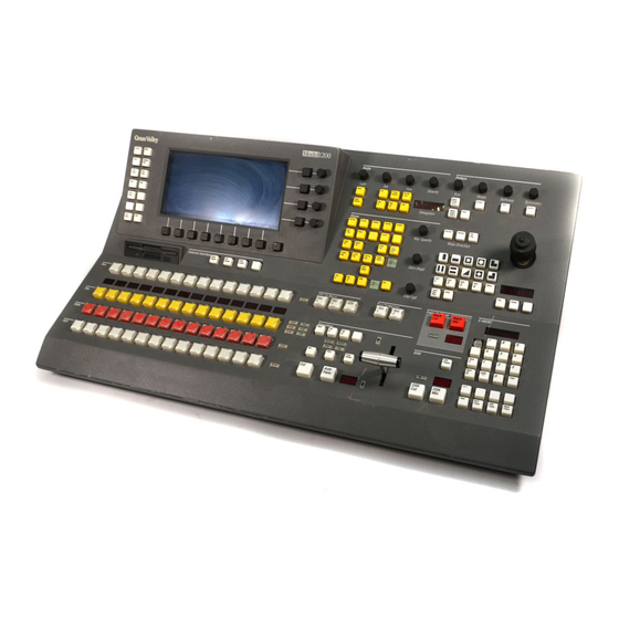
Section 1 Ñ System Overview Model 1200 Physical Description The Model 1200 Switcher (Figure 1-1) consists of two main assemblies: the Control Panel and the Signal Processor Frame. The frame contains the input/output options (back of frame), the video and key processing boards, the system control processor, and the frame power supply. -
Page 19: Model 1200 Features And Options
Model 1200 Features and Options The Model 1200 Component Digital Production Switcher carries forward the legacy of the industry-standard Model 100/110. Yet the Model 1200 is a powerful advance over its analog predecessor, both because of many new features and because of the tremendous advantage of digital video. -
Page 20: Keyers
Section 1 Ñ System Overview Keyers One effects keyer and one downstream keyer (DSK) standard. A second effects keyer is optional. Each keyer is a self-contained submodule that mounts on the Keyer Board. Keyers can be swapped for troubleshooting. Each keyer creates luminance, linear, and preset pattern keys from any Key Bus input. -
Page 21: E-Mem Effects Memory System
A keyboard is required to assign Signal and Crosspoint names and to access the menu diagnostics. Use either a keyboard acquired from Grass Valley (Marquardt Mini Board Keyboard #EA2452) or a standard PC/AT keyboard. The keyboard requires an adaptor (CA4216) which is included with the Model 1200. -
Page 22: Model 1200 Functional Overview
Section 1 Ñ System Overview Model 1200 Functional Overview The Model 1200 architecture (Figure 1-2) consists of a single mix/effects system with two keyers and a downstream keyer. Video inputs selected on the background crosspoint buses enter a pair of program and preview mixers. - Page 23 Model 1200 Functional Overview The aux buses automatically select the manipulated key and fill inputs returning from the DPM and apply them to the corresponding mixer. The mixers multiply the processed background and key signals to produce mixed effects video. The effects video enters the downstream key mixers where the DSK signal is mixed over the effects layer.
-
Page 24: Model 1200 System Specifications
Section 1 Ñ System Overview Model 1200 System Specifications Model 1200 specifications are listed in Table 1-1. The specifications for the Model 1200 are subject to change without notice. Table 1-1. Model 1200 System SpeciÞcations Parameter Value Environmental Characteristics Operating Ambient Temperature 0 - 40°... - Page 25 Model 1200 System Specifications Table 1-1. Model 1200 System SpeciÞcations - (continued) Parameter Value Control Power SpeciÞcations Power 200 Watts Maximum Voltage 90-135 VAC & 180-265 VAC (Manual) Frequency 50-60 Hz Analog External Reference Input Video Input Type Analog 525 lines, 60 Hz vertical rate or Analog 625 lines,...
- Page 26 Section 1 Ñ System Overview Table 1-1. Model 1200 System SpeciÞcations - (continued) Parameter Value Analog CAV Output Characteristics Number Of Outputs 1 PGM, 1 PVW (both optional) Luminance 1.0 Volt pp with sync Color Difference 350 mV pp bipolar DC On Output Blanking Level <...
- Page 27 Model 1200 System Specifications Table 1-1. Model 1200 System SpeciÞcations - (continued) Parameter Value Serial Digital Output Characteristics Outputs Per Module 2 (two) 75 ohm BNC Return Loss > 15 dB 5MHz to 270 MHz Output Amplitude 800 mV pp terminated DC Level On Output <...
- Page 28 Section 1 Ñ System Overview Table 1-1. Model 1200 System SpeciÞcations - (continued) Parameter Value Serial Digital Output Characteristics Maximum Number Of Inputs 16, parallel or serial digital Blanking Width 10.222 microseconds (525 line) 10.666 microseconds (625 line) Number Of Quantization Bits...
-
Page 29: Introduction
Installation Introduction This section describes the installation and setup of a Model 1200 Digital Switcher. The following main topics are discussed: UnpackingÑpage 2Ð2 Information Required Before InstallationÑpage 2Ð2 Control Panel InstallationÑpage 2Ð4 Signal Processor Frame InstallationÑpage 2Ð6 Cable RoutingÑpage 2Ð7 Cabling ConnectionsÑpage 2Ð8... -
Page 30: Unpacking
A standard PC/AT keyboard or a keyboard acquired from Grass Valley (Marquardt Mini Board Keyboard #EA2452). The keyboard requires an adaptor (CA4216) which is included with the Model 1200. Assorted Screwdrivers: Flat-blade, Phillips, and T10 TORX (optional) Nutdriver and assorted sockets Drill and 5/32Ó... -
Page 31: Summary Of Installation Specifications
CAUTION To prevent static damage to sensitive electronic components, protect the Model 1200 Digital Switcher from static discharge: Touch the Frame before you remove any modules. This helps ensure that any potential difference between your body and the frame is dissipated. If you handle the modules or make any repairs to them,... -
Page 32: Control Panel Installation
Section 2 Ñ Installation Control Panel Installation The control panel consists of a single unit which you can place on a desktop as shown in Figure 2-1 or flush mount in a console as shown in Figure 2-2. Be sure to leave room behind the panel for making cable connections and above the panel for opening the lid. -
Page 33: Figure 2-2 Dimensions For Flush-Mounting The Panel In A Console
Control Panel Installation 20.22 in. (514 mm) 6.05 in. 1.00 in. (154 mm) (25 mm) 5.31 in. 1.02 in. (135 mm) (26 mm) 15.40 in. (391 mm) 18.42 in. (468 mm) 19.58 in. (497 mm) Flush Mount Important: Install the mounting brackets on the rear of the Wood screws, 10 places, panel using four #6-32... -
Page 34: Signal Processor Frame Installation
Section 2 Ñ Installation Signal Processor Frame Installation The Signal Processor Frame (assembly 094900) mounts in a standard 19- inch wide equipment rack and requires 6 rack units of vertical space. Install the frame into the rack from the front, and secure it at the front edges with screws and nylon washers (not supplied) and at the back with the supplied rear support plate and bracket. -
Page 35: Cable Routing
INPUT 9 INPUT 10 INPUT 11 INPUT 12 ANALOG OUTPUTS INPUT 13 INPUT 14 INPUT 15 INPUT 16 GRASS VALLEY GROUP MODEL 1200 VOLTAGE: 100–240VAC ~ CURRENT: 4A FREQUENCY: 50–60HZ CAUTION – RISK OF FIRE AUX OUT 1 AUX OUT 2... -
Page 36: Cable Connections
PVW OUT PGM OUT 2 Clean Feed Video Program Video Aux Bus 1 and 2 (Program without DSK) Component Digital and Effects Send Component Digital Output Outputs Component Digital Outputs Preview Video Component Digital Output Figure 2-5. Model 1200 Frame Backplane... - Page 37 MODEM EDITOR INPUT 12 Digital Picture Manipulator PUT MODULE Serial I/O Port ANALOG OUTPUTS INPUT 16 GRASS VALLEY GROUP PUT MODULE MODEL 1200 VOLTAGE: 100–240VAC ~ CURRENT: 4A Modem FREQUENCY: 50–60HZ Serial I/O Port CAUTION – accepts a modem for...
-
Page 38: Control Panel J1 To Frame J29
Section 2 Ñ Installation Control Panel J1 to Frame J29 Connect the supplied panel-to-frame control cable (assembly 054000) from panel connector J1 (see Figure 2-6) to frame connector J29. If installing a DPM-100/700 also, donÕt mix up the control cables because equipment damage can result. -
Page 39: External Reference Input To Frame J25/J26 And Panel J3/J4
Cable Connections External Reference Input to Frame J25/J26 and Panel J3/J4 Connect a reference source of analog color black video to frame connector J25. Then connect a cable from frame connector J26 to panel connector J3 to loop the reference to the panel. Loop the reference from panel connector J4 to another destination or terminate J4 with a 75-ohm precision termination. -
Page 40: Video And Key Outputs J17Ðj24 And J33Ðj38
Section 2 Ñ Installation Video and Key Outputs J17ÐJ24 and J33ÐJ38 Connect the video and key outputs to any desired destinations. Output delay is approximately 63 µs relative to the inputs. Digital outputs conform to CCIR 601 4:2:2 component digital video standards and may be either serial or parallel, depending on which output options have been ordered. -
Page 41: Modem Connection
The Satellite Aux Panel option can connect to any port except J28. Use the control cable that comes with the option and set the port for RS-422, 200/ 1200 Aux Protocol, 9600 baud, 8 bits, 1 stop bit, no parity. See the end of this section for additional satellite panel installation details. -
Page 42: Serial Port Jumper Settings
Section 2 Ñ Installation Serial Port Jumper Settings 1. Remove the Control Processor module from the frame. 2. Locate the three sets of jumpers near the back left corner of the module. 3. Set the jumpers for the RS-232 or RS-422 communication standard as required by equipment connected to the serial ports. - Page 43 Cable Connections Parallel Component Digital Video Input/Output Control Panel J29 Female 15-pin D 8 NC 15 +14V Sense + 7 +14V Sense - 14 Transmit - 6 Panel +9V 13 Transmit + 5 Lamp +14V 12 Data Common 4 Lamp +14V 11 Data Common 3 NC 10 Receive +...
-
Page 44: Ac Power Connection And System Powerup
Figure 2-8. Model 1200 Connector Pinouts AC Power Connection and System Powerup 1. Plug the switcher frame power cord into the back of the Model 1200 frame at AC LINE IN connector J39 (Figure 2-9). Connect the other end of the cord to an AC power source between 100 and 240 volts, 50Ð60 Hz. -
Page 45: Figure 2-10 Control Panel Power Switch
If you are unable to resolve the problem using the Troubleshooting information, contact your equipment supplier for warranty service. When the Model 1200 is powered up the system software installed at the NOTE: factory will automatically load. If there are any problems with the software, please refer to Software Installation or Upgrade in the Maintenance section of this manual. -
Page 46: Restart
Section 2 Ñ Installation Restart If the system becomes confused or locks up, you can restart it as explained below. The effect you were working on will be lost, but E-MEM contents and conÞguration Þles will remain intact. 1. Press the menu button in the upper left corner of the control [MISC] panel (see Figure 2-11). -
Page 47: System Setup
System Setup System Setup The following procedures allow you to configure the 1200 system to your installation. Using the Configuration menus in the menu display, you can assign sources to the crosspoints, configure the inputs, set output levels, adjust system timing, and set other system parameters. These menu items are accessed through the Configuration menu (Figure 2-12) on the Menu Display subpanel. -
Page 48: Configuration Menu
Section 2 Ñ Installation Configuration Menu The Configuration menu (Figure 2-13) and its s sub-menus allow you to set up the switcher to meet your requirements. To begin the setup process, press the button next to the menu display to bring up [CONFIG] the Configuration menu, which includes the following sub-menus and functions:... -
Page 49: System Parameters Menu
System Setup System Parameters Menu Use the System Parameters menu (Figure 2-14) as explained below to set the aspect ratio (ratio of television picture width to height), to set the field dominance for use with an editor, and to set the system clock. 1. -
Page 50: Define Inputs Menu
Section 2 Ñ Installation Define Inputs Menu From the Configuration menu select to display the Define Inputs [INPUTS>] menu (Figure 2-15). This menu is typically configured during switcher installation. However, you may want to change configurations for different types of production sessions. The Inputs menu allows you to do the following: Give each physical input a descriptive name which is carried forward into several other menu levels. -
Page 51: Chroma Key Sources Menu
System Setup 6. Assign the Effects Return Flag to a video and a key source by highlighting them and pressing soft button. This [EFX RTN FLAG] identifies that video/key input pair as the Effects Send signals returning from a Digital Picture Manipulator. When Effects Send is on, the switcher will automatically select these inputs. -
Page 52: Crosspoint Display Legends Menu
Section 2 Ñ Installation Crosspoint Display Legends Menu Display the Crosspoint Display Legend menu by selecting [XPT DISP from the Define Inputs menu (Figure 2-17). This menu allows LEGENDS>] you to assign a unique name (up to 4 characters) to each physical input. The name will display above the crosspoint column to which that physical input is mapped. -
Page 53: Crosspoint Map Menu
System Setup Crosspoint Map Menu The Crosspoint Map menu (Figure 2-18) is selected by pressing the [CONFIG] button and then the button. [XPT MAP>] 1. Set the soft button to the [[XPT MAP SELECT] NORMAL ALTERNATE crosspoint map. Using this function, you can define two completely different crosspoint maps and switch between them as desired. -
Page 54: Outputs Menu
From the Configuration menu, select to display the Outputs [OUTPUTS>] menu (Figure 2-19). This menu allows you to set up signal formats for Model 1200 outputs. 1. Use the soft knob to highlight the name of the output to be (OUTPUT) configured. -
Page 55: Timing Menu
System Setup Timing Menu Input timing is automatic; however, you can adjust the overall timing manually in the Timing menu (Figure 2-20) to ensure that auto-timing captures all inputs. When you make this adjustment, you are advancing or delaying the Reference input, which causes a corresponding movement of the auto-timing capture window for the primary inputs and also causes a corresponding movement of the switcher outputs. -
Page 56: Ports Menu
GRASS VALLEY PRODUCTS 1200 Communication is RS-422, 38.4Kbaud, 8 bits, 1 stop bit, odd parity. You may also use switcher protocol if your editor does not have a 1200 interface, but functionality will be reduced. ÑUse protocol (RS-422, 9600 AUX SATELLITE PANEL PORT 1200 AUX baud, 8 bits, 1 stop bit, no parity). -
Page 57: Figure 2-21 Ports Configuration Menu
PORT CONFIGURATION MENU BAUD STOP PORT RATE BITS PARITY BITS PORT PROTOCOL ADDR 9600 NONE TERMINAL 38.4K PANEL 1200 PNL PROTOCOL 2400 MODEM MODEM NONE = MODEM 38.4K EDITOR 1200 38.4K ADDRESS = 00 EVEN BAUD RATE NONE = 2400... -
Page 58: Gpi Menus
Section 2 Ñ Installation GPI Menus The GPI Inputs menu (Figure 2-22) is displayed when you press the top menu button followed by the soft button. From this [CONFIG] [GPI>] menu, you can view the GPI Inputs or access the GPI Outputs menu (Figure 2-23). -
Page 59: Figure 2-22 Gpi Inputs Menu
System Setup GPI INPUTS SELECT GPI INPUT INPUT # STATE EVENT OPEN EFFECT CUT OPEN EFFECT AUTO TRAN CLOSED DISK CUT SELECT CLOSED E-MEM 1 LEARN EVENT OPEN E-MEM RECALL = 10 OPEN AUX 1 TALLY BACK OPEN EFFECT KEY 1 CUT OPEN AUX 2 CROSSPOINT 3 GPI Inputs are ENABLED... -
Page 60: Tally Menu
Section 2 Ñ Installation Tally Menu The Tally menu (Figure 2-24) allows you to test and observe the switcherÕs tally outputs to determine whether your connections to external devices are working. This menu also includes an (Aux Bus Tally AUX TLY BACK Back) selection. -
Page 61: Installing Panel Pushbutton Lens Chips
System Setup Installing Panel Pushbutton Lens Chips After assigning inputs to crosspoints, you can install the supplied lens chips (button labels) in the crosspoint pushbuttons. To remove a pushbutton lens, grasp the pushbutton lens firmly with your fingers and pull the lens off of the button. Then install the lens chip on top of the pushbutton and push the lens back into place. -
Page 62: Option Installation
Section 2 Ñ Installation Option Installation Options ordered with the switcher are installed and fully tested at the factory and require no installation. However, if you order options at a later time, you can use the instructions that follow to help you install them. After installing the option(s), refer to the previous pages for setup instructions. - Page 63 Option Installation 064914 SPG Submodule 064911 Control Processor Module 064906 Chroma Keyer Submodule 064905 Crosspoint Module 064909 Borderline 064909 Borderline 064909 Borderline 064908 Key 1 Processor 064908 Key 2 Processor 064908 DSK Processor 064907 Keyer Module 064912 DAC Option 064913 Depth Option 064910 Program Mixer Module 064912 DAC Option 064913 Depth Option...
-
Page 64: Analog Output Option Installation
Section 2 Ñ Installation Analog Output Option Installation Installation of the Analog Output (DAC: Digital-to-Analog) option consists of the following steps, which are explained in detail on the following pages: Mounting the option mezzanine boards on the Program or Preview Mixer module. - Page 65 Analog Output Option Installation DAC SUPPORT SPACE FOR OPTION PROGRAM PREVIEW MIXER MODULE Figure 2-28. Installing the Analog Output Option (DAC) Modules 2-37...
-
Page 66: Setting Analog Output Option Jumpers
Section 2 Ñ Installation Setting Analog Output Option Jumpers The Analog Output Option leaves the factory set to produce the following analog output signal parameters: 0.700V peak signal level No Setup RP125 narrow blanking To change any of these parameters, follow the steps given below: Blanking Width and Video Setup 1. -
Page 67: Video Format
Analog Output Option Installation Video Format 1. Remove the 064815 Analog Output mezzanine board (the small mezzanine on top) from the 064912 Analog Output Support mezzanine board. This entails removing four (4) screws around the perimeter of the Analog Output board and gently pulling the board straight up. When you have removed the 064815 Analog Output mezzanine board, turn it over to view the component side. - Page 68 Section 2 Ñ Installation Table 2-1. Analog Output Option Jumper Settings J4 (Y) J8 (R-Y) J10 (B-Y) J5, J6, J9, J11 Format Analog Output Analog Analog Analog Analog Output Selection Support Output Output Output Format Setup Format Format Format EBU/SMPTE No Setup RGB .714 v No Setup...
-
Page 69: Adjusting Analog Output Gain
Analog Output Option Installation Adjusting Analog Output Gain The format selection jumpers provide a convenient way to select signal levels that are accurate enough for most monitoring purposes. However, if your application demands precise signal levels, you may need to adjust signal gain using the gain adjustments on the Analog Output mezzanine board: 1. - Page 70 Section 2 Ñ Installation COLOR DIFFERENCE FORMATS –– –– –– –– -300 -300 –– -286 -300 –– -300 R–Y: -350 -467 -467 -467 -350 -324 -324 B–Y: -350 -467 -467 -467 -350 -324 -324 –– –– –– –– –– Y with ––...
- Page 71 Analog Output Option Installation RGB FORMATS -286 -300 -286 -286 -300 -286 -286 -300 -286 NOTE: All voltage levels are in millivolts. Figure 2-30. RGB Signal Level Standards 2-43...
-
Page 72: Satellite Auxiliary Bus Control Panel Option
Section 2 Ñ Installation Satellite Auxiliary Bus Control Panel Option The Satellite Auxiliary Bus Panel provides remote control of the switcherÕs auxiliary buses. See Figure 2-31 and the text below for installation. 1. Install the Satellite Panel in the rack or console. See the figure for dimensions. - Page 73 Analog Output Option Installation 7.50" (19.0CM) 17.00" (43.2CM) 19.00" (48.3CM) 1.72" (4.4CM) DC connector Power Supply Transformer 120 or 230 Vac selectable, Removable Rack Ears 50–60 Hz, 10 Watts May be repositioned or removed for flush mounting in a console AC Connector J2-Serial Control J1-DC Power input...
- Page 74 Section 2 Ñ Installation 2-46...
-
Page 75: Introduction
Functional Description Introduction This section describes the internal architecture of the Model 1200 Switcher. The following main topics are discussed: System OverviewÑpage 3Ð2 Frame ModulesÑpage 3Ð10 Control PanelÑpage 3Ð38... -
Page 76: System Overview
Section 3 Ñ Functional Description System Overview As you read the overview, please refer to Figure 3-1. CHROMATTE™ KEYER CARRIER AND 4:2:2/4:4:4 CHROMA EFFECTS SEND KEY OPTION MODULE AUX 1 SERIAL AUX 2 INPUT OPTION SERIAL INPUT OPTION BORDERLINE MIX/EFFECTS KEY EDGE KEYER 1 GENERATOR... - Page 77 System Overview EFFECTS SEND VIDEO •••••••••••• SEND & •••••••••• OR AUX 1 OUT AUX BUS OUTPUT SEND KEY •••••••••••• OPTION •••••••••• OR AUX 2 OUT ANALOG DIGITAL-TO-ANALOG PROGRAM CONVERTER VIDEO OPTION (YUV, RGB, OR Y R-Y B-Y) PROGRAM VIDEO MIXER PARALLEL ••••••••••••...
-
Page 78: Service Philosophy
Model 1200, troubleshooting and field repair of the individual printed circuit modules is not practical. This section is designed to help you determine which module in the Model 1200 may be at fault in the event of a problem. You should then contact your equipment supplier or Grass Valley Products Customer Support for module replacement or repair. -
Page 79: Video Signals
Input ModulesÑEach input goes through a Serial or Parallel Input Module where the signal is converted to the TTL level parallel video that is required by the Model 1200. The clock is also stripped off for timing the video. Crosspoint ModuleÑAfter going through the Input Module the video is sent to the Crosspoint Module. -
Page 80: Options
Section 3 Ñ Functional Description Key Processor SubmoduleÑThe standard system has a Key Processor Submodule for Key 1 and the DSK. The Key Processor Submodule uses the key source and the key fill video to create a key cutter and video fill that are put over the background video in the mixer. -
Page 81: Control Signals
The CPU writes control values only to modules that are installed. Timing Signals In the Model 1200, all timing signals are generated in the Sync Pulse Generator Submodule. This submodule plugs into the Control Processor Module. The timing signals are sent to the Control Processor Module where they go through fanout and distribution to the various video modules. -
Page 82: Scaling
The 1200 configuration menus ask you to identify video inputs as shaped or unshaped because the switcher handles those two types of fill video signals differently. For keying with shaped fill video, the keyer multiplies only the background video with the key signal to cut a hole in the background, and then adds the already-shaped fill video into the hole. -
Page 83: Internal Accuracy
The Model 1200 can handle 16 X 9 video. The digital video 16 X 9 signal is handled the same as 4 X 3 video. For 16 X 9, the Model 1200 must have the setup reflect that input. The system can not handle 4 X 3 and 16 X 9 video at the same time. -
Page 84: Frame Modules
Frame, I/O Modules -5.2 Volts 12 Amps I/O Modules +9 Volts 1 Amp not used with Model 1200 +15 Volts 2 Amp not used with Model 1200 +12 Volts 0.5 Amps The input voltage can be 100 to 240 Volts, 50 to 60 cycles. The power supply is autoranging and power factor corrected. -
Page 85: Control Processor Module
Frame Modules Control Processor Module The Control Processor Module (Figure 3-2) has overall control of the system. All of the control and interface functions originate here. There are two microprocessors and associated circuitry on the module. The 68302 I/O processor handles the following: The system boot The operating system The external interface... -
Page 86: System Boot
After the diagnostics run, the 68302 looks for an operating system in the flash EEPROM. If a system is found, the system is transferred to the RAM of both processors; then the Model 1200 boots from RAM. The field LEDs are on during the vertical interval while that processor is reading and writing. -
Page 87: Sync Pulse Submodule
The Sync Pulse Generator Submodule (Figure 3-3) does the following: Determines the television standard of the reference input (525, 625) Automatically switches the Model 1200 to the correct standard Has the system clock which is locked to the input reference... -
Page 88: Sync Pulse Generator Circuit
Section 3 Ñ Functional Description Sync Pulse Generator Circuit The reference black signal is first buffered and low pass filtered to remove the subcarrier. From the resulting signal the clamp pulse generator creates burst flag and sync. Signals from the clamp generator are then used as control signals on a sample and hold. -
Page 89: Input Modules
Both circuits in one module are identical. The circuits convert from the ECL level signal on the cable to the TTL levels that are used in the Model 1200. The video or key goes from the Input Module into the Crosspoint Module. -
Page 90: Crosspoint Module
Section 3 Ñ Functional Description Crosspoint Module Autotiming and Chrominance/Luminance Split On the Crosspoint Module (Figure 3-6) the video first enters a circuit which auto-times all of the input signals to the reference black signal then splits the signal into luminance and chrominance signals. The key signals are handled the same way except that they are split into key and depth. -
Page 91: Crosspoint Matrix
Frame Modules Crosspoint Matrix The Crosspoint Matrix (Figure 3-6) consists of 16 inputs by 16 outputs by 10 bits repeated twice, once for luminance and once for chrominance. Not all of the available outputs are used. The crosspoint matrix is designed so that any of the inputs can be connected to any of the outputs without limits. -
Page 92: Chroma Keyer Submodule
The Fringe Control causes the Hue Correlation circuit to respond to areas in the input scene that have little or no chroma. The two Hue Correlation circuits on the 1200 chroma keyer are called background and foreground. The Background Hue Correlation circuit is used for background color suppression and for generation of the chroma key signal. - Page 93 AutoCKey circuit to capture luminance and chrominance data at the location identified by the cursor. The captured data is read by the 1200 CPU for each field and used to calculate the reference hue, luma suppression level, VGC clip and gain, and shadow clip level.
- Page 94 Section 3 Ñ Functional Description Hposition Vposition Crosshair Generator To Shdw Proc BKGD CK_Y White Coring Color Color Suppression Suppression CK_C CBlack Interpolation (Outputs to Size, Crosspoint Softness, Limit Module) Position C(U)Bkgd Autockey C(V)Bkgd Circuit Subtract/ Codd 4:4:4 Interface Limit YBkgd &...
-
Page 95: Keyer Module
Aux 1 and Aux 2 output buses, which can be connected to a DPM for manipulation of the key. The signal returning to the Model 1200 from the DPM re-enters on one of the primary inputs and is routed to the effects send crosspoints on the Aux 1 and Aux 2 input buses. -
Page 96: Wipe Pattern Generator
Section 3 Ñ Functional Description Wipe Pattern Generator The Wipe Pattern Generator (Figure 3-9) produces a single wipe pattern output which is used two places: A 16-bit signal is sent to the Mixer Module for wipe transitions A 10-bit signal which has been Clip and Gain adjusted goes to each of the Key Processor Submodules to create the Preset Pattern Key The Wipe Waveform Generator creates digital horizontal and vertical ramps. -
Page 97: Key Processor Submodule
Frame Modules Key Processor Submodule The Key Processor Submodule (Figure 3-10) generates the following signals: Preset pattern key with or without border Luminance key with or without mask Linear key with or without mask The functions of some Key Processor circuits change according to the type of key being generated. -
Page 98: Preset Pattern Keys
Section 3 Ñ Functional Description Preset Pattern Keys Pattern New is the outer edge of the new video and Pattern Old is the inside edge of the old video. The space between (if any) is the border. The positions of these signals are determined by the Keyer Module. The Pattern Old signal passes through the Tri Clip and Gain circuit and gets selected by the multiplier. -
Page 99: Borderline Submodule
Frame Modules Borderline Submodule A Borderline Submodule option (Figure 3-11) can be mounted on each of the Key Processor Submodules. The purpose of the Borderline is to expand the key horizontally and/or vertically to put a border or shadow around it. The Horizontal Key Stretch circuit will, under the control of the CPU, delay the key one pixel and then do a Non Additive Mix (NAM) between the original signal and the delayed signal. -
Page 100: Program Mixer Module
Section 3 Ñ Functional Description Program Mixer Module The Program Mixer Module (Figure 3-12): Generates the Clean Feed Out Generates the Program Out Processes the depth information Has the Transition Generator Bkgnd A Key Out A PROC KEY AND DEPTH OUTPUT Key Out B PROCESSING... -
Page 101: Clean Feed Out
Frame Modules Clean Feed Out A and B Backgrounds enter into the Program Mixer Module from the Crosspoint Module (see Figure 3-13). They each go through a Proc Amp and then enter a Mixer circuit. The Mixer circuits use the Background A and Background B Control signals to determine how much of each signal will feed the Background Combiner circuit. -
Page 102: Dsk
Section 3 Ñ Functional Description The DSK Video Mix Multiplier (Figure 3-14) takes the DSK video and the data from the CPU to mix the DSK fill signal on and off. The DSK Key Mix Multiplier does the same for the DSK Key. The Video Mixer takes the DSK Fill, the Clean Feed Video, and the DSK Key to create the Program Video signal. -
Page 103: Key And Depth Output Processing
Frame Modules Key and Depth Output Processing The Clean Key and the DSK Key (Figure 3-15) are converted from control level signals to video level signals in the mixers. The selectors will allow either of the key and depth inputs to be put on either or both of the key outputs. -
Page 104: Transition Generators
Section 3 Ñ Functional Description Transition Generators The Transition Generator (Figure 3-16) creates the control signals for each of the mixers. The T1 and T2 (Transition Old and Transition New) are created by the Clip and Gain from the Wipe Pattern. Pattern Old is the outer edge of the old video. - Page 105 Frame Modules Transition Transition Key 1 Mix Key 2 Mix Bkgd A Mix Bkgd B Mix COEF COEF COEF COEF Transition Center CLIP Pri Dpt Pri Dpt GAIN Wipe Pattern CLKRX To Depth Submodule Key 1 VARIABLE DELAY CLOCK Cof 1-2 Mix Key 2 COEF VARIABLE...
-
Page 106: Depth Submodule
Section 3 Ñ Functional Description Depth Submodule The Depth Demultiplexer (Figure 3-17) takes the ten-bit wide two-byte depth signal and converts it to a 20-bit wide single byte. Since the signal is still being clocked at half rate, the Depth Interpolation will add a byte between each of the existing bytes by averaging between the two existing bytes. - Page 107 Frame Modules CLIP Priority Depth PRIORITY DEPTH GAIN GENERATOR SHAPING Key 1 CLIP GAIN DEPTH Key 1 INTERPOLATION DEPTH DEPTH Depth DEMUX SHAPER OFFSET ADDER Clean Feed DEPTH Key Depth Transition OFFSET DELAY REMUX Center GENERATOR DEPTH Key 2 INTERPOLATION DEPTH DEPTH Depth...
-
Page 108: Analog Output Option (Dac) Submodule
Section 3 Ñ Functional Description Analog Output Option (DAC) Submodule The Analog Output (DAC: Digital-to-Analog Converter) option consists of the 064912 DAC Support board and the 064815 DAC board. The Support board prepares the video signal for conversion and also provides decoding and latching of the clock and control signals used by the DAC. - Page 109 Frame Modules LUM_DACLN Half- Y_DAC Delay LUM_DADTY Delay Band Filter CHR_DACLN Blanking B-Y_DAC Half- Half- Mixer Delay Band Band CHR_DADTY Filter Filter R-Y_DAC Half- Half- Band Band Filter Filter Blanking Sync Timing H, V, FID Clamp Sequencer Setup Data, Processor Address Strobe, S/W Control Interface...
-
Page 110: 064815 Dac Board
Section 3 Ñ Functional Description 064815 DAC Board The DAC board (Figure 3-19) receives an 8:8:8 digital video signal from the DAC Support board and converts the signal to component analog video. The converted signal drives the 75 ohm analog outputs at the back of the switcher frame. -
Page 111: Preview Mixer Module
Frame Modules Preview Mixer Module The Preview Mixer Module and all the submodules on the module are identical to the Program Mixer Module. Output Modules The Output Modules (Figure 3-20) have two functions. They combine the video and the video clock, and they convert the video from the TTL internal signal to the ECL digital video on the output. -
Page 112: Control Panel
The power supply is easy to replace and is not designed to be user serviceable. Control Panel Overview The Model 1200 Control Panel (Figure 3-21) contains five circuit boards which hold the pushbutton switches, controls, lamps, the switch and control encoding logic, and the lamp decoding logic. When pushbuttons are pressed and knobs are turned on the panel, the resulting voltage changes are encoded by the switch and control encoding logic. -
Page 113: Control Panel Modules
Control Panel Control Panel Modules The Model 1200 Control Panel contains seven module assemblies: the Control Panel I/O module (064919), the Control Panel MPU module (064926), the Crosspoints module (064920), the E-MEM module (064921), the Display Surround module (064922), the Matte/Key/Wipe module... -
Page 114: Panel Scanning
Section 3 Ñ Functional Description Panel Scanning The Control Processor and the Control Panel MPU buses are linked by a serial data connection. Refer to Figure 3-22. 1. At the beginning of each TV field, the I/O board sends a video sync signal to the control panel MPU generating an interrupt. -
Page 115: Introduction
Maintenance Introduction This section explains the maintenance of a Model 1200 Digital Switcher. The following main topics are discussed: OverviewÑpage 4Ð2 Servicing PrecautionsÑpage 4Ð2 Servicing ProceduresÑpage 4Ð4 Routine MaintenanceÑpage 4Ð5 Circuit Module ReplacementÑpage 4Ð8 Lever Arm AdjustmentÑpage 4Ð11 Software Installation or UpgradeÑpage 4Ð13 System Power Down ProcedureÑpage 4Ð16... -
Page 116: Overview
Failure to observe this precaution may result in overheating of components. Powering Down Most maintenance operations on the Model 1200 switching system recommend that you to turn equipment power off before making repairs to or removing circuit modules and assemblies. Refer to System Power Down Procedure text on page 4-16 of this manual. -
Page 117: Removing Circuit Modules
OFF and then back ON again. The power-up sequence will re-synchronize the microprocessors. Repairing Circuit Modules Model 1200 circuit modules are not designed to be repaired in the field. Failed modules should be replaced. Multi-layer circuit board and surface-mount manufacturing techniques have been used in many of the circuit modules. -
Page 118: Servicing Procedures
Power Supply Configurations The standard power supply configuration of the Model 1200 is a single supply chassis for the Signal Processor Frame and single supply chassis for the Control Panel. The power supply chassis are separately connected to AC source power and each chassis supplies independent voltage/current buses. -
Page 119: Routine Maintenance
LEDs on the front of the frame modules are lit. The LEDs to check are listed under the Status Indicator heading later in this section. Turn off power and remove the power cord from the Model 1200 before touching or removing any frame modules to access fuses. -
Page 120: Pushbutton Lamp Replacement
Section 4 Ñ Maintenance Pushbutton Lamp Replacement During normal operation, the buttons on the Control Panel light up to indicate their activated state. If a lamp in any button fails to light when it should, it should be replaced. The lamp bulb (#7382) is removed by carefully pulling the button cap up out of the panel, then pulling the bulb out of the Switch. -
Page 121: Using The Module Extender
Routine Maintenance Using the Module Extender The 064917 Extender enables you to extend modules outside the frame so that you can probe circuits and test points while they are powered up. Figure 4-2 shows how to use the Extender. UNFOLD EXTENDER AND LOCK KNOBS IN PLACE 3 SLIDE MODULE INTO... -
Page 122: Circuit Module Replacement
Section 4 Ñ Maintenance Circuit Module Replacement Repairing Circuit Modules Model 1200 circuit modules are not designed to be repaired in the field. Faulty modules should be replaced. Multi-layer and surface-mount printed circuit manufacturing techniques have been used in the manufacture of many of these circuit modules. -
Page 123: Control Panel Modules
Circuit Module Replacement Control Panel Modules The locations of Control Panel module boards are illustrated in Figure 4-3. Display Crosspoints Peripheral E-MEM Matte/Key/Wipe Surround Module Enable Module Module Module (064920) Module (064921) (064923) (064922) (064924) Disk Drive Cable Converter 3-slot ISA I/O Module Control Panel MPU On (1)/Off (0) - Page 124 2. Unplug the AC line cord from the AC source or the control panel. The AC line cord is located at the rear of the Control Panel. 3. On the Model 1200 Control Panel remove any control knobs, that would interfere with removal of the assembly.
-
Page 125: Lever Arm Adjustment
Lever Arm Adjustment Lever Arm Adjustment To adjust the Lever Arm: 1. Open the control panel and locate the Matte/Key/Wipe module (064923) inside the control panel (see Figure 4-4). Center the R604 (Offset) and the R605 (Gain) pots. 2. On the I/O board (064919), turn the rotary switch to 1. R604 (Offset) R605... - Page 126 Section 4 Ñ Maintenance 3. The diagnostic menu will immediately appear on the screen. Enter the letter C using the keyboard to access the Leverarm and Joystick test menu (see Figure 4-5). Testing leverarms and joysticks . . . Press any key to stop the test . . . JoyLever Raw—Lever—2 sec—...
-
Page 127: Software Installation Or Upgrade
Saving E-MEM Data to Diskette Before you install new software in the Model 1200, save any E-MEM files created during your operation. Refer to the Operation ManualÕs Disk menu text for the save-to-disk procedure. -
Page 128: Loading Software From Diskette
Section 4 Ñ Maintenance Loading Software From Diskette Before beginning this procedure, save all current E-MEM effects and NOTE: Switcher setups to disk as this procedure erases all current E-MEMs and setups in memory. 1. Open the control panel and locate the I/O board (064919). Refer to Figure 4-6. - Page 129 Software Installation or Upgrade 5. Return power to the control panel using the ON/OFF switch, and the system begins loading the floppy driveÕs software disk. 6. Observe the Menu display. A series of messages appear before you have to do anything else. When the download is complete (after about 4 minutes), the screen indicates the control panel download is done and instructs you to install the Frame software diskette.
-
Page 130: System Power Down Procedure
Section 4 Ñ Maintenance System Power Down Procedure The following procedure is to be used when removing power from the system. 1. Press main menu button. MISC 2. Select [SHUT DOWN] System warns that shut down halts the frame and requires you to turn the power OFF and then ON, or press the frameÕs reset button (see Figure 4-7). -
Page 131: System Restart After Power-Serge
3. The system asks whether to . Select CONFIRM CONFIRM CANCEL 4. The Model 1200 frame begins clearing the frame Dual Ported RAM, and for approximately 10 seconds, the screen displays CLEAR DPRAM is in progress... The screen then displays Wait 5 seconds for DPRAM has been cleared. - Page 132 . Select CONFIRM. CONFIRM CANCEL 7. The 1200 system begins resetting the Model 1200 frame back to factory default settings, and for approximately 18 seconds, the screen displays FACTORY RESET is in progress... The screen then displays Wait 5 seconds for Factory reset completed.
-
Page 133: Introduction
Diagnostics and Troubleshooting Introduction This section of the manual provides information to assist you in isolating faults that may occur in the Control Panel or Signal Processing Frame. For safety, service should only be performed by qualified personnel. The following main topics are discussed: OverviewÑpage 5Ð2 General TroubleshootingÑpage 5Ð3 Detailed TroubleshootingÑpage 5Ð6... -
Page 134: Overview
CAUTION Do not operate the Model 1200 system with the Signal Processing Frame doors or covers open or removed for an extended period, as overheating may occur. In order to avoid loss of data, be sure to read the Service Precautions and... -
Page 135: General Troubleshooting
See the Operation manual for complete operation instructions. Check Setup Use the Configuration menus to check the setup of the Model 1200. If you want to reset the system to factory default setup, use the [FACTORY RESET] soft button in the System Parameters menu. -
Page 136: Perform Visual Checks
Signal Processor frame are plugged in. Verify that all of the cables are connected properly. Check the function of all of the other equipment hooked up to the Model 1200 for proper function. Check Status Indicators Verify that all of the status indicators are giving the proper indications as explained under the headings that follow. -
Page 137: Program Loading Indicators
LEDs do not light, there is probably a hardware problem in the sending/receiving device, the Model 1200 serial drivers, serial port configuration jumpers, or the interconnecting cable. If there is a UART setup error, the LEDs should still operate properly. -
Page 138: Detailed Troubleshooting
3. Replace Power Supply Processor and baud rate, parity etc. in the config/ports menu. 2. Send data to Model 1. Check fuse on that 1200 and check for module correct serial port LED Power to flash: Module? 2. Verify that module a. - Page 139 Detailed Troubleshooting Start 1. Check AC fuses inside: AC Input Connector Frame Power Supply 2. Check for power on power cord Power to 3. Replace Power Supply System? 1. Check fuse on that module 2. Verify that module Power to is plugged in Module? 1.
- Page 140 Submodule or Keyer Module Bad or Missing ALL KEYS Keys? 1. Check Keyer Module Figure 5-3. Trouble TreeÑMiscellaneous After trying the steps outlined in the Trouble Trees if you are still having NOTE: problems contact Grass Valley for further instructions.
-
Page 141: Exchanging Modules
Exchanging Modules Exchanging Modules If you suspect that a particular frame module is faulty, you may be able to test it by exchanging it with another frame module. The following frame modules are interchangeable: The Program Mixer Module and the Preview Mixer Module The Program Depth Submodule and the Preview Depth Submodule Any of the Keyer Submodules on the Keyer Carrier Module Any of the Borderline Submodules on the Keyer Submodules... -
Page 142: Menu Diagnostics
Section 5 Ñ Diagnostics and Troubleshooting Menu Diagnostics The software that runs in the Model 1200 control panel can be placed in a diagnostic mode. The diagnostic menu contains a list of tests that can be run to determine items such as whether lamps are burned out or knobs or buttons are not functioning properly. - Page 143 G - discrete LED test H - comm port loopback test Return rotary switch to position 0 to exit diagnostics and return to DOS. At the DOS prompt, use '1200' to restart Enter letter to select test: Exit Figure 5-5. Diagnostic Menu 4.
-
Page 144: Diagnostic Tests
H - comm port loopback test Return rotary switch to position 0 to exit diagnostics and return to DOS. At the DOS prompt, use '1200' to restart Enter letter to select test: A Testing displays . . . Use any knob to adjust speed . . . -
Page 145: Knob Test
Menu Diagnostics Knob Test Selecting from the Diagnostic menu will cause the menu [B - knob test] screen to appear as in Figure 5-7. Testing knobs . . . Press any key to stop the test . . . Knob Filt Filt Raw—Delta—2 sec—... -
Page 146: Lever Arm And Joystick Test
Section 5 Ñ Diagnostics and Troubleshooting Lever Arm and Joystick Test Selecting from the Diagnostic menu will cause [C - leverarm and joystick test] the menu screen to appear as in Figure 5-8. Testing leverarms and joysticks . . . Press any key to stop the test . -
Page 147: Button/Lamp Dim Test
H - comm port loopback test Return rotary switch to position 0 to exit diagnostics and return to DOS. At the DOS prompt, use '1200' to restart Enter letter to select test: D Lamps will light (DIM if lamp can be dimmed) when button is pres Press any key to stop the test . -
Page 148: Button/Lamp Bright Test
H - comm port loopback test Return rotary switch to position 0 to exit diagnostics and return to DOS. At the DOS prompt, use '1200' to restart Enter letter to select test: E Lamps will light (BRIGHT if lamp can be brightened) when button is pres Press any key to stop the test . -
Page 149: Walking Lamp Test
Menu Diagnostics Walking Lamp Test Selecting from the Diagnostic menu will cause the [F - walking lamp test] screen to appear as in Figure 5-11. Walking lamp test . . . Use any knob to adjust speed . . . Press any key to stop the test . -
Page 150: Discrete Led Test
Section 5 Ñ Diagnostics and Troubleshooting Discrete LED Test Selecting from the Diagnostic menu will cause the [G - discrete LED test] screen to appear as in Figure 5-12. Discrete LED test . . . Use any knob to adjust flash rate . . . Press any key to stop the test . -
Page 151: Comm Port Loopback Test
G - discrete LED test H - comm port loopback test Return rotary switch to position 0 to exit diagnostics and return to DOS. At the DOS prompt, use '1200' to restart Enter letter to select test: H This test isn't implemented yet. -
Page 152: Exiting Diagnostics
Section 5 Ñ Diagnostics and Troubleshooting Exiting Diagnostics To return to normal operation: 1. Open the control panel and locate the I/O board (064919). 2. On the I/O board, turn the rotary switch to 0 (see Figure 5-15). On (1)/Off (0) Switch Normal Diagnostic... -
Page 153: Index
Index Numerics 1200 Configuration Menu Tree 2-19 Cable 16 X 9 3-9 Connections 2-8 4:4:4 Chroma Key Sources Menu 2-23 Pinouts 2-16 Routing 2-7 Chroma Key Functional Description 3-24 Sources 2-23 AC Power Chroma Keyer, Functional Description 3-18 Connection 2-16... - Page 154 Module Block Diagram 3-36 Modules, Functional Description 3-10 Support Module, Block Diagram 3-35 Using the Extender Module 4-7 Define Inputs 2-22 Functional Overview, Model 1200 1-6 Depth Output Processing 3-29 Fuse Replacement 4-5 Depth Submodule Function Description 3-32 Overview 3-6...
- Page 155 Index Cable Pinouts 2-16 Connection, Overview 2-13 Indicators 5-4 Module Replacement, Control Panel 4-9 Input Connector J1ÐJ16 2-11 Define 2-22 Module, Functional Definition 3-15 Option Module, Overview 3-6 Functional Overview 3-6 Options 1-3 Installation 2-34 Specifications 1-9 Output Installation Menu 2-26 Control Panel 2-4 Module Frame 2-6...
- Page 156 Index Functional Description 3-7 Startup System 3-12 Overview 1-3 Sync Pulse Generator Submodule 3-7, 3-13 Program System Key Output Connector 2-12 Boot 3-12 Mixer Parameters 2-21 Module, Block Diagram 3-26 Startup 3-12 Overview 3-6 PGM Output Connector 2-12 Pushbutton Lamp Replacement 4-6 Tally J28 Connector 2-14 Menu 2-32...
Need help?
Do you have a question about the 1200 and is the answer not in the manual?
Questions and answers