GRASS VALLEY KAYENNE XL PACKAGE 7.0.3 - INSTALLATION AND SERVICE MANUAL REV 8-2010 Installation And Service Manual
Kayak hd digital production switcher
Hide thumbs
Also See for KAYENNE XL PACKAGE 7.0.3 - INSTALLATION AND SERVICE MANUAL REV 8-2010:
- User manual (624 pages)
Table of Contents
Advertisement
Quick Links
Download this manual
See also:
User Manual
Advertisement
Table of Contents

Related Manuals for GRASS VALLEY KAYENNE XL PACKAGE 7.0.3 - INSTALLATION AND SERVICE MANUAL REV 8-2010


Summary of Contents for GRASS VALLEY KAYENNE XL PACKAGE 7.0.3 - INSTALLATION AND SERVICE MANUAL REV 8-2010
- Page 1 Kayenne XL Package KAYAK HD DIGITAL PRODUCTION SWITCHER Installation and Service Manual Software Version 7.0.3 071870003 AUGUST 2010...
- Page 2 Affiliate with the N.V. KEMA in The Netherlands CERTIFICATE Certificate Number: 510040.001 The Quality System of: Thomson Inc, and it’s wordwide Grass Valley division affiliates DBA GRASS VALLEY Headquarters 15655 SW Greystone Ct. 10 Presidential Way 400 Providence Mine Rd...
- Page 3 Kayenne XL Package KAYAK HD DIGITAL PRODUCTION SWITCHER Installation and Service Manual Software Version 7.0.3 071870003 AUGUST 2010...
- Page 4 Germany, Austria, Eastern Europe: +49 6150 104 444 UK, Ireland, Israel: +44 118 923 0499 Copyright © Thomson, Inc. All rights reserved. This product may be covered by one or more U.S. and foreign patents. Grass Valley Web Site www.grassvalley.com web site offers the following: —...
-
Page 5: Table Of Contents
Contents Safety Summary Safety Terms and Symbols..........Terms in This Manual . - Page 6 — Contents Touch Screen Menu Panel Installation ........Menu Panel Dimensions .
- Page 7 Grass Valley Web Site ..........Grass Valley Customer Support FAQ Database ......
- Page 8 — Contents PLX Driver ............USB Serial Driver .
-
Page 9: Safety Summary
Safety Summary Read and follow the important safety information below, noting especially those instructions related to risk of fire, electric shock or injury to persons. Additional specific warnings not listed here may be found throughout the manual. WARNING Any instructions in this manual that require opening the equipment cover or enclosure are for use by qualified service personnel only. -
Page 10: Symbols On The Product
Safety Summary Symbols on the Product The following symbols may appear on the product: Indicates that dangerous high voltage is present within the equipment enclosure that may be of sufficient magnitude to constitute a risk of electric shock. Indicates that user, operator or service technician should refer to product manual(s) for important operating, maintenance, or service instructions. -
Page 11: Cautions
Safety Summary — Use only the power cord supplied or specified for Use proper power cord this product. — Connect the grounding conductor of the power cord to Ground product earth ground. — Do not operate this Operate only with covers and enclosure panels in place product when covers or enclosure panels are removed. - Page 12 Safety Summary — If you suspect product damage Do not operate with suspected equipment failure or equipment failure, have the equipment inspected by qualified service personnel. — If mains switch is not provided, the power cord(s) Ensure mains disconnect of this equipment provide the means of disconnection. The socket outlet must be installed near the equipment and must be easily accessible.
- Page 13 Safety Summary Sicherheit – Überblick Lesen und befolgen Sie die wichtigen Sicherheitsinformationen dieses Abschnitts. Beachten Sie insbesondere die Anweisungen bezüglich Brand-, Stromschlag- und Verletzungsgefahren. Weitere spezifische, hier nicht aufgeführte Warnungen finden Sie im gesamten Handbuch. WARNUNG Alle Anweisungen in diesem Handbuch, die das Abnehmen der Geräteabdeckung oder des Gerätegehäuses erfordern, dürfen nur von qualifiziertem Servicepersonal ausgeführt werden.
- Page 14 Safety Summary Symbole am Produkt Die folgenden Symbole können sich am Produkt befinden: Weist auf eine gefährliche Hochspannung im Gerätegehäuse hin, die stark genug sein kann, um eine Stromschlaggefahr darzustellen. Weist darauf hin, dass der Benutzer, Bediener oder Servicet- echniker wichtige Bedienungs-, Wartungs- oder Servicean- weisungen in den Produkthandbüchern lesen sollte.
- Page 15 Safety Summary — Berühren Sie bei eingeschalteter Strom- Keine offen liegenden Leiter berühren zufuhr keine offen liegenden Leitungen, Komponenten oder Schaltungen. — Verwenden Sie nur das mitgelieferte Netzk- Richtiges Netzkabel verwenden abel oder ein Netzkabel, das den Spezifikationen für dieses Produkt entspricht.
- Page 16 Safety Summary — Um eine Überhitzung des Geräts zu vermeiden, Gerät ausreichend belüften müssen die Ausrüstungskomponenten entsprechend den Installationsan- weisungen belüftet werden. Legen Sie kein Papier unter das Gerät. Es könnte die Belüftung behindern. Platzieren Sie das Gerät auf einer ebenen Oberfläche.
- Page 17 Safety Summary Consignes de sécurité Il est recommandé de lire, de bien comprendre et surtout de respecter les informations relatives à la sécurité qui sont exposées ci-après, notamment les consignes destinées à prévenir les risques d’incendie, les décharges élec- triques et les blessures aux personnes. Les avertissements complémen- taires, qui ne sont pas nécessairement repris ci-dessous, mais présents dans toutes les sections du manuel, sont également à...
- Page 18 Safety Summary Symboles apposés sur le produit Les symboles suivants peut être apposés sur le produit: Signale la présence d’une tension élevée et dangereuse dans le boîtier de l’équipement ; cette tension peut être suffisante pour constituer un risque de décharge électrique. Signale que l’utilisateur, l’opérateur ou le technicien de main- tenance doit faire référence au(x) manuel(s) pour prendre con- naissance des instructions d’utilisation, de maintenance ou...
- Page 19 Safety Summary — Évitez tout contact avec les connex- Évitez tout contact avec les circuits exposés ions, les composants ou les circuits exposés s’ils sont sous tension. — Utilisez exclusivement le cordon Utilisez le cordon d’alimentation approprié d’alimentation fourni avec ce produit ou spécifié pour ce produit. —...
- Page 20 Safety Summary — Pour éviter toute surchauffe du produit, Assurez une ventilation adéquate assurez une ventilation de l’équipement conformément aux instructions d’installation. Ne déposez aucun document sous l’appareil — ils peuvent gêner la ventilation. Placez l’appareil sur une surface plane. - Les composants sensibles à...
-
Page 21: Section 1 - Introduction
Section Introduction General Using Open Sources Software This product contains free software code released under the GNU General Public License (GPL) Version 2 (available at http://www.gnu.org/licenses/gpl.txt) and free software released under the GNU Lesser General Public License (LGPL) Version 2.1 (available at http://www.gnu.org/licenses/lgpl.txt) and free software released under the GNU Lesser General Public License (LGPL) Version 3 (available at http://www.gnu.org/licenses/lgpl.txt). -
Page 22: Overview
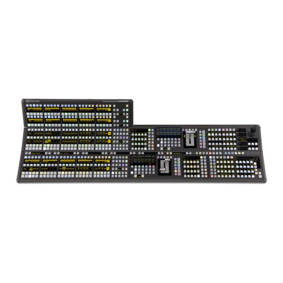
Section 1 — Introduction Overview The Grass Valley Kayak HD family of multi-format digital production switchers provides powerful, ground-breaking features designed to meet the widest range of requirements for live studio, mobile, and post-produc- tion applications. Available in configurations ranging from 1-ME to 4.5-MEs, Kayenne XL Packages combine features available in the Grass... - Page 23 Kayenne XL Package design, permitting customized operator control layouts. Representative Kayenne XL control surfaces are shown in the following illustrations. Control panel options are available that do not include the menu panel or the PCU for adding a panel using one PCU. Up to 8 stripes are supported on one PCU.
-
Page 24: Flat Or Curved Control Panel Orientation
Section 1 — Introduction Flat or Curved Control Panel Orientation The main Kayenne XL Control Panel supports different physical orienta- tions. Besides a conventional flat surface, a special support design permits a curved working surface, where the MEs progressively tilt for improved ergonomics (Figure Figure 6. -
Page 25: Touch Screen Menu Panel And Pc Menu Control
Kayenne XL Package • KAYN-PNL-SRC-35, 25, 15 - Source Module, available in 35, 25, and 15 button widths, used for ME source selection. • KAYN-PNL-BAR-35, 25, 15 - Panel Bar, available in three sizes to match various control panel widths, used for device control and macros. •... -
Page 26: Satellite Panels
Section 1 — Introduction Satellite Panels Two satellite panel options are available for mounting control panel modules outside of the main control panel. One option supports one module and another options supports two modules. Each consumes one PCU port. Redundant Power Supplies Optional built-in redundant power supplies are available for the Kayak HD Frame 4-RU and 8-RU Frames. -
Page 27: Supported Control Protocols
Jupiter™ and Encore™ router control systems) • Control Systems (Grass Valley Andromeda™ and third-party systems) • Grass Valley Under Monitor Displays (Serial tally for UMD. Requires Grass Valley Andromeda™ system or third-part tally box such as Tally Display Corp. -
Page 28: Specifications
Section 1 — Introduction Specifications Kayenne XL Package Table 1. Kayenne XL Mechanical Specifications Component Depth (Flat) Width Height (Flat) Weight Rack Units Control Panels 84.3 mm 1533.7 mm 651.3 mm 4.5ME-35, w/o Aux Panel (3.32 in.) (60.38 in.) (25.6 in.) 84.3 mm 1533.7 mm 3.5ME-35, w/o Aux Panel... - Page 29 Specifications Table 4. PCU Interconnects Control Panel - PCU Connections Cable and connectors Custom 7 Pin D style Number of connections 1 for each Control Panel Stripe, Local Aux Panel, and Satellite Panel Max. Interconnect Cable Length 15m / 50ft (7.5m / 25ft cable length also available) Touch Screen Menu Panel - PCU Connection Cable and connectors Custom 17 Pin D style...
- Page 30 Section 1 — Introduction Table 6. Serial Digital Video Inputs HD Video Formats SMPTE 292M-1998 Interface SD Video Formats SMPTE 259M-1997 Nominal Amplitude 800mV peak-to-peak terminated Autophasing range Channel Coding conforms to SMPTE 259M, SMPTE 292M Ancillary Data Blanked or passed (user selectable) Embedded audio Blanked or passed (user selectable) Blanked...
- Page 31 Specifications Table 9. Kayenne XL Video Standards HD Mode SD Mode 1080i 29.97/30 SMPTE 274M Table 1-4, 5 525i 59.94 SMPTE 259M 1080i 25 SMPTE 274M Table 1-6 625i 50 SMPTE 259M 1080p 24/23.976 SMPTE 274M Table 1-10, 11 1080sF 24/23.976 SMPTE 211 Table 1-15, 16 Kayenne XL Package —...
- Page 32 Section 1 — Introduction Kayenne XL Package — Installation and Service Manual...
-
Page 33: Section 2 - Control Surfaces
Section Control Surfaces Introduction A Kayenne XL Control Surface has a modular Control Panel, a Local Aux Panel, a Menu Panel, and a Panel Control Unit (PCU) frame. Additional Touch Screen Menu Panels and Satellite Panels are available as options. A Control Panel consists of system operation modules, which mount into trays, which are in turn held in place by a control panel support structure. -
Page 34: Control Panel Cooling
Section 2 — Control Surfaces Two Control Panel Assembly orientations are possible, flat and curved. The curved panel provides improved operator ergonomics, but raises the Control Panel height which could restrict the visibility of the lower portion of a monitor wall. An assembled Control Panel can be operated from a tabletop (the support structure includes rubber feet), or it can be installed into a cutout. -
Page 35: Control Panel Cut Out
Control Panel Assembly Control Panel Cut Out Figure 9. 4-ME Control Panel Cutout Dimensions, Curved Installation 4-ME 35 Panel Cutout 1503.5 +/-1 mm 59.2 +/-.04 in. 625 +/-1 mm 4-ME Panel Curved Install Cutout 24.6 +/-.04 in. 1311.5 +/-1 mm 51.6 +/-.04 in. -
Page 36: Control Panel Mounting Points
Section 2 — Control Surfaces Control Panel Mounting Points For fastening the control panel in place, please use the six brackets as shown in Figure 10 on page 36. Depending on the material of the availabe desk the control panel can be fastened with sheet metal screws 3.9 mm or crosshead screws 4 mm Figure 10. - Page 37 Control Panel Assembly Figure 11. 4-ME Support Structure, Curved Installation 862 0 3200 85 57 2820 D E T A IL C 850 0 44 20 8557 2810 D E T A IL B 8557 2800 8500 4420 86 20 3170 862 0 3200 85 57 28 30 855 7 2720...
-
Page 38: 4-Me 35 Control Panel, Flat With Attached Aux
Section 2 — Control Surfaces 4-ME 35 Control Panel, Flat with Attached Aux Figure 12. 4-ME 35 Control Panel Dimensions, Flat Installation 1533.7 mm 124.0 mm 60.4 in. 813.5 mm 4.9 in. 32.0 in. 771.5 mm 30.4 in. 10.4 mm 1501.5 mm 14.3 mm 0.4 in. -
Page 39: 4-Me 25 Control Panels
Control Panel Assembly Figure 14. 4-ME Support Structure, Flat Installation 8557 2830 85 57 27 10 85 57 27 10 85 57 2820 855 7 28 30 862 0 32 00 8557 2820 8557 2820 85 00 44 20 8500 442 0 862 0 31 80 8557 2890 86 20 3200... -
Page 40: 3-Me 35 Control Panel, Curved With Attached Aux
Section 2 — Control Surfaces 3-ME 35 Control Panel, Curved with Attached Aux Figure 16. 3-ME 35 Control Panel Dimensions, Curved Installation 1533.7 mm 60.4 in. 813.5 mm 208.0 mm 32.0 in. 8.2 in. 10.3 mm 14.8 mm 0.4 in. 0.6 in. -
Page 41: 3-Me 25 Control Panels
Control Panel Assembly Figure 18. 3-ME Support Structure, Curved Installation 855 7 2820 8620 3200 D E T A IL C D E T A IL B 850 0 442 0 855 7 28 10 8557 2800 86 20 31 80 86 20 32 00 85 00 76 20 850 0 442 0... -
Page 42: 2-Me 35 Control Panel, Curved With Attached Aux
Section 2 — Control Surfaces 2-ME 35 Control Panel, Curved with Attached Aux Figure 20. 2-ME 35 Control Panel Dimensions, Curved Installation 1533.7 mm 60.4 in. 813.5 mm 158.0 mm 32.0 in. 6.2 in. 10.3 mm 0.4 in. 474.1 mm 1501.5 mm 74.0 mm 18.7in. -
Page 43: 2-Me 25 Control Panels
Control Panel Assembly Figure 22. 2-ME Support Structure, Curved Installation 855 7 2820 862 0 3200 8620 3180 8557 2830 850 0 442 0 8500 7620 850 0 76 20 862 0 3200 85 57 2860 86 20 31 70 855 7 27 10 850 0 442 0 85 57 28 00... -
Page 44: 2-Me 35 Control Panel, Flat Without Aux
Section 2 — Control Surfaces 2-ME 35 Control Panel, Flat without Aux Figure 24. 2-ME 35 Control Panel Dimensions, Flat Installation 10.3 mm 1533.7 mm 0.4 in. 60.4 in. 325.4 mm 1501.5 mm 74.0 mm 12.8 in. 59.1 in. 2.9 in. Figure 25. -
Page 45: 1-Me 15 Control Panel Without Local Aux
Control Panel Assembly 1-ME 15 Control Panel without Local Aux Figure 27. 2-ME 35 Control Panel Dimensions, Flat Installation 10.3 mm 758.3 mm 0.4 in. 29.9 in. 325.4 mm 1501.5 mm 74.0 mm 12.8 in. 28.6 in. 2.9 in. Figure 28. 2-ME Control Panel Cutout Dimensions, Flat Installation 728 +/-1 mm 28.7 +/-.04 in. -
Page 46: Separately Mounted Local Aux Panel (35 & 25 Models)
Section 2 — Control Surfaces Separately Mounted Local Aux Panel (35 & 25 Models) Figure 30. Local Aux Panel Separate Installation Dimensions Local Aux 25 Width Local Aux 35 Width 10.3 mm 621.7 mm 813.7 mm 0.4 in. 24.5 in. 32.0 in. -
Page 47: Control Panel Module Installation
Control Panel Assembly Control Panel Module Installation Tray Internal Cabling Each Kayenne XL Control Panel tray is equipped with a distribution board located at the bottom of the tray. Each Control Panel module connects to a module port on this distribution board inside the tray, using a CAT 6 (shielded) style cable. - Page 48 Section 2 — Control Surfaces Each module can be taken separately from the mixer. • Insert a card and push down behind the module at the notch. Underneath the notches are metal springs, which will be unlocked with the card. After unlocking all springs one after another, the module releases easily upwards.
- Page 49 Control Panel Assembly Insert Modules: • Connect the Cat 6 style cable at the lower surface of the module before inserting the module. The cable should be looped in order to avoid damage. At the front edge of the module there are alignment pins, which must insert in respective holes in the module tray.
- Page 50 Section 2 — Control Surfaces Removal of the System Bar: The System Bars are part of the PP control panel stripe only. Each System Bar is fixed to the tray with one screw. For removal, a 2.5 mm hexagonal driver (Allen wrench) is required. •...
-
Page 51: Changing The Display-Protecting Glasses
Control Panel Assembly Insert the System Bars: • For installing the Extended System Bar first connect the flat cable. • Place the System bar into the appropriate position. • Tighten it with the screw without pushing down. The module pulls itself into the plug while tightening the screw. - Page 52 Section 2 — Control Surfaces CAUTION Do not connect or disconnect the multi-pin cables linking a Kayenne XL Control Panel tray and PCU while the PCU is powered up. Damage to the equipment can result. Section 4-System Cabling for more information about Kayenne XL panel cable connections.
-
Page 53: Touch Screen Menu Panel Installation
Touch Screen Menu Panel Installation Touch Screen Menu Panel Installation Menu Panel Dimensions Figure 32. Menu Panel Dimensions Front View Side View, Right 417.8 mm 16.45 in. 64.1 mm 2.52 in. 270.0 mm 10.63 in. 76.2 mm 12.7 mm 3.00 in. 5.0 in. -
Page 54: Menu Panel Connectors
Section 2 — Control Surfaces Menu Panel Connectors The Kayenne XL Touch Screen Menu Panel’s processor is located in the PCU. The Menu panel connects to the PCU with a special multi-pin cable that carries both power and communications signals. CAUTION Do not connect or disconnect the multi-pin cables linking a Kayenne XL Touch Screen Menu Panel tray and PCU while the PCU is powered up. -
Page 55: Additional Kayenne Xl Menu Panels
Touch Screen Menu Panel Installation Additional Kayenne XL Menu Panels An additional touch screen Kayenne XL Menu Panel is available as an option. An optional Menu Panel processor board is inserted into the PCU for this added panel, and another multi-pin power and signal cable is used for that panel. -
Page 56: Menu Panel Articulated Arm Installation
Section 2 — Control Surfaces Menu Panel Articulated Arm Installation The Kayenne XL Touch Screen Menu Panel has VESA 75 threads on the back that can be used to mount the Menu Panel to the supplied articulated arm, or any VESA compliant mounting system. Figure 34. -
Page 57: Satellite Panels
Satellite Panels Satellite Panels Two satellite panel options are available for mounting control panel modules outside of the main control panel. One option supports one module and another options supports two modules. Each satellite panel option consumes one PCU port. For more details refer sectionsKayenne XL Cabling on page 83 Satellite... -
Page 58: One Module Version
Section 2 — Control Surfaces One Module Version Overview Figure 35. Satellite Panel - Overview One Module Version Kayenne XL Package — Installation and Service Manual... -
Page 59: Dimensions
Satellite Panels Dimensions Figure 36. Satellite Panel - Dimensions One Module Version 17.9 149.9 ±1 PA NE L C UT OUT Kayenne XL Package — Installation and Service Manual... -
Page 60: Two Module Version
Section 2 — Control Surfaces Two Module Version Overview Figure 37. Satellite Panel - Overview Two Module Version Kayenne XL Package — Installation and Service Manual... -
Page 61: Cutout Dimensions
Satellite Panels Cutout Dimensions Figure 38. Satellite Panel - Dimensions Two Module Version 315.4 17.9 298.6 ±1 PA NE L CU TOUT Kayenne XL Package — Installation and Service Manual... - Page 62 Section 2 — Control Surfaces Kayenne XL Package — Installation and Service Manual...
-
Page 63: Section 3 - Kayak Hd Frames
Section Kayak HD Frames General Rack Mounting Instructions Weight Distribution Make sure that you mount the unit in the rack so that it is evenly balanced to prevent damage to the frame and to avoid creating a hazardous condi- tion. Cooling Requirements The maximum ambient temperature for this unit is 40-degrees C (104- degrees F). -
Page 64: Kayak Hd 8-Ru Video Processor Frame Installation
Section 3 — Kayak HD Frames Kayak HD 8-RU Video Processor Frame Installation 8-RU Frame Dimensions Figure 39. Kayak HD 8-RU Frame Dimensions 1 of 2 483 mm 19.0 in. 465 mm 18.31 in. 166 mm 6.5 in. 355 mm 13.97 in. - Page 65 Kayak HD 8-RU Video Processor Frame Installation Figure 40. Kayak HD 8-RU Frame Dimensions 2 of 2 Cable Support Wires Top view 541 mm 21.29 in. 523 mm 20.58 in. 37 mm 1.43 in. 442 mm 17.4 in. Kayenne XL Package — Installation and Service Manual...
-
Page 66: 8-Ru Frame Rack Mounting
Section 3 — Kayak HD Frames 8-RU Frame Rack Mounting Figure 41. Kayak HD 8-RU Frame Dimensions Exhaust Intake Rear Rack Support CAUTION Mounting using only the front rack ears is sufficient for fixed installations. Additional support, like the rear rack support or slide rails, is required for mobile applications. -
Page 67: 8-Ru Frame Connectors
Kayak HD 8-RU Video Processor Frame Installation Make sure to provide adequate ventilation for the Kayak HD Frame. When installing the frame in the rack, take care that no ventilation holes are blocked. This can prevent cooling air from reaching the frame and cause it to overheat. -
Page 68: Internal Redundant Power Supply Option
Section 3 — Kayak HD Frames Figure 43. Kayak HD 8RU Frame, Backplane View Video In Video Out 1 M/E: 1-24 1 M/E: 1-12 GPI In/Out 1-8 GPI In/Out 9-16 2 M/E: 1-48 2 M/E: 1-24 Tallly 1-24 Tallly 25-48 (Internal Switch 3 M/E: 1-72 3 M/E: 1-36... -
Page 69: Kayak Hd 4-Ru Video Processor Frame Installation
Kayak HD 4-RU Video Processor Frame Installation Kayak HD 4-RU Video Processor Frame Installation 4-RU Frame Dimensions Figure 44. Kayak HD 4-RU Frame Dimensions 482 mm 19.0 in. 465 mm 18.31 in. Front view Figure 45. Kayak HD 4-RU Frame Dimensions 442 mm 17.4 in. -
Page 70: 4-Ru Frame Rack Mounting
Section 3 — Kayak HD Frames 4-RU Frame Rack Mounting Figure 46. Kayak HD 4-RU Frame Rack Installation and Cooling Airflowg Exhaust Rear Rack Support Intake Mounting using only the front rack ears is sufficient for fixed installations. Additional support, like the rear rack support or slide rails, is required for mobile applications. -
Page 71: 4-Ru Frame Connectors
Kayak HD 4-RU Video Processor Frame Installation 4-RU Frame Connectors Figure 47. Kayak HD 4RU Frame, Front View with Door Removed Top M/E Slot Controller Flash Power Reset 2 USB Bottom M/E Slot M/E 0 (PP) (and 0.5 M/E) Memory Switch Button RS-232 (unused) -
Page 72: Panel Control Unit (Pcu)
Section 3 — Kayak HD Frames Panel Control Unit (PCU) PCU Dimensions Figure 49. Panel Control Unit, Front View Dimensions 132.6 mm 5.22 in. 483 mm 19.0 in. Kayenne XL Package — Installation and Service Manual... - Page 73 Panel Control Unit (PCU) Figure 50. Panel Control Unit, Top View Dimensions 442.0 mm 17.4 in. 18.0 mm 0.71 in. 530.9 mm 20.90 in. 39.6 mm 1.56 in. Kayenne XL Package — Installation and Service Manual...
-
Page 74: Pcu Frame Rack Mounting
Section 3 — Kayak HD Frames PCU Frame Rack Mounting Figure 51. Panel Control Unit Rack Installation and Cooling Airflow Exhaust Rear Rack Support Intake Kayenne XL Package — Installation and Service Manual... -
Page 75: Pcu Connectors
Panel Control Unit (PCU) PCU Connectors Figure 52. Panel Control Unit, Front View Panel Processor Menu Processor Power Panel Serial Port Serial Port Menu Switch Reset Keyboard Com 1 Com 1 Keyboard Reset Status Status Display & Compact Display & USB (2) USB (2) Boot Switch... -
Page 76: Internal Redundant Power Supply Option
Section 3 — Kayak HD Frames The PCU has an internal Ethernet switch, used for Menu Panel processor communications. Six Ethernet ports are available on the back. Two ports used internally for the Menu Panels. An additional Ethernet port is used for Control Panel processor communications. -
Page 77: Section 4 - System Cabling
Section System Cabling Overview The Kayenne XL system uses Ethernet, serial, and USB connections. Custom multi-pin cabling is also used to connect the Kayenne XL Panel Control Unit (PCU) to Kayenne XL control surface and Menu Panel compo- nents. The Kayak HD Video Processor Frame and PCU each have built-in Ethernet switches. -
Page 78: Network Cabling
Section 4 — System Cabling Kayenne XL system power is provided by power supplies built into the Kayak HD Video Processor Frame and Kayenne XL PCU. Power is routed to control surface components and Menu Panels from the PCU through the custom multi-pin cabling. - Page 79 Network Cabling The PCU Ethernet switch to Frame Ethernet switch cable connection is used for Menu Panel communications. The second cable connects the Panel PCU directly to the Frame’s Ethernet switch. Using two cables provides additional Ethernet communications throughput (to support Image Store file operations) and also offers redundancy.
-
Page 80: Multiple Kayenne Xl Workplaces
Section 4 — System Cabling Multiple Kayenne XL Workplaces A Kayenne XL / Kayak HD system can be divided into two or more work- places. The system resources (MEs, eDPMs, external devices, etc.) can be assigned to each workplace, creating two or more switchers with one Kayenne XL / Kayak HD system. - Page 81 Network Cabling Using a second PCU, Kayenne XL Panels can be located anywhere on the network, permitting system control from different rooms, floors, or even different buildings (Figure 57). Figure 57. Two Suites Using Two PCUs Kayak HD Video Processor Kayenne XL PCU 1 Frame Kayenne XL Site 1...
-
Page 82: Customer Supplied Ethernet Routers And Switches
Section 4 — System Cabling Customer Supplied Ethernet Routers and Switches Existing facility Ethernet switches can be used in conjunction with a Kayenne XL/Kayak HD system. If connecting to a network area outside that used by the Kayenne XL/Kayak HD system, use of an appropriately configured Ethernet Router is strongly advised. -
Page 83: Kayenne Xl Cabling
Kayenne XL Cabling Kayenne XL Cabling Connectors on the outside bottom of the Control Panel tray connect to numbered ports on the PCU, using special multi-pin cables that carry both power and communications signals. Special cables are also used to connect the Menu Panels to the PCU. - Page 84 Section 4 — System Cabling Figure 58. Example 4-ME Control Panel Port Port Port Port Port Port Port Port Kayenne XL Package — Installation and Service Manual...
- Page 85 Kayenne XL Cabling Figure 59. Assignment of the Panel Stripe Connectors 1-ME 15 Control Panel PCU Port 2 PCU Port 1 2-ME 25 Control Panel PCU Port 3 PCU Port 1 PCU Port 2 3-ME 35 Control Panel PCU Port 4 Optional PCU Port 1 Module...
-
Page 86: Satellite Panel Mapping
Section 4 — System Cabling Satellite Panel Mapping If you connect a Satellite Panel the right mapping to an existing M/M stripe has to be observed. Rules Please note the following simple rules. • An M/E stripe is determined by the existence of a crossbar module (Rool: No crossbar module, no M/E stripe). -
Page 87: Video Cabling For All Kayenne Xl Switchers
Video Cabling for all Kayenne XL Switchers Video Cabling for all Kayenne XL Switchers All Kayenne XL system video inputs and outputs are configurable. For cabling configuration flexibility, each external primary input can be mapped to any Kayenne XL panel source select button, as can each internal video system source. -
Page 88: Video Timing And Delay
Section 4 — System Cabling Video Timing and Delay The total delay of a video input to the switcher output can vary according to the relationship of the input to the switcher reference. The switcher will automatically autotime inputs that fall within an autotiming window. Inputs must be within this range to be properly timed at the output. - Page 89 Video Timing and Delay Table 15. Kayak HD System Timing, 4.5 ME System HD Mode SD Mode System Timing 720p/ 720p/ 1080i & sf/ 1080i & sf/ 1080sf/ 525i/ 625i/ 59.94/60 29.97/30 23.97/24 29.97 Nominal Switcher Delay 21.96 µs 19.79 µs 26.46 µs 23.50 µs 27.20 µs...
-
Page 90: Timing Analyzer
Section 4 — System Cabling Timing Analyzer The Timing menu on switcher systems (accessed via Install – E-Box – Tining) has a Timing Analyzer pane, which can help when timing the system. Figure 61. Install - E-Box - Timing Pane This analyzer reports the timing position of a selected source relative to the Kayak HD internal sync generator. -
Page 91: Time Zones And The Autotiming Window
Video Timing and Delay Time Zones and the Autotiming Window Each ME has a fixed amount of delay from its input to output. To allow reentries to remain in time, ME timings are staggered such that the up stream ME outputs are in time (or earlier) than down stream ME inputs. A 4-1/2 ME production switcher has six time zones to accommodate reentry through all the MEs to any output (Figure... -
Page 92: Kayenne Xl Input Timing Range
Section 4 — System Cabling Kayak HD/Kayenne XL Input Timing Range Table 16. Kayak HD input timing range guide values (Software Verstion V703 with AUX-Transition) 1 M/E 1.5 M/E 2 M/E 2.5 M/E 3 M/E 3.5 M/E 4 M/E 4.5 M/E Video Pixel/Line input... -
Page 93: Pin Assignments
Menu Processor. These ports are used for diag- nostics. If you need to use these ports to diagnose problems with the Kayenne XL switcher, please contact your Grass Valley Customer Service Representative. Kayenne XL Package — Installation and Service Manual... - Page 94 Section 4 — System Cabling Panel Stripe Connector (8x Rear Panel) Table 19. Socket Signal Ground 1 48V POS D-Sub Female Ground 1 Pin 2 Pin 1 48V POS Ground 1 Data OUT Coaxial A2 Coaxial A1 DATA IN Pin 3 The panel Stripe Connector is used for connecting the Control Panel.
- Page 95 Pin Assignments VGA (Front Side PC Boards) Socket Signal Red Video IN Green Video IN Blue Video IN Ground Ground Ground Ground Ground Horizontal Sync IN Vertical Sync IN Menu Panel (2x Rear Panel) Socket Signal Ground 1 Ground 1 D-Sub Female Ground 1 Ground 1...
-
Page 96: Gpi / Tally Connections
Section 4 — System Cabling GPI / Tally Connections The Kayenne XL GPI / Tally system has universal relays that interface source tally and GPI Output information to an external system through the Tally Port connectors. The channels can be assigned in the Setup menu. Tallies are a source attribute and relays can be assigned to a source when source definitions are defined in the Setup menu during initial system con- figuration. -
Page 97: Gpi Inputs
Pin Assignments GPI Inputs The purpose of the GPI In pins is to provide a stimulus from the customer's equipment to the switcher. A simple connection to the two connectors (or four in the case of the 8-RU frame) activates the corresponding input. This kind of control is suitable for a connection to a relay contact or to an open-collector output. -
Page 98: Gpi Input Structure
Section 4 — System Cabling GPI Input Structure Figure 63. GPI Input Connections (Typical 2 of 8 connections) + 3.3 V Opto Isolator 50-pin Connector (1 of 8) Pin Numbers 150 ohm Open GPI 1 Collector + 3.3 V Opto Isolator (5 of 8) 150 ohm GPI 5... -
Page 99: Gpi / Tally Outputs
Pin Assignments Refer to the Install Menus section of the Kayenne XL User Manual for details on setting the input signal activating edge. Configuration Menu section of the Kayenne XL User Manual for Refer to the details on setting the function of a GPI input. GPI / Tally Outputs There is a great deal of flexibility in the hardware and programmability of the GPI / Tally outputs. - Page 100 Section 4 — System Cabling Figure 64. GPO Tally Connections 50-pin Connector Pin Numbers 1A of 32 2A of 32 Logic 3A of 32 4A of 32 Common A 5B of 32 6B of 32 Common B 12V Lamp 27G of 32 28G of 32 Common G 12V Lamp...
- Page 101 Pin Assignments Although the diagram above implies mechanical relays, the actual outputs are implemented with solid state relays. Interface specifications are: • Maximum current for any one output: 1 amp AC/DC • Maximum current for any one common: 2 amp AC/DC. •...
- Page 102 Section 4 — System Cabling 4 RU and 8RU Frame Tally (GPI In 1-8, GPI Out 1-32) Socket Ribbon Cable 50-Pin D-Sub Signal GPIInCom GPIInCom D-50 Female GPIIn1 Pin 18 GPIIn2 GPIIn3 Pin 1 GPIIn4 Pin 34 GPIIn5 GPIIn6 GPIIn7 GPIIn8 GPIOutComA GPIOut1A...
- Page 103 Pin Assignments 4 RU and 8RU Frame Tally (GPI In 9-16, GPI Out 33-64) Socket Ribbon Cable 50-Pin D-Sub Signal GPIInCom GPIInCom D-50 Female GPIIn9 Pin 18 GPIIn10 GPIIn11 Pin 1 GPIIn12 Pin 34 GPIIn13 GPIIn14 GPIIn15 GPIIn16 GPIOutComJ GPIOut33J GPIOut34J Pin 33 GPIOut35J...
- Page 104 Section 4 — System Cabling 8RU Frame Tally (GPI In 17-24, GPI Out 65-96) Socket Ribbon Cable 50-Pin D-Sub Signal GPIInCom GPIInCom D-50 Female GPIIn17 Pin 18 GPIIn18 GPIIn19 Pin 1 GPIIn20 Pin 34 GPIIn21 GPIIn22 GPIIn23 GPIIn24 GPIOutComS GPIOut65S GPIOut6S Pin 33 GPIOut67S...
- Page 105 Pin Assignments 8RU Frame Tally (GPI In 25-32, GPI Out 97-128) Socket Ribbon Cable 50-Pin D-Sub Signal GPIInCom GPIInCom D-50 Female GPIIn25 Pin 18 GPIIn26 GPIIn27 Pin 1 GPIIn28 Pin 34 GPIIn29 GPIIn30 GPIIn31 GPIIn32 GPIOutComAA GPIOut97AA GPIOut98AA Pin 33 GPIOut99AA GPIOut100AA GPIOutComAB...
- Page 106 Section 4 — System Cabling Kayenne XL Package — Installation and Service Manual...
-
Page 107: Section 5 - Maintenance
Safety Summary describes all of the pertinent safety issues and recommend precautions. Grass Valley Web Site The URL for the Grass Valley web site can be found on page 4. Visit the website for documentation, software updates, online support (including FAQs), spare parts information, and a link to the File Transfer Protocol (FTP) site. -
Page 108: Reset Procedures
Section 5 — Maintenance Reset Procedures Video Processor Frame A Video Processor Frame reset button is located near the center of the front edge of the Controller Board, accessed by opening the front door of the Frame (Figure 65). The 8-RU and 4-RU Frames use the same type of Con- troller Board. -
Page 109: Panel Control Unit (Pcu)
Reset Procedures Panel Control Unit (PCU) The PCU has up to three reset buttons, one for the Control Panel Processor, one for the standard Menu Panel, and one for the optional second Menu Panel. These controls are accessible by opening the front door of the PCU Frame (Figure 66). -
Page 110: Setting Up Ip Addresses
Section 5 — Maintenance Setting Up IP Addresses The default factory setting for the IP address is • 192.168.0.70 for the video processor frame • 192.168.0.71 for the RAMRecorder • 192.168.0.176 for Panel Processor PC • 192.168.0.177 for Menu Processor PC Setting IP Address at Panel and Mainframe An IP address is a 32-bit number that uniquely identifies each device sending or receiving information in packets across the network. - Page 111 Setting Up IP Addresses Figure 68. Select Network devices 700.02 Figure 69. Software Installation Wizard • Click Next. The Device Control menu displays every Kayenne XL or Kayak device connected to the Switcher Network. Kayenne XL Package — Installation and Service Manual...
- Page 112 Section 5 — Maintenance Figure 70. Select a displayed device • Select the device whose IP address you want to configure from the device list by touching the name. • Press the Config Device button at the bottom of the Device menu. The Configure Device menu appears.
- Page 113 Setting Up IP Addresses Figure 72. Enter new IP Address • Confirm Do you really want to change the IP address with Yes. A reboot of the system is required. Figure 73. Confirm Kayenne XL Package — Installation and Service Manual...
-
Page 114: Setting Ip Address At Menu Panel Pc
Section 5 — Maintenance Setting IP Address at Menu Panel PC • Open the Windows Start menu and select Settings / Control Panel / Network Connections and choose Local Area Connection. • Click on Properties. This opens the Local Area Connection Properties window. - Page 115 Setting IP Address at Menu Panel PC Figure 75. IP Address • Click OK to close each window. Kayenne XL Package — Installation and Service Manual...
-
Page 116: Software Update
Section 5 — Maintenance Software Update Note Before performing a software update be sure that your application data are Save Application Data. saved. For details refer your User Manual, section Installing the Sidepanel Software • Insert the Kayenne XL Package Software CD into your computer's CD- ROM drive. - Page 117 Software Update Figure 77. Kayenne Sidepanel Installation • The Sidepanel Software Installation Welcome screen displays. Click Next. Figure 78. Confirm • Choose the type of installation you wish to perform: • Demo: Demo version, no connection to a panel or a frame. •...
- Page 118 Section 5 — Maintenance Figure 79. Installation type • Select the network which is used for the switcher network and click Next: Figure 80. Select component • Click to select or deselect the check box for Desktop Picture, Full Screen Mode, Autostart Sidepanel on boot and Autostart TFTP Server on boot.
- Page 119 Software Update Figure 81. Select options • Click to select the check box for Yes, I want to restart my computer now and click Finish. Figure 82. Confirm restart Kayenne XL Package — Installation and Service Manual...
- Page 120 Section 5 — Maintenance To complete the computer connection to the panel and frame after the com- puter has rebooted. • Launch the Sidepanel software application. • Click to select the box for E-Box at the top of the screen. A blue line dis- plays in the bottom of the box to indicate that it has been selected.
-
Page 121: Installing Panel And Mainframe Software
Software Update Installing Panel and Mainframe Software • From the CD Installer Welcome screen click on the Install new software button (third from the top on the left as shown in Figure below): Figure 83. Software Installation • The Install new software selection screen is displayed. Click on Network Devices button on the right to install software over the network. - Page 122 Section 5 — Maintenance Figure 84. Network Devices • In the Device Selection screen every Kayenne XL Package and Kayak devices connected to your computer's network are displayed here in the window. Click on a name in the list to select a device for installation. •...
- Page 123 Software Update Figure 86. Software Update • Select Start Install to start the software installation on the selected device. Figure 87. Start Installation • Confirm with Yes. The installation progress will be shown at the top of the screen. • Confirm the reboot with Yes to complete the software installation. Kayenne XL Package —...
- Page 124 Section 5 — Maintenance Figure 88. Confirm Figure 89. Progress Bar Software Update Kayenne XL Package — Installation and Service Manual...
- Page 125 Software Update Figure 90. Reset Device Kayenne XL Package — Installation and Service Manual...
-
Page 126: Install A Kayennexl Stand Alone Gui On A Notebook Pc
Section 5 — Maintenance Install a KayenneXL Stand Alone GUI on a Notebook PC This document describes installation process to attach a Kayenne XL GUI control panel to a PC (or Notebook). Hardware Requirements • Kayenne XL Stand-Alone GUI Module •... -
Page 127: Driver Installation
Software Update Driver Installation Enhance the graphic driver to support a second display Figure 91. Diplay Properties After activation of the second screen • The second display shows the screen's background • and the USB port detects a new hardware and asks for a new USB driver. - Page 128 Section 5 — Maintenance Figure 92. Hardware Wizard Select Install from a list of specific location (advanced) and press the Next button. Figure 93. Installation Options Use the Browse button to select the driver directory as shown below. Kayenne XL Package — Installation and Service Manual...
- Page 129 Software Update Figure 94. Folder Selection Press the OK button to finalize the installation. Figure 95. Finish the Installation After the installation process you probably are asked a second time to go through the USB installation wizard. This may happen in case of a second driver is requested! Kayenne XL Package —...
-
Page 130: Install The Touch Screen Driver
Section 5 — Maintenance Install the Touch Screen Driver It is important to use version V6.20 since successor drivers (e.g. 6.3x) do not work properly.! Follow the instructions of the Installation Manual to install the Hampshire Touch Driver Rev. 6.20. The pictures below show the related installation screens. - Page 131 Software Update Figure 98. Accept License Figure 99. Select Controller Figure 100. Install Kayenne XL Package — Installation and Service Manual...
- Page 132 Section 5 — Maintenance Figure 101. Installation Options Figure 102. Finish the Installation Figure 103. Completness Message Kayenne XL Package — Installation and Service Manual...
-
Page 133: Calibrate The Touch Screen
Software Update Calibrate the Touch Screen Select Start/Programs/Hampshire TSHARC Control Panel and select the calibra- tion tab. Figure 104. Select Calibration Select Configure and choose 4 Point calibration Figure 105. Calibration Properties Press OK and push the Calibration start field... Kayenne XL Package —... - Page 134 Section 5 — Maintenance Figure 106. Calibration Field ... and follow the instructions on the touch screen! Kayenne XL Package — Installation and Service Manual...
-
Page 135: Sidepanel Registry Settings
Software Update Sidepanel Registry Settings Two registry entries have to be set. Figure 107. Check the Serial Port Number With a „right mouse“ click you can verify the port settings..Notice the number of the currently used serial port. In this example (see Figure 107) COM3 is used. - Page 136 Section 5 — Maintenance Figure 108. Port Properties The default port settings as shown above are expected by the SP serial inter- face. Now set the Sidepanel registry entry to the right port number (in our example it was COM 3). Start regedit.
- Page 137 Software Update Figure 110. Enter New Registry Path Kayenne XL Package — Installation and Service Manual...
- Page 138 Section 5 — Maintenance Configure the Sidepanel GUI Program to Appear on the Correct Screen Run regedit with Figure 111. Start Regedit enter the registry path: HKEY_CURRENT_USER/Software/BTS/USERINTERFACE and enter a new DWORD value Use_Secondary_Display as shown below. Figure 112. Enter New Registry Path The value must be set to '1' to run the Sidepanel GUI on the second screen.
-
Page 139: Verify The Kayenne Xl Gui Working Properly
Software Update Verify the Kayenne XL GUI Working Properly Install the Kayenne XL Sidepanel application from Kayenne XL/ Kayak HD Software CD and start the Sidepanel GUI application Figure 113. Windows Start Menu You can use menu number #9999 to check the DigiPots and operate the menu with touch screen. -
Page 140: Main Panel Adjustments
Section 5 — Maintenance Main Panel Adjustments Joystick Calibration • In the Multi Function Module press the buttons shown in Figure below simultaneously. Figure 115. Joystick Calibration - Step 1 • Follow the displayed instructions Move the Joystick to bottom right and rotate the Z-Axis to the right and press Next button. - Page 141 Main Panel Adjustments Figure 117. Joystick Calibration - Step 3 • Follow the displayed instructions Move the Joystick to top left and rotate the Z-Axis to the left and press End button. Figure 118. Joystick Calibration - Step 4 Kayenne XL Package — Installation and Service Manual...
-
Page 142: Fader Calibration
Section 5 — Maintenance Fader Calibration • In the Transition Module press EMEM and Limit simultaneously to start the fader calibration. Figure 119. Fader Calibration - Step 1 • Follow the displayed instructions Move the Fader to bottom and press Auto Button. Figure 120. - Page 143 Main Panel Adjustments Figure 121. Joystick Calibration - Step 3 Note Every fader has to be calibrated separately Kayenne XL Package — Installation and Service Manual...
-
Page 144: Touchscreen Calibration
Section 5 — Maintenance Touchscreen Calibration • Open the Windows start menu and open the touchscreen control, by a click on Start / Programs / Hampshire TSHARC Control Panel. • Select the second tab Calibration Figure 122. Touchscreen Calibration - Step 1 •... - Page 145 Main Panel Adjustments Figure 124. Touchscreen Calibration - Step 3 • Start the calibration by touching or clicking on the calibration target. Figure 125. Touchscreen Calibration - Step 4 • Touch and hold the dot in the four corners of the menu screen so that the system can optimize the touch screen display.
- Page 146 Section 5 — Maintenance Figure 127. Touchscreen Calibration - Step 6 Kayenne XL Package — Installation and Service Manual...
-
Page 147: Control Panel Unit (Pcu) Bios Settings
Control Panel Unit (PCU) Bios Settings Control Panel Unit (PCU) Bios Settings Figure 128. Panel Control Unit Panel Processor • Connect a computer keyboard to the PS2 connector on the Panel Pro- cessor and a computer monitor VGA plug to the VGA socket. •... -
Page 148: Menu Processor
Section 5 — Maintenance • Select the Advanced menu select IDE Configuration • Set Legacy IDE Channels to PATA Only • Select the Advanced menu select USB Configuration • Set USB Mouse Legacy Support to Enabled. • Select the Boot menu and set •... - Page 149 Control Panel Unit (PCU) Bios Settings • Set Serial Port 1 Configuration to 2F8/IRQ04 • Set Serial Port 2 Configuration to 2F8/IRQ03 • Select the Advanced menu select USB Configuration • Set USB Mouse Legacy Support to Enabled. • Select the Boot menu and set •...
-
Page 150: Mainframe Bios Settings
Section 5 — Maintenance Mainframe BIOS Settings Figure 129. Mainframe • Connect a computer keyboard to the PS2 connector on the mainframe controller processor board and a computer monitor VGA plug to the VGA socket. • Press and hold the F2 key immediately while booting the switcher to display the BIOS-menu. - Page 151 Mainframe BIOS Settings • Select PCI/PNP Configuration and press Enter • Set PNP OS Installed to No. Press ESC to return to the Advanced menu. • In the Advanced menu select I/O Device Configuration and press Enter. • Set Legacy USB Support to Disabled. •...
-
Page 152: Software Option License
Section 5 — Maintenance Software Option License The switcher has a software option licensing system. You can see the number and type of possible licenses for your system by going to the Licenses menu under Install - System - SW Opt. The License menu is used to add licenses to a system. -
Page 153: Available Options And Configuration Licenses
Software Option License Available Options and Configuration Licenses The following operation features are options or configurations available only if the corresponding license is activated. • Number of Inputs • Number of Outputs • Chroma Key • RGB Color Correction • DPM Channels •... -
Page 154: Installing Licenses
Section 5 — Maintenance Installing Licenses Switcher system licenses can be installed two different ways. • The recommend installation method consists of copying the sp_license.txt file (which contains all your licenses) to C:\Programme\DD35\ or on an external device, and using the License menu to install them onto your system. -
Page 155: Automatically Installation Of Licenses
Software Option License Automatically Installation of Licenses • Copy the file sp_license.txt to the C:\Programme\DD35\ directory or on an external drive. • Connect the Menu Panel PC to the frame. • Check the path for hard disk respectively for the external drive in the Install - System - Drive menu. -
Page 156: Manually Installation Of Licenses
Section 5 — Maintenance Manually Installation of Licenses • Connect the Menu Panel PC to the frame. • Go to the Install - System - SW Opt menu. • Select the option for example Chroma Key1 by selecting the field Option and pressing Modify. -
Page 157: Assign Sources
Software Option License Assign Sources To assign a source to a button on the switcher: • Press the Config on the Menu Panel menu. • Select the Panel - Assignment menu. Figure 133. Panel Assignment The left-hand window pane displays the list of Bus Rows. Pre-selects the panel's bus rows for which the Input Assignment should be changed. - Page 158 Section 5 — Maintenance The right-hand window panel displays the list of buttons. Shows a sorted list of all assignable crosspoint buttons. • Press the number of the button you want to assign or re-assign. • Select the Input which you want to assign. •...
-
Page 159: Reset Button Crossbar
Software Option License Reset Button Crossbar Reset the assignment to default by pressing one of the Reset button at the top: Figure 134. Reset 35 Button Crossbar Kayenne XL Package — Installation and Service Manual... -
Page 160: Rename Sources
Section 5 — Maintenance Rename Sources To rename a source that has already been assigned: • Press Install - Ebox - Input on the menu panel or • Press Config - Ebox - Input on the menu panel. Refer User Manual for EBox configuration details. Figure 135. -
Page 161: Save And Load Mainframe Installation Data
Software Option License Figure 136. Enter Name Save and Load Mainframe Installation Data All the settings (called environmental data) located in the Install - E-Box menu hierarchy are can be saved/loaded to/from the menu panel PC using the Copy button in the Install - E-box menu. Kayenne XL Package —... -
Page 162: Driver Installation
Section 5 — Maintenance Driver Installation Intel Chipset Graphics Driver Note Connect a VGA monitor, a keyboard and a USB mouse to the Panel Processor PC if the Touchscreen isn't working. • Run winxp_14324.exe and click on Next. Figure 137. Install winxp_14324.exe •... - Page 163 Driver Installation Figure 138. Extracting Files • Click on Next. Figure 139. Welcome to the Setup Program • Accept the terms with Yes Kayenne XL Package — Installation and Service Manual...
- Page 164 Section 5 — Maintenance Figure 140. License Agreement • Click on Next. Figure 141. File Information • Wait until the setup operations are performed and click on Next. Kayenne XL Package — Installation and Service Manual...
- Page 165 Driver Installation Figure 142. Setup Operation Performing • Select Yes, I want to restart this computer now and click on Finish. Figure 143. Setup Is Complete • After the restart do a right click on the Desktop and click on Graphics Properties.
- Page 166 Section 5 — Maintenance Figure 144. Select Graphics Properties • In the menu Display Devices set Multiple Display to Intel Dual Display Clone and set • Primary Device to Monitor • Secondary Device to Notebook Figure 145. Display Devices • In the menu Display Settings set •...
- Page 167 Driver Installation Figure 146. Display Devices Monitor • In the menu Display Settings select Aspect Ratio Options and set the option to Maintain Aspect Ratio. Figure 147. Ascpect Ratio Options • Click on OK and Apply to save the display settings. Kayenne XL Package —...
-
Page 168: Touchscreen Hampshire Driver
Section 5 — Maintenance Touchscreen Hampshire Driver • Run setup.exe from TouchCtrl_Hampshire folder and click on Next. Figure 148. Welcome Touchscreen • Accept the terms and click on Next. Kayenne XL Package — Installation and Service Manual... - Page 169 Driver Installation Figure 149. License Agreement • Select USB for the Controller Interface and click on Next. Figure 150. Select Controller • Mark Automatically start Touch Screen Tray Application and click on Finish. Kayenne XL Package — Installation and Service Manual...
- Page 170 Section 5 — Maintenance Figure 151. Install • Wait until the Setup is complete and click on OK. Figure 152. Setup Complete Kayenne XL Package — Installation and Service Manual...
-
Page 171: Plx Driver
Driver Installation PLX Driver • Do a right click on My Computer and select Properties. • Choose the Register Hardware and click on Device Manager. • Open Other Devices and select Other PCI Bridge Device. Figure 153. Device Manager • Do a right click on Other PCI Bridge Device and select Update Driver. Figure 154. - Page 172 Section 5 — Maintenance Figure 155. Update Driver • Select Install from a list or specific location (Advanced) and click on Next Figure 156. Select the Device • Select Include this location in the search and click on Browse. Kayenne XL Package — Installation and Service Manual...
- Page 173 Driver Installation Figure 157. Select the Device • Browse to the Driver folder and select the PLX folder. Figure 158. Browse • Select PLX Kayenne Controller Board and click on Next. Kayenne XL Package — Installation and Service Manual...
- Page 174 Section 5 — Maintenance Figure 159. Browse Driver • Click on Continue Anyway Figure 160. Continue • Wait while the wizard installs the software and click on Finish. Kayenne XL Package — Installation and Service Manual...
- Page 175 Driver Installation Figure 161. Complete the Hardware Update Kayenne XL Package — Installation and Service Manual...
-
Page 176: Usb Serial Driver
Section 5 — Maintenance USB Serial Driver • Do a right click on My Computer and select Properties. • Choose the Register Hardware and click on Device Manager. • Open Ports (COM & LPT) and select USB Serial Port. • Do a right click on USB Serial Port and select Update Driver. •... - Page 177 Driver Installation Figure 163. Select Installation Options • Select Include this location in the search and click on Browse. Figure 164. Installation Options • Browse to the Driver folder and select the CDM 2.04.06 WHQL Certified folder in the USBFifo_FTI folder. Kayenne XL Package —...
- Page 178 Section 5 — Maintenance Figure 165. Browse • Wait while the Wizard installs the software and click on Finish. Figure 166. Finish Update Kayenne XL Package — Installation and Service Manual...
-
Page 179: Assignment Of Panel Stripe Connectors
Assignment of Panel Stripe Connectors Assignment of Panel Stripe Connectors The port order can also be edited at runtime via the Transition module. This will be necessary when the port order in the config file doesn't match the cabling between PCU and panel stripes. •... - Page 180 Section 5 — Maintenance Figure 168. Display • Press Key2 in stripe below topmost stripe. • Etc. until bottom stripe. • Press BGD button to exit in any transition module. • Reboot the panel to activate the changed assignment, Kayenne XL Package — Installation and Service Manual...
-
Page 181: Diagnostics
Diagnostics Diagnostics This Information is intended for Grass Valley service personnel only! Control Panel Module Diagnostics Starting with Control Panel module FPGA version DS1281.037 a boot infor- mation/diagnostic will be shown on the first character display in every display chain (min. 1 up to max. 5). -
Page 182: Pcu Diagnostics
During the BIOS pre-boot process the status displays will show the post code checkpoints. Please note that checkpoints may differ between different platforms based on system configuration. In case of error please note the checkpoints and contact your Grass Valley service personnel. Kayenne XL Package — Installation and Service Manual... - Page 183 Power Supply,Remote Aux Panel FAQ database frame Remote Aux Control Panel front cover connections restrictions RS-422 communications frequently asked questions front cover frame software download from web switch, Ethernet Grass Valley web site Kayenne XL Package — Installation and Service Manual...
- Page 184 Index tally connector port pinouts ventilation Menu panel web site documentation web site FAQ database web site Grass Valley web site software download Kayenne XL Package — Installation and Service Manual...
- Page 185 Kayenne XL Package — Installation and Service Manual...
- Page 186 — Kayenne XL Package — Installation and Service Manual...
Need help?
Do you have a question about the KAYENNE XL PACKAGE 7.0.3 - INSTALLATION AND SERVICE MANUAL REV 8-2010 and is the answer not in the manual?
Questions and answers